2013 YAMAHA FJR1300A oil level
[x] Cancel search: oil levelPage 81 of 118

PERIODIC MAINTENANCE AND ADJUSTMENT
6-14
6
NOTICE
ECA11620
●
In order to prevent clutch slip-
page (since the engine oil also
lubricates the clutch), do not
mix any chemical additives. Do
not use oils with a diesel speci-
fication of “CD” or oils of a high-
er quality than specified. In
addition, do not use oils labeled
“ENERGY CONSERVING II” or
higher.
●
Make sure that no foreign mate-
rial enters the crankcase.
10. Start the engine, and then let it idlefor several minutes while checking
it for oil leakage. If oil is leaking, im-
mediately turn the engine off and
check for the cause.TIPAfter the engine is started, the engine
oil level warning light should go off if the
oil level is sufficient.
NOTICE
ECA10401
If the oil level warning light flickers
or remains on even if the oil level is
correct, immediately turn the engine
off and have a Yamaha dealer check
the vehicle.11. Turn the engine off, and thencheck the oil level and correct it if
necessary.
EAU20016
Final gear oil The final gear case must be checked
for oil leakage before each ride. If any
leakage is found, have a Yamaha deal-
er check and repair the vehicle. In addi-
tion, the final gear oil level must be
checked and the oil changed as follows
at the intervals specified in the periodic
maintenance and lubrication chart.
WARNING
EWA10370
●
Make sure that no foreign mate-
rial enters the final gear case.
●
Make sure that no oil gets on the
tire or wheel.
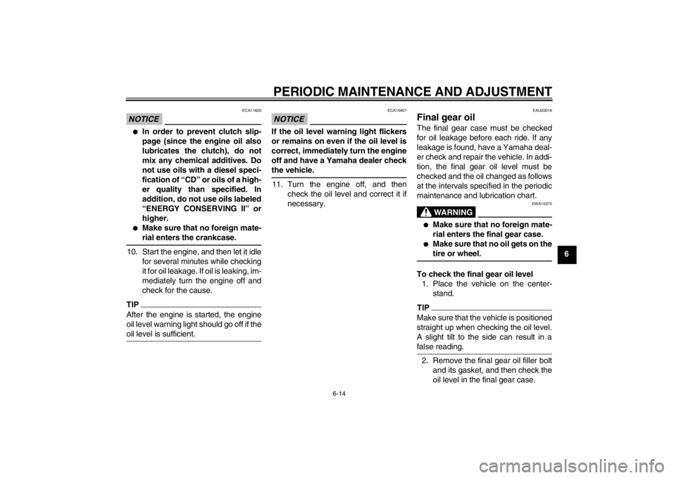
To check the final gear oil level1. Place the vehicle on the center- stand.TIPMake sure that the vehicle is positioned
straight up when checking the oil level.
A slight tilt to the side can result in a
false reading.2. Remove the final gear oil filler boltand its gasket, and then check the
oil level in the final gear case.
U1MCE0E0.book Page 14 Thursday, July 19, 2012 6:59 PM
Page 82 of 118

PERIODIC MAINTENANCE AND ADJUSTMENT
6-15
6
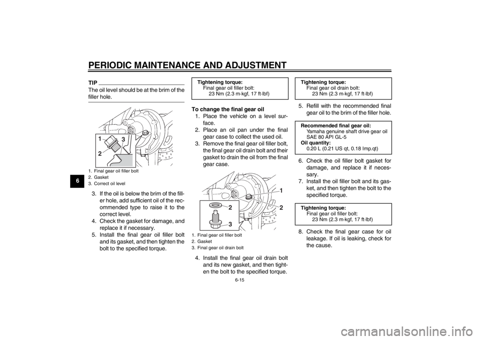
TIPThe oil level should be at the brim of the
filler hole.3. If the oil is below the brim of the fill-er hole, add sufficient oil of the rec-
ommended type to raise it to the
correct level.
4. Check the gasket for damage, and replace it if necessary.
5. Install the final gear oil filler bolt and its gasket, and then tighten the
bolt to the specified torque. To change the final gear oil
1. Place the vehicle on a level sur- face.
2. Place an oil pan under the final gear case to collect the used oil.
3. Remove the final gear oil filler bolt, the final gear oil drain bolt and their
gasket to drain the oil from the final
gear case.
4. Install the final gear oil drain bolt and its new gasket, and then tight-
en the bolt to the specified torque. 5. Refill with the recommended final
gear oil to the brim of the filler hole.
6. Check the oil filler bolt gasket for damage, and replace it if neces-
sary.
7. Install the oil filler bolt and its gas- ket, and then tighten the bolt to the
specified torque.
8. Check the final gear case for oil leakage. If oil is leaking, check for
the cause.1. Final gear oil filler bolt
2. Gasket
3. Correct oil level
3
21
Tightening torque:Final gear oil filler bolt:
23 Nm (2.3 m·kgf, 17 ft·lbf)1. Final gear oil filler bolt
2. Gasket
3. Final gear oil drain bolt
12
3
2
Tightening torque: Final gear oil drain bolt:
23 Nm (2.3 m·kgf, 17 ft·lbf)
Recommended final gear oil: Yamaha genuine shaft drive gear oil
SAE 80 API GL-5
Oil quantity: 0.20 L (0.21 US qt, 0.18 Imp.qt)
Tightening torque: Final gear oil filler bolt:23 Nm (2.3 m·kgf, 17 ft·lbf)
U1MCE0E0.book Page 15 Thursday, July 19, 2012 6:59 PM
Page 92 of 118

PERIODIC MAINTENANCE AND ADJUSTMENT
6-25
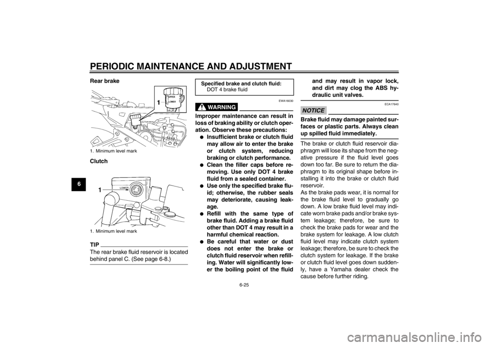
6Rear brake
Clutch
TIPThe rear brake fluid reservoir is located
behind panel C. (See page 6-8.)
WARNING
EWA16030
Improper maintenance can result in
loss of braking ability or clutch oper-
ation. Observe these precautions:●
Insufficient brake or clutch fluid
may allow air to enter the brake
or clutch system, reducing
braking or clutch performance.
●
Clean the filler caps before re-
moving. Use only DOT 4 brake
fluid from a sealed container.
●
Use only the specified brake flu-
id; otherwise, the rubber seals
may deteriorate, causing leak-
age.
●
Refill with the same type of
brake fluid. Adding a brake fluid
other than DOT 4 may result in a
harmful chemical reaction.
●
Be careful that water or dust
does not enter the brake or
clutch fluid reservoir when refill-
ing. Water will significantly low-
er the boiling point of the fluid and may result in vapor lock,
and dirt may clog the ABS hy-
draulic unit valves.
NOTICE
ECA17640
Brake fluid may damage painted sur-
faces or plastic parts. Always clean
up spilled fluid immediately.The brake or clutch fluid reservoir dia-
phragm will lose its shape from the neg-
ative pressure if the fluid level goes
down too far. Be sure to return the dia-
phragm to its original shape before in-
stalling it into the brake or clutch fluid
reservoir.
As the brake pads wear, it is normal for
the brake fluid level to gradually go
down. A low brake fluid level may indi-
cate worn brake pads and/or brake sys-
tem leakage; therefore, be sure to
check the brake pads for wear and the
brake system for leakage. A low clutch
fluid level may indicate clutch system
leakage; therefore, be sure to check the
clutch system for leakage. If the brake
or clutch fluid level goes down sudden-
ly, have a Yamaha dealer check the
cause before further riding.
1. Minimum level mark
1. Minimum level mark
Specified brake and clutch fluid:
DOT 4 brake fluid
U1MCE0E0.book Page 25 Thursday, July 19, 2012 6:59 PM
Page 96 of 118

PERIODIC MAINTENANCE AND ADJUSTMENT
6-29
6
EAU23251
Lubricating the rear suspen-
sion The pivoting points of the rear suspen-
sion must be lubricated by a Yamaha
dealer at the intervals specified in the
periodic maintenance and lubrication
chart.
EAUM1652
Lubricating the swingarm piv-
ots The swingarm pivots must be lubricat-
ed by a Yamaha dealer at the intervals
specified in the periodic maintenance
and lubrication chart.
EAU23272
Checking the front fork The condition and operation of the front
fork must be checked as follows at the
intervals specified in the periodic main-
tenance and lubrication chart.
To check the condition
Check the inner tubes for scratches,
damage and excessive oil leakage.
To check the operation1. Place the vehicle on a level sur- face and hold it in an upright posi-
tion. WARNING! To avoid injury,
securely support the vehicle so
there is no danger of it falling
over.
[EWA10751]
2. While applying the front brake, push down hard on the handlebars
several times to check if the front
fork compresses and rebounds
smoothly.
Recommended lubricant:Lithium-soap-based grease
Recommended lubricant:Lithium-soap-based grease
U1MCE0E0.book Page 29 Thursday, July 19, 2012 6:59 PM
Page 111 of 118

SPECIFICATIONS
8-1
8
Dimensions:Overall length:2230 mm (87.8 in)
Overall width:
750 mm (29.5 in)
Overall height: 1325/1455 mm (52.2/57.3 in)
Seat height: 805/825 mm (31.7/32.5 in)
Wheelbase:
1545 mm (60.8 in)
Ground clearance: 130 mm (5.12 in)
Minimum turning radius: 3100 mm (122.0 in)Weight:Curb weight:289 kg (637 lb)Engine:Engine type:
Liquid cooled 4-stroke, DOHC
Cylinder arrangement: Inline 4-cylinder
Displacement: 1298 cm³
Bore × stroke:
79.0 × 66.2 mm (3.11 × 2.61 in)
Compression ratio: 10.80 : 1
Starting system: Electric starter
Lubrication system:
Wet sump
Engine oil:Recommended brand:YAMALUBE
Type:
SAE 10W-40, 10W-50, 15W-40, 20W-40 or
20W-50
Recommended engine oil grade: API service SG type or higher, JASO
standard MA
Engine oil quantity:
Without oil filter cartridge replacement:3.80 L (4.02 US qt, 3.34 Imp.qt)
With oil filter cartridge replacement:
4.00 L (4.23 US qt, 3.52 Imp.qt)Final gear oil:Type:Yamaha genuine shaft drive gear oil SAE 80 API GL-5
Quantity: 0.20 L (0.21 US qt, 0.18 Imp.qt)
Cooling system:Coolant reservoir capacity (up to the
maximum level mark):0.25 L (0.26 US qt, 0.22 Imp.qt)
Radiator capacity (including all routes): 2.60 L (2.75 US qt, 2.29 Imp.qt)Air filter:Air filter element:Dry elementFuel:Recommended fuel:
Regular unleaded gasoline only
Fuel tank capacity: 25.0 L (6.61 US gal, 5.50 Imp.gal)
Fuel reserve amount: 5.5 L (1.45 US gal, 1.21 Imp.gal)Fuel injection:Throttle body:ID mark:
1MC1 00Spark plug(s):Manufacturer/model: NGK/CPR8EA-9
Spark plug gap:
0.8–0.9 mm (0.031–0.035 in)Clutch:Clutch type:Wet, multiple-discTransmission:Primary reduction ratio:1.563 (75/48)
Final drive: Shaft
–20 –10 0 1020 30 40 50 �C
10 30 50 70 90 110
0 130 �F
SAE 20W-50SAE 20W-40SAE 15W-40SAE 10W-40SAE 10W-50
U1MCE0E0.book Page 1 Thursday, July 19, 2012 6:59 PM
Page 113 of 118

SPECIFICATIONS
8-3
8
Rear suspension:Type:Swingarm (link suspension)
Spring/shock absorber type:
Coil spring/gas-oil damper
Wheel travel: 125.0 mm (4.92 in)Electrical system:Ignition system:
TCI
Charging system: AC magnetoBattery:Model:
GT14B-4
Voltage, capacity: 12 V, 12.0 AhHeadlight:Bulb type:
Halogen bulbBulb voltage, wattage × quantity:Headlight:
12 V, 60.0 W/55.0 W × 2
Tail/brake light:
12 V, 5.0 W/21.0 W × 2
Front turn signal light: LED
Rear turn signal light: 12 V, 21.0 W × 2
Auxiliary light:
LED
License plate light: 12 V, 5.0 W × 1 Meter lighting:
LED
Neutral indicator light: LED
High beam indicator light:
LED
Oil level warning light: LED
Turn signal indicator light: LED
Engine trouble warning light:
LED
ABS warning light: LED
Cruise control “SET” indicator light: LED
Cruise control “ON” indicator light:
LED
Immobilizer system indicator light: LED
Traction control system indicator/warning
light: LED
Fuses:Main fuse 1:
50.0 A
Main fuse 2: 30.0 A
Headlight fuse: 25.0 A
Brake light fuse:
1.0 A
Signaling system fuse: 10.0 A Ignition fuse:
20.0 A
Radiator fan fuse: 10.0 A × 2
Hazard fuse:
7.5 A
Fuel injection system fuse: 15.0 A
ABS control unit fuse: 7.5 A
ABS motor fuse:
30.0 A
ABS solenoid fuse: 20.0 A
Cruise control fuse: 1.0 A
Auxiliary DC jack fuse:
3.0 A
Backup fuse: 7.5 A
Windshield motor fuse: 20.0 A
Electronic throttle valve fuse:
7.5 A
U1MCE0E0.book Page 3 Thursday, July 19, 2012 6:59 PM
Page 115 of 118

INDEX
AABS ...................................................... 3-26
ABS warning light ................................... 3-5
Accessory box ...................................... 3-36
Air filter element, cleaning .................... 6-17
Auxiliary DC jack .................................. 3-45
Auxiliary light ........................................ 6-36BBattery .................................................. 6-31
Brake and clutch fluid levels, checking ............................................. 6-24
Brake and clutch fluids, changing ......... 6-26
Brake and clutch levers, checking and lubricating ........................................... 6-27
Brake and shift pedals, checking and
lubricating ........................................... 6-27
Brake lever ........................................... 3-26
Brake lever free play, checking ............ 6-23
Brake light switches .............................. 6-23
Brake pedal .......................................... 3-26CCables, checking and lubricating .......... 6-26
Care ........................................................ 7-1
Catalytic converters .............................. 3-31
Centerstand and sidestand, checking and lubricating .................................... 6-28
Clutch lever.................................. 3-25, 6-22
Coolant ................................................. 6-16
Cowling vents, opening and closing ..... 3-37
Cruise control indicator lights ................. 3-4
Cruise control switches ......................... 3-24
Cruise control system ............................. 3-6DDimmer/Pass switch ............................. 3-23 D-mode (drive mode) ............................ 3-22
EEngine break-in .......................................5-3
Engine idling speed, checking............... 6-18
Engine oil and oil filter cartridge ............ 6-12
Engine trouble warning light .................... 3-4FFinal gear oil.......................................... 6-14
Front and rear brake pads, checking .... 6-24
Front fork, adjusting .............................. 3-39
Front fork, checking...............................6-29
Front turn signal light............................. 6-34
Fuel ....................................................... 3-30
Fuel consumption, tips for reducing ........ 5-3
Fuel tank breather/overflow hose .......... 3-31
Fuel tank cap......................................... 3-29
Fuses, replacing .................................... 6-32HHandlebar position, adjusting ................ 3-37
Handlebar switches ............................... 3-23
Hazard switch........................................ 3-24
Headlight beams, adjusting ................... 3-37
Headlight bulb ....................................... 6-34
High beam indicator light......................... 3-4
Horn switch ........................................... 3-24IIdentification numbers ............................. 9-1
Ignition circuit cut-off system ................. 3-43
Immobilizer system .................................3-1
Immobilizer system indicator light ........... 3-6
Indicator lights and warning lights ........... 3-4LLicense plate light bulb, replacing ......... 6-35
MMain switch/steering lock ........................ 3-2
Maintenance and lubrication, periodic .... 6-4
Maintenance, emission control system ... 6-3
Matte color, caution ................................ 7-1
Menu switch .......................................... 3-24
Model label ............................................. 9-1
Multi-function meter unit ......................... 3-9NNeutral indicator light .............................. 3-4OOil level warning light .............................. 3-4PPanels, removing and installing .............. 6-8
Parking.................................................... 5-4
Part locations .......................................... 2-1RRear suspension, lubricating ................ 6-29
Rear view mirrors.................................. 3-39
Rider seat height, adjusting .................. 3-33SSafety information ................................... 1-1
Seats..................................................... 3-32
Select switch ......................................... 3-24
Shifting .................................................... 5-2
Shift pedal ............................................. 3-25
Shock absorber assembly, adjusting .... 3-41
Sidestand .............................................. 3-42
Spark plugs, checking........................... 6-11
Specifications.......................................... 8-1
Start/Engine stop switch ....................... 3-24
Starting the engine.................................. 5-1
Steering, checking ................................ 6-30
Storage ................................................... 7-4
U1MCE0E0.book Page 1 Thursday, July 19, 2012 6:59 PM