2013 VOLVO V60 brake
[x] Cancel search: brakePage 305 of 422

07 During your journey
Driving with a trailer
07
* Option/accessory, for more information, see Introduction.303
G018929
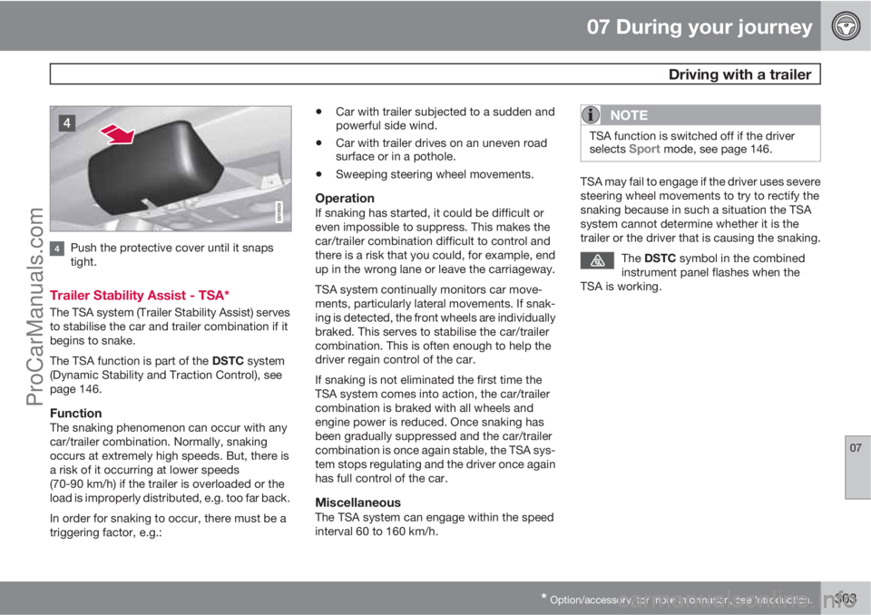
Push the protective cover until it snaps
tight.
Trailer Stability Assist - TSA*
The TSA system (Trailer Stability Assist) serves
to stabilise the car and trailer combination if it
begins to snake.
The TSA function is part of the DSTC system
(Dynamic Stability and Traction Control), see
page 146.
FunctionThe snaking phenomenon can occur with any
car/trailer combination. Normally, snaking
occurs at extremely high speeds. But, there is
a risk of it occurring at lower speeds
(70-90 km/h) if the trailer is overloaded or the
load is improperly distributed, e.g. too far back.
In order for snaking to occur, there must be a
triggering factor, e.g.:
•Car with trailer subjected to a sudden and
powerful side wind.
•Car with trailer drives on an uneven road
surface or in a pothole.
•Sweeping steering wheel movements.
OperationIf snaking has started, it could be difficult or
even impossible to suppress. This makes the
car/trailer combination difficult to control and
there is a risk that you could, for example, end
up in the wrong lane or leave the carriageway.
TSA system continually monitors car move-
ments, particularly lateral movements. If snak-
ing is detected, the front wheels are individually
braked. This serves to stabilise the car/trailer
combination. This is often enough to help the
driver regain control of the car.
If snaking is not eliminated the first time the
TSA system comes into action, the car/trailer
combination is braked with all wheels and
engine power is reduced. Once snaking has
been gradually suppressed and the car/trailer
combination is once again stable, the TSA sys-
tem stops regulating and the driver once again
has full control of the car.
MiscellaneousThe TSA system can engage within the speed
interval 60 to 160 km/h.
NOTE
TSA function is switched off if the driver
selects Sport mode, see page 146.
TSA may fail to engage if the driver uses severe
steering wheel movements to try to rectify the
snaking because in such a situation the TSA
system cannot determine whether it is the
trailer or the driver that is causing the snaking.
The DSTC symbol in the combined
instrument panel flashes when the
TSA is working.
ProCarManuals.com
Page 306 of 422

07 During your journey
Towing and recovery
07
304
Towing
Find out the statutory maximum speed limit for
towing before towing begins.
1. Unlock the steering lock by inserting the
remote control key in the ignition switch
and giving a long press on the START/
STOP ENGINE button - key position II is
activated, see page 78 for more informa-
tion on key positions.
2. The remote control key must remain in the
ignition switch while the car is being towed.
3. Keep the towline taut when the towing
vehicle reduces speed by holding your foot
gently pressed on the brake pedal -
thereby avoiding unnecessary jerking.
4. Be prepared to brake to stop.
WARNING
•Check that the steering lock is unlocked
before towing.
•The remote control key must be in key
position II - in position I all airbags are
deactivated.
•Never remove the remote control key
from the ignition switch when the car is
being towed.
WARNING
The brake servo and power steering do not
work when the engine is switched off - the
brake pedal needs to be depressed
about 5 times more heavily and the steering
is considerably heavier than normal.
Manual gearboxPrior to towing:
–Move gear lever into neutral and release
the parking brake.
Automatic gearbox Geartronic
IMPORTANT
Note that the car must always be towed with
the wheels rolling forward.
•Cars with automatic gearbox must not
be towed at speeds above 80 km/h or
further than 80 km.
Prior to towing:
–
Move the gear selector to position N and
release the parking brake.
Automatic gearbox PowershiftThe model with Powershift transmission
should not be towed as it is dependent on the
engine running in order to receive sufficientlubrication. If towing still has to take place, the
route must be as short as possible and then
with very low speed.
In the event of uncertainty as to whether or not
the car is equipped with Powershift transmis-
sion, this can be verified by checking the des-
ignation on the transmission's label under the
bonnet - see page 370. The designa-
tion ”MPS6” means that it is Powershift – trans-
mission otherwise it is Geartronic automatic
transmission.
IMPORTANT
Avoid towing.
•However, the car can be towed for a
short distance at low speed to move it
from a dangerous position - not further
than 10 km and not faster than
10 km/h. Note that the car must always
be towed with the wheels rolling for-
ward.
•In the event of moving a longer distance
than 10 km, the car must be transported
with the drive wheels raised from the
road - professional recovery is recom-
mended.
Prior to towing:
–
Move the gear selector to position N and
release the parking brake.
ProCarManuals.com
Page 317 of 422

08 Wheels and tyres
Changing wheels
08
* Option/accessory, for more information, see Introduction.315 Removing
Set up the warning triangle, see page 318 if a
wheel must be replaced at a busy location. The
car and jack* must be on a firm horizontal sur-
face.
1. Apply the parking brake and engage
reverse gear, or position P if the car has an
automatic gearbox.
WARNING
Check that the jack is not damaged, that the
threads are thoroughly lubricated and that it
is free from dirt.
NOTE
Volvo recommends only using the jack* that
belongs to the car model in question, which
is indicated on the jack's label.
The label also indicates the jack's maximum
lift capacity at a specified minimum lifting
height.
2. Take out the jack*, wheel wrench* and
removal tool for wheel covers* located
under the cargo floor in the cargo area. If
another jack is selected, see page 328.
3. Place chocks in front of and behind the
wheels which will remain on the ground.Use heavy wooden blocks or large stones
for example.
4. Cars with steel rims have removable wheel
covers. Use the removal tool to hook in and
pull off any full-wheel wheel covers. Alter-
natively, the wheel covers can be pulled
away by hand.
5. Screw together the towing eye with the
wheel wrench* until the stop position as
illustrated below.
IMPORTANT
The towing eye must be screwed into all
threads in the wheel bolt wrench.
6. Loosen the wheel bolts ½-1 turn anticlock-
wise with the wheel wrench.
WARNING
Never position anything between the
ground and the jack, nor between the jack
and the car's jacking point.
7. There are two jacking points on each side
of the car. There is a recess in the plastic
cover at each point. Crank the foot of the
ProCarManuals.com
Page 331 of 422

09 Maintenance and service
Engine compartment09
329
Turn the handle about 20-25 degrees
clockwise. You will hear when the catch
releases.
Move the catch to the left and open the
bonnet. (The catch hook is located
between the headlamp and grille, see illus-
tration.)
WARNING
Check that the bonnet locks properly when
closed.
Engine compartment, overview
The appearance of the engine compartment may
vary depending on engine variant.
Coolant expansion tank
Power steering fluid reservoir
Engine oil dipstick1
Radiator
Filling engine oil
Reservoir for brake and clutch fluid
(located on the driver's side)
Battery
Relay and fuse box
Filling washer fluid
Air filter
WARNING
The ignition system has very high voltage
and output. The voltage in the ignition sys-
tem is highly dangerous. The remote control
key must always be in 0 position when work
is being done in the engine compartment,
see page 78.
Do not touch the spark plugs or ignition coil
when the remote control key is in II position
or when the engine is hot.
Checking the engine oil
1Engines with electronic oil level sensor have no dipstick (5-cyl. diesel).
ProCarManuals.com
Page 335 of 422

09 Maintenance and service
Engine compartment09
333
For capacities and for standards regarding
water quality, see page 381.
Check the coolant regularlyThe level must lie between the MIN and MAX
marks on the expansion tank. If the system is
not filled sufficiently, high temperatures could
occur, causing a risk of damage to the engine.
IMPORTANT
•A high content of chlorine, chlorides
and other salts may cause corrosion in
the cooling system.
•Always use coolant with anti-corrosion
agent as recommended by Volvo.
•Ensure that the coolant mixture is 50%
water and 50% coolant.
•Mix the coolant with approved quality
tap water. In the event of any doubt
about water quality, used ready-mixed
coolant in accordance with Volvo rec-
ommendations.
•When changing coolant/replacing cool-
ing system components, flush the cool-
ing system clean with approved quality
tap water or flush with ready-mixed
coolant.
•The engine must only be run with a well-
filled cooling system. Otherwise, tem-
peratures that are too high may occur
resulting in the risk of damage (cracks)
in the cylinder head.
Brake and clutch fluid
Checking the levelBrake and clutch fluid have a common reser-
voir. The level must be between the MIN and
MAX marks that are visible inside the reservoir.
Check the level regularly.
Change the brake fluid every other year or at
every other regular service.
For capacities and recommended fluid grade,
see page 381. The fluid should be changed
annually on cars driven in conditions requiring
hard, frequent braking, such as driving in
mountains or tropical climates with high
humidity.
WARNING
If the brake fluid is under the MIN level in the
brake fluid reservoir, do not drive further
before topping up the brake fluid. Volvo rec-
ommends that the reason for the loss of
brake fluid is investigated by an authorised
Volvo workshop.
ProCarManuals.com
Page 336 of 422

09 Maintenance and service
Engine compartment 09
334
Filling
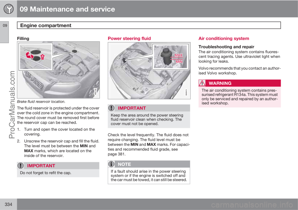
Brake fluid reservoir location.
The fluid reservoir is protected under the cover
over the cold zone in the engine compartment.
The round cover must be removed first before
the reservoir cap can be reached.
1. Turn and open the cover located on the
covering.
2. Unscrew the reservoir cap and fill the fluid.
The level must be between the MIN and
MAX marks, which are located on the
inside of the reservoir.
IMPORTANT
Do not forget to refit the cap.
Power steering fluid
IMPORTANT
Keep the area around the power steering
fluid reservoir clean when checking. The
cover must not be opened.
Check the level frequently. The fluid does not
require changing. The fluid level must be
between the MIN and MAX marks. For capaci-
ties and recommended fluid grade, see
page 381.
NOTE
If a fault should arise in the power steering
system or if the engine is switched off and
the car must be towed, it can still be steered.
Air conditioning system
Troubleshooting and repairThe air conditioning system contains fluores-
cent tracing agents. Use ultraviolet light when
looking for leaks.
Volvo recommends that you contact an author-
ised Volvo workshop.
WARNING
The air conditioning system contains pres-
surised refrigerant R134a. This system must
only be serviced and repaired by an author-
ised workshop.
ProCarManuals.com
Page 337 of 422

09 Maintenance and service
Lamps09
335 General
All bulbs are specified, see page 339. The fol-
lowing list contains locations of bulbs and
other light sources that are specialised or
unsuitable for changing except at a workshop:
•Active Xenon headlamps - ABL (Xenon
lamps)
•Direction indicators, door mirrors
•Approach lighting, door mirrors
•Courtesy lighting
•Glovebox lighting
•General interior lighting in the roof
•Reading lamps
•Side position, position lamps rear
•Brake light
•LED lights, general
WARNING
On cars with Xenon headlamps, the
replacement of Xenon lamps must be car-
ried out at a workshop - an authorised Volvo
workshop is recommended. Working with
Xenon lamps demands extreme caution
because the headlamp is equipped with a
high voltage unit.
WARNING
The car’s electrical system must be in key
position 0 when replacing bulbs, see
page 78
IMPORTANT
Never touch the glass part of the bulbs with
your fingers. Grease and oils from your fin-
gers are vaporised by the heat, coating the
reflector and then causing damage.
Headlamps frontAll of the headlamp bulbs are replaced via the
engine compartment. Loosen and remove the
whole headlamp.
Removing the headlamp1. Set the car's electrical system in key posi-
tion 0, see page 78:
2. (First illustration)
Pull out the headlamp's locking pins.
Release the headlamp by alternately
tilting and pulling it out.
IMPORTANT
Do not pull the electrical cable, only the con-
nector.
ProCarManuals.com
Page 340 of 422

09 Maintenance and service
Lamps 09
338
Lamp housing, rear
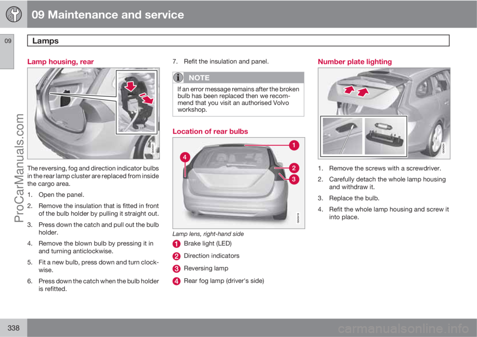
The reversing, fog and direction indicator bulbs
in the rear lamp cluster are replaced from inside
the cargo area.
1. Open the panel.
2. Remove the insulation that is fitted in front
of the bulb holder by pulling it straight out.
3. Press down the catch and pull out the bulb
holder.
4. Remove the blown bulb by pressing it in
and turning anticlockwise.
5. Fit a new bulb, press down and turn clock-
wise.
6. Press down the catch when the bulb holder
is refitted.7. Refit the insulation and panel.
NOTE
If an error message remains after the broken
bulb has been replaced then we recom-
mend that you visit an authorised Volvo
workshop.
Location of rear bulbs
Lamp lens, right-hand side
Brake light (LED)
Direction indicators
Reversing lamp
Rear fog lamp (driver's side)
Number plate lighting
1. Remove the screws with a screwdriver.
2. Carefully detach the whole lamp housing
and withdraw it.
3. Replace the bulb.
4. Refit the whole lamp housing and screw it
into place.
ProCarManuals.com