2013 VOLKSWAGEN TRANSPORTER engine
[x] Cancel search: enginePage 428 of 486
A WARNING (Continued)
• Always follow the instructions In the checklist and observe the general safety pro-
Sealing and inflating tyres
r-"'('n First read and observe the Introductory L-J,.:.U Information and safety warnings & on page 425.
Sealing a tyre
• Unscrew the cap from the tyre valve.
• Use the valve core extractor 302 CD to screw the valve core out of the tyre valve. Place the core on a clean surface.
• Shake the tyre filler bottle 302 ® vigo-rously up and down several times.
• Screw the filler hose 302 @tightly onto the tyre filler bottle in a clockwise direction. The plastic foil on the plug is pierced automatically.
• Remove the plug from the filler hose 302@ and place the open end fully on the tyre valve.
• Hold the bottle upside down and inject the en-tire contents of the tyre filler bottle into the tyre.
• Remove the empty tyre filler bottle from the valve.
• Use the valve core extractor 302 CD to screw the valve core back onto the tyre valve.
Inflating the tyre
• Screw the tyre filler hose 302 ® of the air compressor tightly onto the tyre valve.
• Check that the bleed screw 302 (?) is closed.
• Start the engine and let it run.
• Insert the plug 302 ®into one of the ve-hicle's 12-volt sockets 163.
• Use the on/off switch 302 ®to switch on the air compressor.
• Run the compressor until the tyre pressure has reached 2.0-2.5 bar (29-36 psi I 200-250 kPa) maximum running time is 6 minutes
• Switch off the air compressor.
• If a pressure level of 2.0-2.5 bar (29-36 psi I 200 -250 kPa) cannot be achieved unscrew the tyre filler hose from the tyre valve.
428 I If and when
• Drive (or reverse) the vehicle approximately 1 0 metres so that the sealing compound is more evenly distributed in the tyre.
• Screw the tyre filler hose for the air compressor firmly back onto the tyre valve and inflate the tyre again.
• If the required pressure still cannot be reached, the tyre is too badly damaged. The tyre cannot be sealed with the breakdown set. Do not drive on. Seek expert assistance &.
• Disconnect the air compressor and unscrew the tyre filler hose from the tyre valve.
• Drive the vehicle no faster than 80 km/h (50 mph) once a tyre pressure of 2.0-2.5 bar (29-36 psi I 200-250 kPa) has been reached.
• Check the tyre pressure after driving for 10 mi-nutes 429.
A WARNING
The tyre filler hose and the air compressor can get hot during Inflation.
• Protect your hands and skin from the hot components.
• Do not place the hot tyre filler hose or the hot air compressor on any Inflammable mate-rials.
• Allow the device to cool down fully before stowing.
• If the tyre will not Inflate to at least 2.0 bar (29 psi/ 200 kPa), the tyre Is too damaged. The sealant Is unable to seal the tyre. Do not drive on. Seek expert assistance.
CD
Switch the air compressor off after a maximum of 6 minutes to avoid overheating. Let the air compressor cool down for a few minutes be-fore switching it back on.
Page 429 of 486
Test after driving for 10 minutes
r-'('n First read and observe the Introductory L-J,:.LI Information and safety warnings & on page 425.
Reconnect the tyre filler hose =>Fig. 302 ®and check the tyre pressure on the Tyre Pressure Loss Indicator®.
1.3 bar (19 psi /130 kPa) and lower:
• Do not drive on I The tyre cannot be sealed adequately with the breakdown set.
• Seek expert assistance => &.
1.4 bar (20 psi /140 kPa) and higher:
• Set the tyre pressure back to the correct value =>page 367.
• Resume your journey to the nearest qualified workshop. Do not exceed a maximum speed of 80 km/h (50 mph).
• The damaged tyre should be replaced at the qualified workshop.
Fuses
i:llJ Introduction
This chapter contains information on the following subjects:
Fuse box in the dash panel . . . . . . . . . . . . . . . 430
Fuses in the engine compartment . . . . . . . . . . 431 Changing a blown fuse ................... 431
At the time of print we are unable to provide an up-to-date overview of the locations of the fuses for the electrical consumers. This is because the vehi-cle is under constant development, because fuses are assigned differently depending on the vehicle equipment level and because several consumers may use a single fuse. You can get more informa-tion about the fuse layout from a Volkswagen Com-mercial Vehicles dealership.
Several electrical consumers could share a single fuse. Conversely, a single consumer could have more than one fuse.
Therefore fuses should only be replaced when the cause of the fault has been rectified. If a new fuse blows shortly after insertion, have the electrical system checked by a qualified workshop as soon as possible.
A WARNING
Driving with an unsealed tyre is dangerous as it can cause accidents and serious Injuries.
• Do not carry on driving if the tyre pressure Is 1.3 bar (19 psi /130 kPa) or lower.
• Seek expert assistance.
• Drink holder =>page 153
• Preparation for working in the engine compart-ment =>page 350
• Battery =>page 362
A WARNING
High voltages in the electrical system can cause electric shocks, serious burns and death.
• Never touch the electrical wiring of the ig-nition system.
• Avoid causing short circuits in the electri-cal system.
A WARNING
Using unsuitable or repaired fuses and bridg-ing an electrical circuit without fuses can cause a fire and serious injuries.
Practical tips I 429
Page 431 of 486
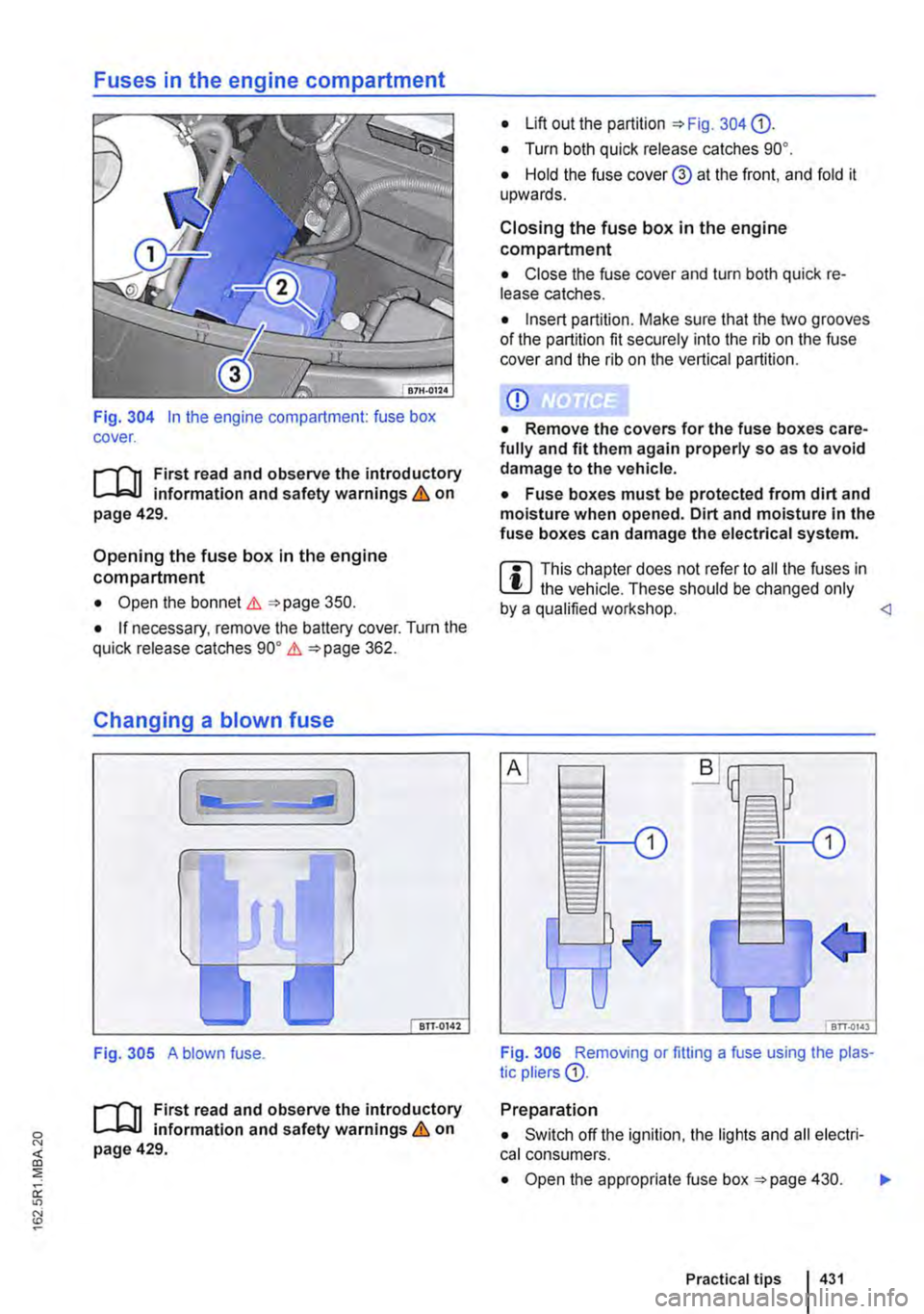
Fig. 304 In the engine compartment: fuse box cover.
;-('n First read and observe the introductory L-Jc.IJ information and safety warnings & on page 429.
Opening the fuse box in the engine compartment
• Open the bonnet .1. =<>page 350.
• If necessary, remove the battery cover. Turn the quick release catches go• .1. =<>page 362.
Changing a blown fuse
Fig. 305 A blown fuse.
;-('n First read and observe the introductory L-Jc.IJ information and safety warnings & on page 429.
• Lift out the partition =<>Fig. 304 0).
• Turn both quick release catches go•.
• Hold the fuse cover@ at the front. and fold it upwards.
Closing the fuse box in the engine compartment
• Close the fuse cover and turn both quick re-lease catches.
• Insert partition. Make sure that the two grooves of the partition fit securely into the rib on the fuse cover and the rib on the vertical partition.
CD
• Remove the covers for the fuse boxes care-fully and fit them again properly so as to avoid damage to the vehicle.
• Fuse boxes must be protected from dirt and moisture when opened. Dirt and moisture in the fuse boxes can damage the electrical system.
m This chapter does not refer to all the fuses in L!J the vehicle. These should be changed only by a qualified workshop.
Preparation
• Switch off the ignition, the lights and all electri-cal consumers.
• Open the appropriate fuse box =<>page 430. .,..
Practical tips I 431
Page 432 of 486
Detecting a blown fuse
If the metal strip is melted this indicates that the fuse has blown 305.
Shine a torch onto the fuse. This will help you to spot the blown fuse more easily.
Changing a fuse
• If applicable, take the plastic pliers 306 G) out of the fuse box cover.
• For small fuses. push the catch on G) from above 306
• For larger fuses, push the catch G) onto the fuse from the side 306@
Changing bulbs
o::n Introduction
This chapter contains information on the following subjects:
Indicator lamp . . . . . . . . . . . . . . . . . . . . . . . . . 433
Information on changing bulbs . 433 LED lights on the vehicle . . . . . . . . . 434
Changing bulbs in H4 halogen headlights 435
Changing bulbs in H7 halogen headlights . . . 437
Changing bulbs in the LED headlights . . . 438
Changing the bulbs in the fog light . . . . . . . . . 439 Changing the bulbs in the tail light cluster on vehicles with tailgate . . . . . . . . . . . . . . . . . . . . . 440
Changing the bulbs in the tail light cluster on vehicles with wing doors .................. 441
Changing the bulbs in the LED tail light cluster . . . . . . . . . . . . . . . . . . . . . . . . . 442 Changing the side turn signal bulbs . . . . . . . . 443
Changing the vehicle bulbs requires considerable technical skill. Therefore if you do not feel confi-dent with the procedure. Volkswagen Commercial Vehicles recommends having the bulbs changed by a Volkswagen Commercial Vehicles dealership or other professional assistance. You must contact a qualified workshop if other vehicle parts around the lights need to be removed or LED lights need to be replaced.
You should keep a box with spare light bulbs for the lights that ensure the vehicle is roadworthy in the vehicle at all times. Spare bulbs are available from Volkswagen Commercial Vehicles dealers. In some countries it is a legal requirement to have these spare bulbs in the vehicle.
lt may be illegal to drive with a defective bulb in the exterior lighting.
4321 If and when
• Pull out the blown fuse.
• If the fuse has blown, replace it with a new fuse of the same amp rating (same colour and same markings) and same size
• Replace the cover.
CD
You can damage another position In the electri-cal system by using a fuse with a higher amp rating.
You can change the following bulbs yourself:
• Bulbs of the halogen headlights.
• Turn signal bulb in the LED headlights.
• Bulbs in non-LED tail light cluster.
• Turn signal and reversing light bulb in the LED tail light cluster.
• Bulb of turn signal repeater.
• Bulb of fog lights.
All LED lights in the vehicle should always be changed by an expert.
Additional bulb specifications
Some bulbs in headlights or In tail light clusters might have factory specifications that are different to standard bulbs. The designation is inscribed on the bulb, either on the glass part or on the base.
Additional information and warnings:
• Exterior views 5
• Lights and vision 106
• Preparation for working In the engine compart-ment 350
• Vehicle toolkit 416
• Fuses 429
A WARNING
Accidents can occur If roads are not suffi-ciently Illuminated and other road users have difficulty seeing the vehicle, or cannot see it atall. 11>
Page 433 of 486
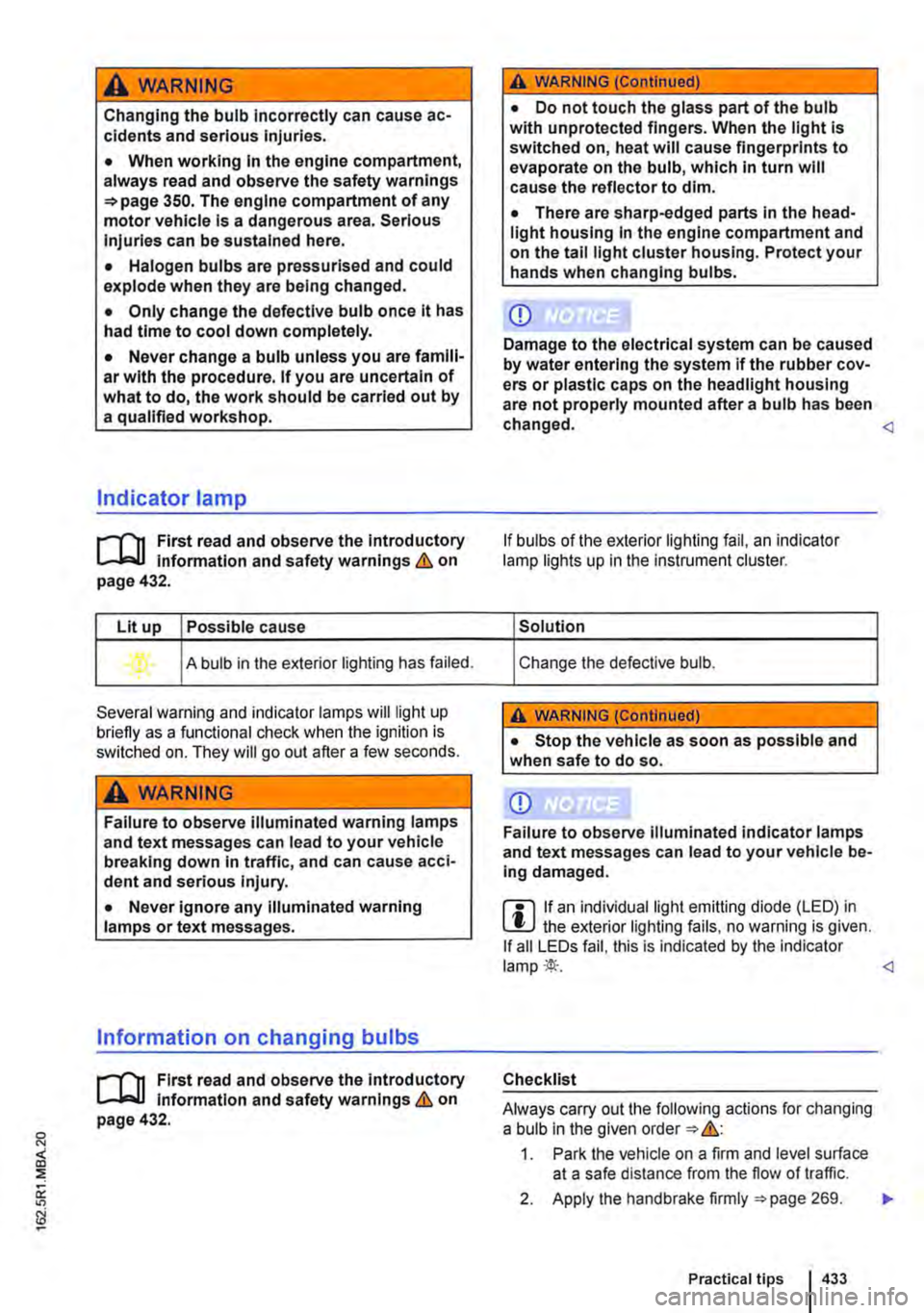
A WARNING
Changing the bulb incorrectly can cause ac-cidents and serious Injuries.
• When working In the engine compartment, always read and observe the safety warnings =>page 350. The engine compartment of any motor vehicle Is a dangerous area. Serious Injuries can be sustained here.
• Halogen bulbs are pressurised and could explode when they are being changed.
• Only change the defective bulb once it has had time to cool down completely.
• Never change a bulb unless you are famili-ar with the procedure. If you are uncertain of what to do, the work should be carried out by a qualified workshop.
Indicator lamp
r--f"n First read and observe the introductory L-.J,:.lJ Information and safety warnings & on page 432.
Lit up Possible cause
A bulb in the exterior lighting has failed.
Several warning and indicator lamps will light up briefly as a functional check when the ignition is switched on. They will go out after a few seconds.
A WARNING
Failure to observe illuminated warning lamps and text messages can lead to your vehicle breaking down In traffic, and can cause acci-dent and serious Injury.
• Never ignore any illuminated warning lamps or text messages.
Information on changing bulbs
r--f"n First read and observe the introductory L-.J,:.lJ Information and safety warnings & on page 432.
A WARNING (Continued)
• Do not touch the glass part of the bulb with unprotected fingers. When the light is switched on, heat will cause fingerprints to evaporate on the bulb, which In turn will cause the reflector to dim.
• There are sharp-edged parts In the head-light housing In the engine compartment and on the tall light cluster housing. Protect your hands when changing bulbs.
CD
Damage to the electrical system can be caused by water entering the system if the rubber cov-ers or plastic caps on the headlight housing are not properly mounted after a bulb has been changed.
If bulbs of the exterior lighting fail, an indicator lamp lights up in the instrument cluster.
Solution
Change the defective bulb.
A WARNING (Continued)
• Stop the vehicle as soon as possible and when safe to do so.
CD
Failure to observe Illuminated indicator lamps and text messages can lead to your vehicle be-ing damaged.
m if an individual light emitting diode (LED) in W the exterior lighting fails, no warning is given. If all LEDs fail, this is indicated by the indicator lamp*··
Checklist
Always carry out the following actions for changing a bulb in the given order => &:
1. Park the vehicle on a firm and level surface at a safe distance from the flow of traffic.
2. Apply the handbrake firmly =>page 269. .,..
Practical tips I 433
Page 434 of 486
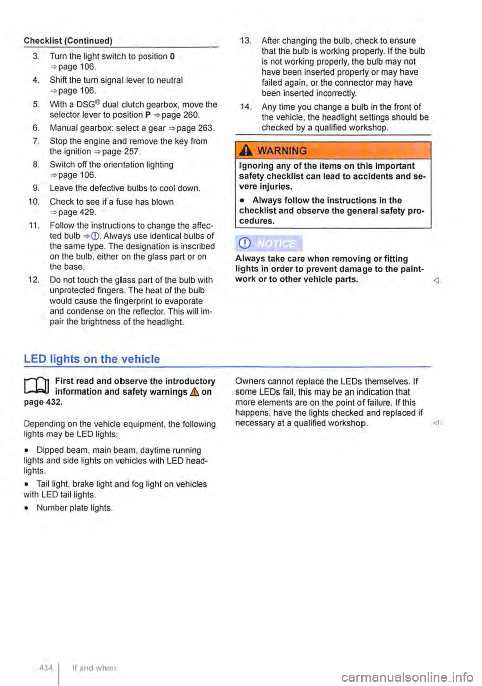
Checklist (Continued)
3. Turn the light switch to position o 106.
4. Shift the tu m signal lever to neutral 106.
5. With a DSG® dual clutch gearbox, move the selector lever to position P 260.
6. Manual gearbox: select a gear 263.
7. Stop the engine and remove the key from the ignition 257.
8. Switch off the orientation lighting 106.
9. Leave the defective bulbs to cool down.
10. Check to see if a fuse has blown 429.
11. Follow the instructions to change the affec-ted bulb Always use identical bulbs of the same type. The designation is inscribed on the bulb, either on the glass part or on the base.
12. Do not touch the glass part of the bulb with unprotected fingers. The heat of the bulb would cause the fingerprint to evaporate and condense on the renector. This will im-pair the brightness of the headlight.
LED lights on the vehicle
r--f'n First read and observe the introductory L-I=J.I information and safety warnings & on page 432.
Depending on the vehicle equipment, the following lights may be LED lights:
• Dipped beam, main beam, daytime running lights and side lights on vehicles with LED head-lights.
• Tail light, brake light and fog light on vehicles with LED tail lights.
• Number plate lights.
434 If and when
13. After changing the bulb, check to ensure that the bulb is working properly. If the bulb is not working properly, the bulb may not have been inserted properly or may have failed again, or the connector may have been inserted incorrectly.
14. Any time you change a bulb in the front of the vehicle, the headlight settings should be checked by a qualified workshop.
A WARNING
Ignoring any of the items on this important safety checklist can lead to accidents and se-vere Injuries.
• Always follow the instructions in the checklist and observe the general safety pro-cedures.
CD
Always take care when removing or fitting lights in order to prevent damage to the paint-work or to other vehicle parts. <1
Owners cannot replace the LEDs themselves. If some LEDs fail, this may be an indication that more elements are on the point of failure. If this happens, have the lights checked and replaced if necessary at a qualified workshop.
Page 443 of 486
Changing the side turn signal bulbs
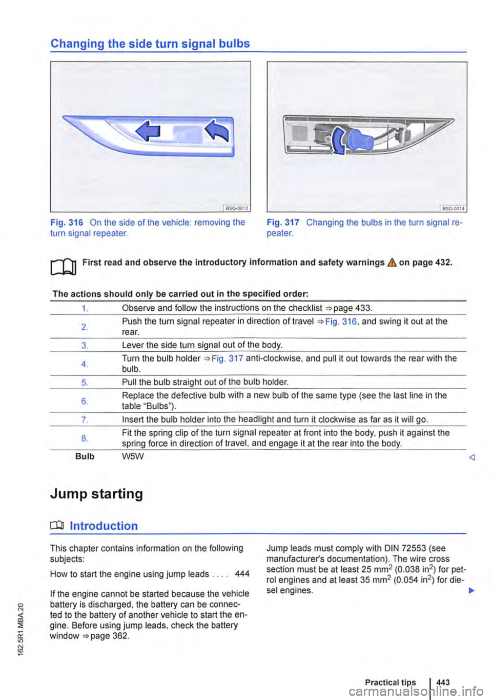
BSG-0013
Fig. 316 On the side of the vehicle: removing the turn signal repeater. Fig. 317 Changing the bulbs in the turn signal re-peater.
ro First read and observe the introductory Information and safety warnings & on page 432.
The actions should only be carried out in the specified order:
1. Observe and follow the instructions on the checklist 433.
2.
3.
4.
5.
6.
7.
8.
Bulb
Push the turn signal repeater in direction of travel 316, and swing it out at the rear.
Lever the side turn signal out of the body.
Turn the bulb holder 317 anti-clockwise, and pull it out towards the rear with the bulb.
Pull the bulb straight out of the bulb holder.
Replace the defective bulb with a new bulb of the same type (see the last line in the table "Bulbs").
Insert the bulb holder into the headlight and turn it clockwise as far as it will go.
Fit the spring clip of the turn signal repeater at front into the body, push it against the spring force in direction of travel, and engage it at the rear into the body.
W5W
Jump starting
CQJ Introduction
This chapter contains information on the following subjects:
How to start the engine using jump leads . . . . 444
Jump leads must comply with DIN 72553 (see manufacturer's documentation). The wire cross section must be at least 25 mm2 (0.038 in2) for pet-rol engines and at least 35 mm2 (0.054 in2) for die-
sel engines. ,..
Practical tips 443
Page 444 of 486
Additional information and warnings:
• Pull-away assist systems 282
• Preparation for working in the engine compart-ment 350
• Battery 362
A WARNING
Using the jump leads Incorrectly or complet-ing the jump start procedure incorrectly can cause the battery to explode, which can lead to severe Injuries. Please note the following In order to reduce the risk of the battery ex-ploding:
• All work on the vehicle battery and the electrical system can cause serious chemical burns, fire or electric shocks. Always read the warnings and safety Information before carrying out any kind of work on the vehicle battery 362, Vehicle battery.
• The vehicle battery providing assistance must have approximately the same voltage as the flat vehicle battery (12-volts) and approxi-mately the same capacity (see Imprint on bat-tery).
• Never charge a vehicle battery once it has been frozen. Discharged vehicle batteries can even freeze at temperatures of around o•c (+32"F).
• The battery should be replaced if it is or has ever been frozen.
A WARNING (Continued)
• A highly explosive mixture of gases Is giv-en off when the vehicle battery Is jump star-ted. Always keep fire, sparks, naked flames and lit cigarettes away from the vehicle bat-tery. Never use a mobile telephone when the jump leads are being connected or discon-nected.
• Only charge the battery in a well-ventila-ted space as the battery emits a highly explo-sive mixture of gases when the vehicle Is be-Ing jump started.
• Position the jump leads so that they never come Into contact with any moving parts In the engine compartment.
• Never confuse the negative and positive terminals or connect the jump leads Incor-rectly.
• Observe the jump lead manufacturer's In-structions.
CD
Please note the following In order to avoid con-siderable damage to the vehicle electrical sys-tem:
• A short circuit can be caused If the jump leads are wrongly connected.
• The vehicles must not touch each other, as any contact could mean that electricity could flow as soon as the positive terminals are con-nected.
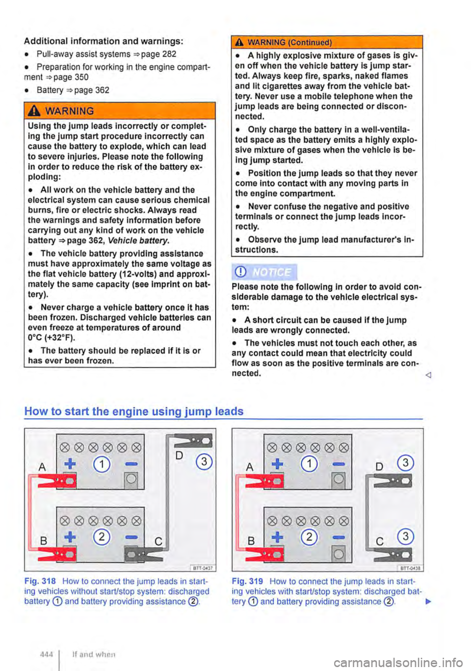
00®00® :liOIIr 11
D
A + CD -®
fOl
0®®®®®
B + 0 -c 11'"1111
! 8TT.QA37
Fig. 318 How to connect the jump leads in start-ing vehicles without start/stop system: discharged battery
B c
Fig. 319 How to connect the jump leads in start-ing vehicles with start/stop system: discharged bat-tery