2013 VOLKSWAGEN TRANSPORTER engine
[x] Cancel search: enginePage 412 of 486
Making you and your vehicle safe
8S0.00)7
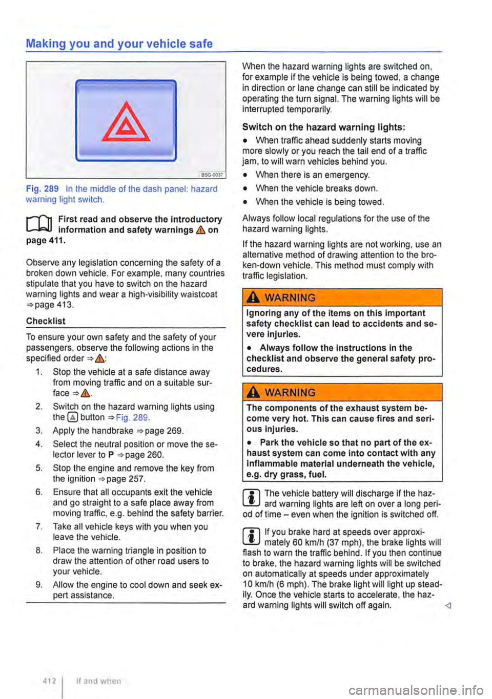
Fig. 289 In the middle of the dash panel: hazard warning light switch.
f"'""'('n First read and observe the Introductory L-lo:.U Information and safety warnings Lb. on page 411.
Observe any legislation concerning the safety of a broken down vehicle. For example, many countries stipulate that you have to switch on the hazard warning lights and wear a high-visibility waistcoat =>page 413.
Checklist
To ensure your own safety and the safety of your passengers, observe the following actions in the specified order => &:
1. Stop the vehicle at a safe distance away from moving traffic and on a suitable sur-face=>&.
2. Switch on the hazard warning lights using button =>Fig. 289.
3. Apply the handbrake =>page 269.
4. Select the neutral position or move the se-lector lever to P =>page 260.
5. Stop the engine and remove the key from the ignition =>page 257.
6. Ensure that all occupants exit the vehicle and go straight to a safe place away from moving traffic, e.g. behind the safety barrier.
7. Take all vehicle keys with you when you leave the vehicle.
8. Place the warning triangle in position to draw the attention of other road users to your vehicle.
9. Allow the engine to cool down and seek ex-pert assistance.
4121 If and when
When the hazard warning lights are switched on, for example if the vehicle is being towed, a change in direction or lane change can still be indicated by operating the turn signal. The warning lights will be interrupted temporarily.
Switch on the hazard warning lights:
• When traffic ahead suddenly starts moving more slowly or you reach the tail end of a traffic jam, to will warn vehicles behind you.
• When there is an emergency.
• When the vehicle breaks down.
• When the vehicle is being towed.
Always follow local regulations for the use of the hazard warning lights.
If the hazard warning lights are not working, use an alternative method of drawing attention to the bro-ken-down vehicle. This method must comply with traffic legislation.
A WARNING
Ignoring any of the items on this important safety checklist can lead to accidents and se-vere Injuries.
• Always follow the Instructions In the checklist and observe the general safety pro-cedures.
A wARNING
The components of the exhaust system be-come very hot. This can cause fires and seri-ous Injuries.
• Park the vehicle so that no part of the ex-haust system can come Into contact with any Inflammable material underneath the vehicle, e.g. dry grass, fuel.
m The vehicle battery will discharge if the haz-L.:!J ard warning lights are left on over a long peri-od of time -even when the Ignition is switched off.
m If you brake hard at speeds over approxi-L.:!J mately 60 km/h (37 mph), the brake lights will flash to warn the traffic behind. If you then continue to brake, the hazard warning lights will be switched on automatically at speeds under approximately 10 km/h (6 mph). The brake light will light up stead-Ily. Once the vehicle starts to accelerate, the haz-ard warning lights will switch off again.
Page 415 of 486
Closing the sliding/tilting roof manually
r-111 First read and observe the introductory L-J,.:.U information and safety warnings & on page 413.
• Take the screwdriver from the vehicle tool kit.
• Remove cover with the sliding/tilting roof rotary button. Use the flat blade of the screwdriver side-ways between the cover and the roof console and pull it downwards.
• Fit a commercially available hexagon key1) of the right size in the hexagon socket head bolt and push the hexagon key approximately 2 mm up-wards.
• Turn the hexagon key to close the sliding/tilting roof.
• Remove the hexagon key and fit the cover again. The cover should lie flush with the surround-ing parts.
• The sliding/tilting roof should be checked by a qualified workshop. The functioning and roll-back function of the sliding/tilting roof could malfunction if it is closed manually.
BSG-
r-111 First read and observe the introductory L-J,.:.lJ information and safety warnings & on page 413.
If the power fails in the vehicle (for example if the battery is discharged) and the vehicle has to be pushed or towed, the manual release mechanism must be used to put the selector lever in the N po-sition.
The manual release mechanism is located under the cover of the gearshift gate.
Preparation
• Apply the handbrake.
• Switch off the ignition.
< CD
;;;: "' 1) Not included in the vehicle toolkit.
Removing the cover of the gearshift gate
• Using one finger, reach into the selector lever gaiter at the indicated Fig. 292 (arrow) and pull the cover upwards out of the dash panel.
• Pull the cover up and over the selector lever
Unlocking the selector lever lock manually
• Push the yellow release lever to the rear and hold it there.
• Press the lock button G) on the selector lever and put the selector lever into position N.
A WARNING
Never move the selector lever out of the posi-tion P if the handbrake is not finnly applied. Otherwise the vehicle could move unexpect-edly if it is stopped on an incline, which could lead to accidents and serious injuries.
CD
The automatic gearbox will become damaged if the vehicle is allowed to roll for a long period of time or at a high speed (for example while be-ing towed) with the selector lever in position N and the engine switched off.
Page 416 of 486
Vehicle toolkit
CCll Introduction
This chapter contains information on the following subjects:
Stowage Contents 416 417
Observe any country-specific legislation when se-curing your vehicle in the event of a breakdown.
Additional information and warnings:
• Seat functions, passenger compartment 72
• Stowage =>page 150
• Preparation for working in the engine compart-ment page 350
• In an emergency =>page 411
• Changing a wheel 420
• Breakdown set =>page 425
Stowage
r-111 First read and observe the introductory L-J,::.U information and safety warnings & on page 416.
Model Stowage
A WARNING
In the event of a sudden driving or braking manoeuvre or accident, a loose vehicle tools container, breakdown set and spare wheel could be flung though the vehicle and cause severe injuries.
• Always ensure that the vehicle toolkit, breakdown set and spare wheel are secured safely in the vehicle.
A WARNING
Unsuitable or damaged tools in the vehicle tool kit can lead to accidents and injuries.
• Never work with unsuitable or damaged tools from the vehicle toolklt.
Action
In the luggage compartment Loosen securing strap if necessarya)_ Multivan, California Beach possibly above the left-hand If necessary, loosen the bolt to remove rear wheel housing: the vehicle jack.
In the stowage compartment California Coast and Ocean on the rear of the bench sea V Open the stowage compartment. bed:
•I In vehicles with a 3-seat bench in the fourth row of seats, the 3-seat bench needs to be supported with the support rod so you can reach the vehicle toolkit , page 72
After using the vehicle jack, crank it back to its original position so that it can be stored safely.
Page 420 of 486
Changing a wheel
CllJ Introduction
This chapter contains information on the following subjects:
Preparations for changing a wheel . . . . . . . . . 420
Wheel bolts . . . . . . . . . . . . . . . . . . . 421
Lifting the vehicle with the jack . . . . . . . . . . . . 423
Changing a wheel . . . . . . . . . . . . . . . . . . . . . . . 424
After changing a wheel . . . . . . . . . . . . . 425
Some models are delivered without a factory-fitted jack or box spanner. If this is the case, the wheel should be changed by a qualified workshop.
The vehicle jack supplied with the vehicle is only designed for changing a wheel when one vehicle tyre is damaged and has to be replaced. Seek ex-pert assistance if both tyres on one side of the ve-hicle, both tyres on one axle, or all tyres are dam-aged.
Only change the wheel yourself when the car is parked in a safe place, you are familiar with the necessary steps and safety procedures and you have access to all the correct tools. Seek expert assistance if this is not the case.
Additional information and warnings:
• Exterior views =>page 5
• Vehicle key set =>page 36
• Tyre monitoring system =>page 318
• Wheels and tyres =>page 367
• In an emergency =>page 411
• Vehicle tool kit =>page 416
• Hubcaps =>page 417
Preparations for changing a wheel
1"1'11 First read and observe the introductory L-1o:.U information and safety warnings & on page 420.
Checklist
The following actions must always be carried out in the given order in preparation for changing the wheel=>&:
1. In the event of a flat tyre, park your vehicle on a firm and level surface at a safe dis-tance from the flow of traffic.
2. Apply the handbrake =>page 269.
420 I If and when
A wARNING
Changing a wheel can be dangerous, espe-cially when carried out at the side of a road. Please note the following steps in order to re-duce the risk of serious injuries:
• Stop the vehicle as soon as possible and when safe to do so. Park the vehicle at a safe distance from moving traffic in order to carry out the wheel change.
• All passengers and children in particular must be at a safe distance and away from your area of work during the wheel change.
• Switch on the hazard warning lights to warn other road users.
• Check that the surface the vehicle Is parked on Is level and firm. If necessary use a large, strong board or similar support for the vehicle jack.
• Only change the wheel yourself if you feel confident carrying out the procedure. If not, seek expert assistance.
• Always use suitable and undamaged tools to change the wheel.
• Always switch off the engine, apply the handbrake and move the selector lever to the position P or select a gear on a manual gear-box in order to reduce the risk of unintended vehicle movement.
• The wheel bolt tightening torque should be checked with a torque wrench immediately after changing a wheel.
4. Stop the engine and remove the key from the ignition =>page 257.
5. Manual gearbox: select a gear =>page 260.
6. Make sure all vehicle occupants exit the ve-hicle and move to safety, for instance be-hind the safety barrier.
7. Chock the wheel diagonally opposite the wheel being worked on with a stone or a similar object. ""
Page 423 of 486

Lifting the vehicle with the jack
Fig. 299 Jacking points.
Fig. 300 On the left side of the vehicle: jack fitted at the front [AI and at the rear [ID.
r-('n First read and observe the introductory l.,...Jc.ll information and safety warnings & on page 420.
The jack may be applied only at the jacking points shown (markings on the body) '*Fig. 299.
• Front jacking point: web under the vehicle, at a distance approx. of 9 cm (dimension x) from the outer edge of the vehicle 300
• Rear jacking point: web under the vehicle, at a distance approx. of 15 cm (dimension y) from the outer edge of the vehicle 300 [ID.
The jack may be applied only on this rib.
Always use the jacking point closest to the wheel you are working on &.
Checklist
To ensure your own safety and the safety of your passengers, observe the following actions in the specified order &:
1. Find a firm and level surface suitable for lift-ing the vehicle.
2. Stop the engine, select a gear of the manual gearbox or move the selector lever of the dual clutch gearbox DSG® to position P '*page 260, and apply the handbrake 269.
3. Chock the wheel diagonally opposite using the collapsible chocks or other suitable ob-jects.
4. When towing a trailer, unhitch the trailer from the vehicle and park it properly.
5. Loosen the wheel bolts on the wheel that is being changed 421.
6. Find the jacking point under the vehicle '*Fig. 299 which is closest to the wheel that is being changed. .,.
Practical tips I 423
Page 424 of 486

Checklist (Continued)
7. Raise the vehicle jack until it just fits under the jacking point of the vehicle.
8. Make sure that the foot of the jack is resting securely on the ground with its whole sur-face and that its axis of rotation is posi-tioned precisely, i.e. vertically beneath the point of application. For better clarity, extend the line from the point of application to the axis of rotation of the jack foot =>Fig. 300.
9. Position the vehicle jack. At the same time, continue to crank the claw up until it is in po-sition around the vertical rib underneath the vehicle => Fig. 300.
10. Crank the vehicle jack further until the wheel is just clear of the ground.
A WARNING
Incorrect use of the vehicle jack can cause the vehicle to slip off the jack, which can lead to severe Injuries. Please note the following points In order to reduce the risk of Injuries:
• Only use vehicle jacks which have been approved by Volkswagen Commercial Vehi-cles for your vehicle type. Other vehicle jacks could slip out of position-this Includes vehi-cle jacks supplied with other Volkswagen models.
• The ground must be firm and level. Soft ground or surfaces at an Incline under the ve-hicle jack may cause the vehicle to slip off the jack. If necessary use a large, strong board or similar support for the vehicle jack.
Changing a wheel
Fig. 301 removing the wheel bolts with the screw-driver handle.
424 If and when
A WARNING (ConUnued)
• On a hard, slippery surface (such as tiles) use a rubber mat or similar to prevent the ve-hicle jack from slipping.
• Fit the vehicle jack only at the points de-scribed. The vehicle jack claw must grip the vertical rib under the door sill securely =>Fig. 300.
• Never place any part of your body (e.g. an arm or leg) underneath the vehicle If the latter Is only supported by the vehicle jack.
• If you have to work underneath the vehi-cle, use suitable stands to provide extra sup-port for the vehicle.
• Never lift the vehicle when the engine is running, or If the vehicle is tilted to the side or on a gradient
• Never start the engine when the vehicle is raised on a vehicle jack. Engine vibrations can cause the vehicle to fall off the vehicle jack.
A WARNING
Ignoring any of the Items on this Important safety checklist can lead to accidents and se-vere Injuries.
• Always follow the Instructions In the checklist and observe the general safety pro-
r--('n First read and observe the introductory L-J.:.I.J information and safety warnings & on page 420.
Removing the wheel
• Read the checklist =>page 420.
• Loosen the wheel bolts =>page 421.
• Jack up the vehicle =>page 423.
• Using the hexagonal socket in the screwdriver handle =>Fig. 301, unscrew the loosened wheel bolts, remove and place on a clean surface.
• Remove the wheel.
Fitting the spare wheel
Note any specific tyre running direction =>page 367.
Page 426 of 486
• If the tyre pressure is very low or the tyres are flat.
• If the use-by date on the tyre filler bottle has ex-pired.
Additional information and warnings:
• Vehicle key set 36
• Seat functions, front 69
• Stowage 150
• Braking, stopping and parking =>page 269
• Wheels and tyres 367
• In an emergency 411
• Hubcaps 417
A WARNING
Using the breakdown set can be dangerous, especially if the tyres are inflated at the road-side. Please note the following points In or-der to reduce the risk of serious injuries:
• Stop the vehicle as soon as possible and when safe to do so. Park the vehicle at a safe distance from moving traffic in order to fill the tyre.
• Check that the surface the vehicle is parked on is level and firm.
• All passengers, and children in particular, must be at a safe distance and away from your area of work.
• Switch on the hazard warning lights to warn other road users.
• The breakdown set should only be used if you feel confident with carrying out the pro-cedure. If not, seek expert assistance.
Storing
rT'n First read and observe the introductory L-W.I information and safety warnings & on page 425.
Model
Multivan
California
426 I If and when
A WARNING (Continued)
• Tyres repaired with the breakdown set are intended for temporary, emergency use only. They should only be used until you can reach the nearest qualified workshop.
• Tyres that have been repaired using the breakdown set should be replaced as soon as possible.
• Sealant Is hazardous to health and must be washed off Immediately if it gets onto the skin.
• The breakdown set must be stored out of the reach of children.
• Never use a vehicle jack, even If it Is ap-proved for the vehicle.
• Always switch off the engine, apply the handbrake and move the selector lever to the position P or select a gear on a manual gear-box In order to reduce the risk of unintended vehicle movement.
A WARNING
Tyres that have been filled with sealant will not handle In the same way as a standard tyre.
• Never drive faster than 80 km/h (50 mph).
• Avoid full acceleration, sudden braking and fast driving through bends In the road.
• Drive for just 10 minutes at no more than 80 km/h (50 m ph) and then check the tyre.
Dispose of used or out-of-date sealant in ac-W cordance with legal requirements.
m You can get a new tyre filler bottle from a L!:J Volkswagen Commercial Vehicles dealership.
m Observe the separate instructions from the l!:J manufacturer of the breakdown set. <1
The breakdown set can be located in different pla-ces depending on the model.
Stowage
In the drawer in the 3-seat bench or in the drawer of the rear left single seat.
Behind the load-through hatch cover on the side of the bench seat/bed. <1
Page 427 of 486
Contents of the breakdown set
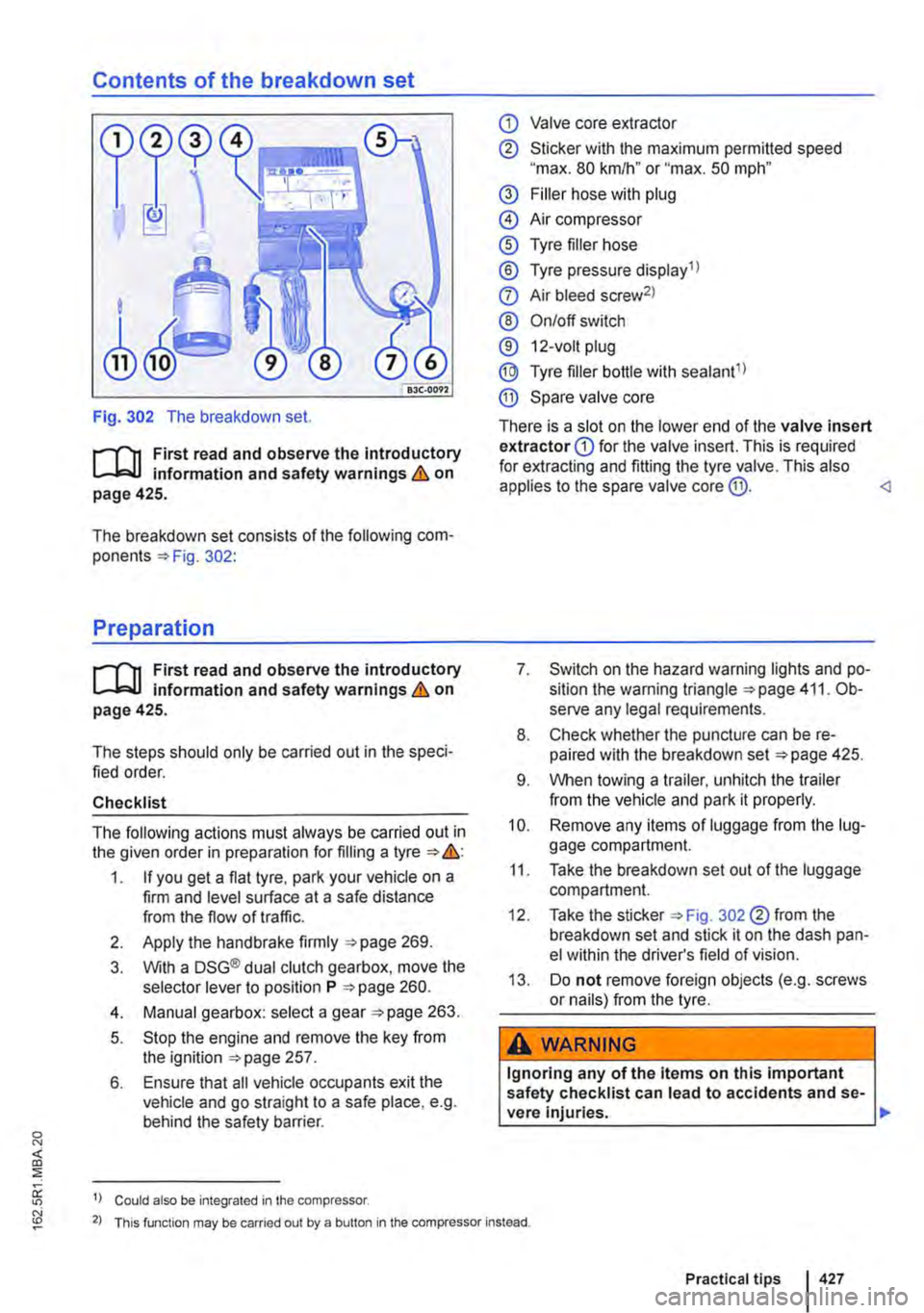
Fig. 302 The breakdown set.
r--T'n First read and observe the introductory L-L::.U information and safety warnings & on page 425.
The breakdown set consists of the following com-ponents 302:
Preparation
r--T'n First read and observe the introductory L-L::.U information and safety warnings & on page 425.
The steps should only be carried out in the speci-fied order.
Checklist
The following actions must always be carried out in the given order in preparation for filling a tyre &:
1. If you get a flat tyre, park your vehicle on a firm and level surface at a safe distance from the flow of traffic.
2. Apply the handbrake firmly 269.
3. With a DSG® dual clutch gearbox, move the selector lever to position P 260.
4. Manual gearbox: select a gear 263.
5. Stop the engine and remove the key from the ignition 257.
6. Ensure that all vehicle occupants exit the vehicle and go straight to a safe place, e.g. behind the safety barrier.
1) Could also be integrated in the compressor.
CD Valve core extractor
® Sticker with the maximum permitted speed "max. 80 km/h" or "max. 50 mph"
@ Filler hose with plug
@ Air compressor
® Tyre filler hose
® Tyre pressure display 1 l
0 Air bleed screw2l
® On/off switch
® 12-volt plug
@ Tyre filler bottle with sealant1l
® Spare valve core
There is a slot on the lower end of the valve insert extractor CD for the valve insert. This is required for extracting and fitting the tyre valve. This also applies to the spare valve core @.
8. Check whether the puncture can be re-paired with the breakdown set 425.
9. When towing a trailer, unhitch the trailer from the vehicle and park it properly.
10. Remove any items of luggage from the lug-gage compartment.
11. Take the breakdown set out of the luggage compartment.
12. Take the sticker 302 ®from the breakdown set and stick it on the dash pan-el within the driver's field of vision.
13. Do not remove foreign objects (e.g. screws or nails) from the tyre.
A WARNING
Ignoring any of the items on this important safety checklist can lead to accidents and se-vere Injuries. ,..
2) This function may be carried out by a button in the compressor instead.
Practical tips 427