Page 456 of 552
456 5-2. Steps to take in an emergency
VERSO-S_EE
The compact spare tire
The compact spare tire is identified by the label “TEMPORARY USE
ONLY” on the tire sidewall.
Use the compact spare tire temporarily, and only in an emergency.
Make sure to check the tire inflation pressure of the compact spare tire.
(P. 523)
If you have a flat front tire on a road covered with snow or ice
Install the compact spare tire on one of the rear wheels of the vehicle. Per-
form the following steps and fit tire chains to the front tires:
Replace a rear tire with the compact spare tire.
Replace the flat front tire with the tire removed from the rear of the
vehicle.
Fit tire chains to the front tires.
When reinstalling the wheel ornament (vehicles with steel wheels)
STEP1
STEP2
STEP3
Align the cutout of the wheel ornament
with the valve stem as shown the illustra-
tion.
Page 469 of 552
5
469 5-2. Steps to take in an emergency
When trouble arises
VERSO-S_EEConnect the bottle to the com-
pressor.
As shown in the illustration, insert
the bottle vertically into the com-
pressor to connect making sure
that the claw on the bottle's neck
is hooked onto the cutout of the
compressor case.
Check the specified tire inflation
pressure.
Tire inflation pressure is speci-
fied on the label in the glove box.
(P. 523)
Start the vehicle’s engine.
To inject the sealant and inflate
the tire, turn the compressor
switch on.
STEP10
STEP11
STEP12
STEP13
Page 470 of 552

470 5-2. Steps to take in an emergency
VERSO-S_EEInflate the tire until the specified
air pressure is reached.
The sealant will be injected
and the pressure will surge
and then gradually decrease.
The air pressure gauge will
display the actual tire inflation
pressure about 1 minute (5
minutes at low temperature)
after the switch is turned on.
Inflate the tire until the speci-
fied air pressure.
• Turn the compressor switch off
and then check the tire inflation
pressure. Being careful not to
over inflate, check and repeat
the inflation procedure until the
specified tire inflation pressure
is reached.
• If the tire inflation pressure is
still lower than the specified
point after inflation for 35 min-
utes with the switch on, the tire
is too damaged to be repaired.
Turn the compressor switch off
and contact any authorized
Toyota dealer or repairer, or
another duly qualified and
equipped professional.
• If the tire inflation pressure
exceeds the specified air pres-
sure, let out some air to adjust
the tire inflation pressure.
(P. 473, 523)
STEP14
Page 472 of 552

472 5-2. Steps to take in an emergency
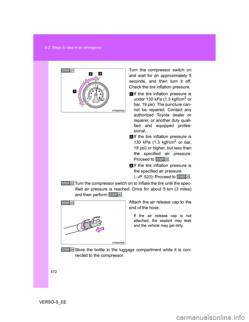
VERSO-S_EETurn the compressor switch on
and wait for an approximately 5
seconds, and then turn it off.
Check the tire inflation pressure.
If the tire inflation pressure is
under 130 kPa (1.3 kgf/cm
2 or
bar, 19 psi): The puncture can-
not be repaired. Contact any
authorized Toyota dealer or
repairer, or another duly quali-
fied and equipped profes-
sional.
If the tire inflation pressure is
130 kPa (1.3 kgf/cm
2 or bar,
19 psi) or higher, but less than
the specified air pressure:
Proceed to .
If the tire inflation pressure is
the specified air pressure
(P. 523): Proceed to .
Turn the compressor switch on to inflate the tire until the spec-
ified air pressure is reached. Drive for about 5 km (3 miles)
and then perform .
Attach the air release cap to the
end of the hose.
If the air release cap is not
attached, the sealant may leak
and the vehicle may get dirty.
Store the bottle in the luggage compartment while it is con-
nected to the compressor.
STEP21
STEP22
STEP23
STEP22
STEP20
STEP23
STEP24
Page 473 of 552

5
473 5-2. Steps to take in an emergency
When trouble arises
VERSO-S_EETaking precautions to avoid sudden braking, sudden accelera-
tion and sharp turns, drive carefully at under 80 km/h (50
mph) to the nearest authorized Toyota dealer or repairer, or
another duly qualified and equipped professional for tire repair
or replacement.
If the tire is inflated to more than the specified air pressure
Disconnect the hose from the valve.
Disconnect the hose from the valve, remove the air release cap
from the hose and then reconnect the hose.
Turn the compressor switch on and wait for several seconds, and
then turn it off. Check that the air pressure indicator shows the
specified air pressure.
If the air pressure is under the designated pressure, turn the com-
pressor switch on again and repeat the inflation procedure until the
specified air pressure is reached.
The valve of a tire that has been repaired
After a tire is repaired with the emergency tire puncture repair kit, the valve
should be replaced.
Note for checking the emergency tire puncture repair kit
Check the sealant expiry date occasionally.
The expiry date is shown on the bottle. Do not use sealant whose expiry
date has already passed. Otherwise, repairs conducted using the emer-
gency tire puncture repair kit may not be performed properly.
STEP25
STEP1
Install the air release cap to the end of the
hose and push the protrusion on the air
release cap into the tire valve to let some
air out.STEP2
STEP3
STEP4
Page 476 of 552

476 5-2. Steps to take in an emergency
VERSO-S_EE
CAUTION
When fixing the flat tire
After inflation of the tire has completed, the sealant may splatter when the
hose is disconnected or some air is let out of the tire.
Follow the operation procedure to repair the tire. If the procedures not fol-
lowed, the sealant may spray out.
Keep back from the tire while it is being repaired, as there is a chance of it
bursting while the repair operation is being performed. If you notice any
cracks or deformation of the tire, turn off the compressor switch and stop
the repair operation immediately.
The repair kit may overheat if operated for a long period of time. Do not
operate the repair kit continuously for more than 40 minutes.
Parts of the repair kit become hot during operation. Be careful when han-
dling the repair kit during and after operation. Do not touch the metal part
around the connecting area between the bottle and compressor. It will be
extremely hot.
Do not attach the vehicle speed warning sticker to an area other than the
one indicated. If the sticker is attached to an area where an SRS airbag is
located, such as the pad of the steering wheel, it may prevent the SRS air-
bag from operating properly.
Driving to spread the liquid sealant evenly
Observe the following precautions to reduce the risk of accidents.
Failing to do so may result in a loss of vehicle control and cause death or
serious injury.
Drive the vehicle carefully at a low speed. Be especially careful when turn-
ing and cornering.
If the vehicle does not drive straight or you feel a pull through the steering
wheel, stop the vehicle and check the following.
• Tire condition. The tire may have separated from the wheel.
• Tire inflation pressure. If the tire inflation pressure is 130 kPa (1.3
kgf/cm
2 or bar, 19 psi) or less, the tire may be severely damaged.
Page 523 of 552
523 6-1. Specifications
6
Vehicle specifications
VERSO-S_EE
Tires and wheels
Tire size185/65R15 88H, 185/60R16 86H,
T135/70D16 100M
Tire inflation pressure
(Recommended cold tire
inflation pressure)230 kPa (2.3 kgf/cm2 or bar, 33 psi)
Tire inflation pressure
(compact spare)
(Recommended cold tire
inflation pressure)420 kPa (4.2 kgf/cm
2 or bar, 60 psi)
Wheel size15 5 1/2 J, 16 5 1/2 J, 16 4T (compact
spare)
Wheel nut torque 103 N•m (10.5 kgf•m, 76 ft•lbf)
Page 545 of 552

545 Alphabetical index
VERSO-S_EE
Seats
Adjustment .............................. 69
Adjustment precautions .......... 69
Child seats/child restraint
system installation .............. 135
Cleaning ................................ 356
Head restraint ......................... 75
Properly sitting in the seat..... 110
Rear seat adjustment .............. 70
Rear seat adjustment
precautions ........................... 73
Seat heaters.......................... 335
Service reminder
indicators .............................. 201
Shift lever
If the shift lever cannot
be shifted ............................ 482
Manual transmission ............. 189
Multidrive............................... 178
Multi-mode manual
transmission ....................... 184
Shift lock system ............. 481, 482
Side airbags ............................. 112
Side mirror
Adjusting and folding............... 88
Smart entry & start system
Entry function .......................... 33
Starting the engine ................ 164
Spare tire
Inflation pressure .................. 523
Storage location .................... 448Spark plug ................................ 519
Specifications .......................... 510
Speedometer ............................ 195
Steering
Column lock release ..... 171, 176
Steering wheel
Adjustment .............................. 84
Audio switches ...................... 317
Stop & Start cancel switch ..... 228
Stop & Start system ................ 226
Stop & Start system
operation time ....................... 196
Stop & Start system total
operation time ....................... 197
Stop lights
Replacing light bulbs............. 413
Wattage ................................ 524
Storage feature ........................ 323
Storage precautions ................ 245
Stuck
If your vehicle becomes
stuck ................................... 504
Sun visors ................................ 329
*: Refer to ““touch screen” Owner’s manual”.