2013 SUBARU TRIBECA ignition
[x] Cancel search: ignitionPage 221 of 420

6-2Interior equipment/Interior light
Interior light
When leaving your vehicle, make sure the
lights are turned off to avoid batterydischarge. &Dome light
Models with Rear Seat Entertainment
Models without Rear Seat Entertainment
1) ON
2) DOOR
3) OFF
The dome light switch has the following
three positions. ON: The light remains on continuously.
OFF: The light remains off.
DOOR: The dome light illuminates auto-
matically in the following cases. . Any of the doors or the rear gate is
opened.. The doors or the rear gate are un-
locked using the remote keyless entry
transmitter. . The ignition switch is turned from the
“ Acc ”position to the “LOCK ”position. The automatically illuminated dome light
remains on for several seconds and then
gradually turns off after all doors and the
rear gate are closed. While the light is
illuminated, if any of the following opera-
tions are performed, the dome light turns
off immediately. .
The ignition switch is turned from the
“ LOCK ”position to “Acc ”or “ON ”position.
. All doors and the rear gate are locked
using the remote keyless entry transmitter.
The setting of the period for which the light
remains on (OFF delay timer) can be
changed by a SUBARU dealer. Contact
the nearest SUBARU dealer for details.
Page 223 of 420

6-4Interior equipment/Sun visors
(automatic illumination - ON).
. The doors are unlocked using the
remote keyless entry transmitter. . The ignition switch is turned from the
“ Acc ”position to the “LOCK ”position.
The automatically illuminated map lights
remain illuminated for several seconds
and then gradually turn off after all doors
are closed.
While the lights are illuminated, if any of
the following operations are performed,
the map lights turn off immediately. . The ignition switch is turned from the
“ LOCK ”position to the “Acc ”or “ON ”
position.. All doors and the rear gate are locked
using the remote keyless entry transmitter.
The setting of the period for which the light
remains illuminated (OFF delay timer) can
be changed by a SUBARU dealer. Con-
tact your SUBARU dealer for details.
NOTE
If any of the doors or the rear gate is
not completely closed, the map lights
will remain illuminated as a result.
However, the map lights are automati-
cally turned off by the battery drainage
prevention functi on to prevent the
battery from discharging. For details, refer to
“Battery drainage prevention
function ”F 2-6.
& Automatic ambient light for
center console area (if equipped)
The automatic ambient light illuminates
when the ignition switch is in the “ON ”
position and the light control switch is inthe “
”position or “”position. The
light dimly illuminates the area around the
center console. The light turns off when
the light control switch is in the “OFF ”
position. Also, the brightness of the light is
adjusted by the illumination brightness
control dial. Sun visors
To block out glare, swing down the visors.
To use the sun visor at a side window,
swing it down and move it sideways.
Page 229 of 420
6-10Interior equipment/Accessory power outlets
trim can be used to hold beverage bottles
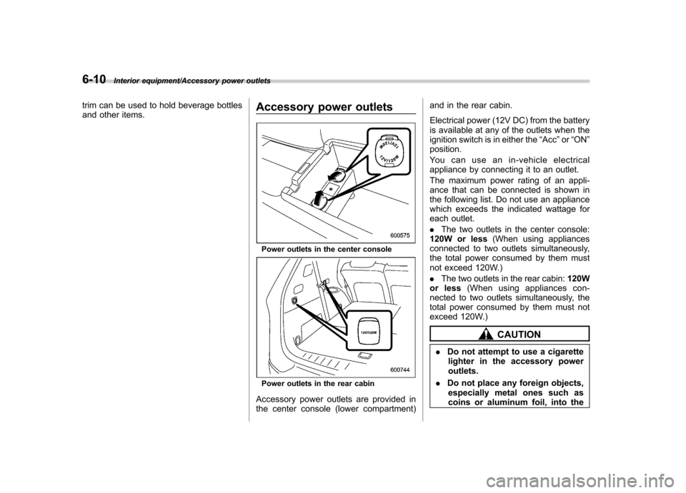
and other items.Accessory power outlets
Power outlets in the center console
Power outlets in the rear cabin
Accessory power outlets are provided in
the center console (lower compartment) and in the rear cabin.
Electrical power (12V DC) from the battery
is available at any of the outlets when the
ignition switch is in either the
“Acc ”or “ON ”
position.
You can use an in-vehicle electrical
appliance by connecting it to an outlet.
The maximum power rating of an appli-
ance that can be connected is shown in
the following list. Do not use an appliance
which exceeds the indicated wattage for
each outlet. . The two outlets in the center console:
120W or less (When using appliances
connected to two outlets simultaneously,
the total power consumed by them must
not exceed 120W.) . The two outlets in the rear cabin: 120W
or less (When using appliances con-
nected to two outlets simultaneously, the
total power consumed by them must not
exceed 120W.)
CAUTION
. Do not attempt to use a cigarette
lighter in the accessory power outlets.
. Do not place any foreign objects,
especially metal ones such as
coins or aluminum foil, into the
Page 240 of 420
opener by pressing the programmed HomeLink®button.
& Programming other devices
To program other devices such as door
locks, home lighting and security systems,
contact HomeLink at www.homelink.com
or call 1-800-355-3515. & Operating the HomeLink
®
Wireless Control System
Once programmed, the HomeLink
®Wire-
less Control System can be used to
remote-control the devices to which its
buttons are programmed. To activate a
device, simply press the appropriate but-
ton. The indicator light illuminates, indicat-
ing that the signal is being transmitted.
& Erasing HomeLink
®button
memory
NOTE . Performing this procedure erases
the memory of all the preprogrammed
buttons simultaneously. The memory
of individual buttons cannot be erased. . It is recommended that upon the
sale of the vehicle, the memory of all
programmed HomeLink
®buttons be
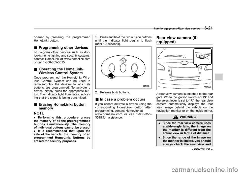
erased for security purposes. 1. Press and hold the two outside buttons
until the indicator light begins to flash
(after 10 seconds).
2. Release both buttons. &
In case a problem occurs
If you cannot activate a device using the
corresponding HomeLink
®button after
programming, contact HomeLink at
www.homelink.com or call 1-800-355-
3515 for assistance. Rear view camera (if
equipped)
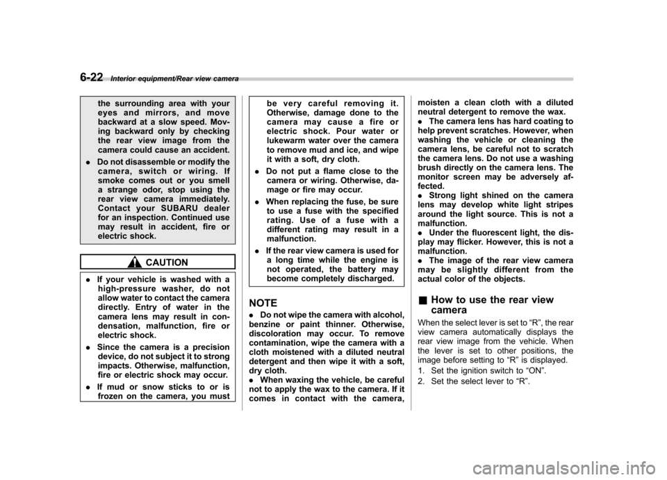
A rear view camera is attached to the rear
gate. When the ignition switch is
“ON ”and
the select lever is set to “R ”, the rear view
camera automatically displays the rear
view image behind the vehicle on the
navigation monitor or on the inside mirror.
WARNING
. Since the rear view camera uses
a wide-angle lens, the image on
the monitor is different from the
actual view in terms of distance.
. Since the range of the image on
the monitor is limited, you should
always check the rear view and
Interior equipment/Rear view camera6-21
– CONTINUED –
Page 241 of 420
6-22Interior equipment/Rear view camera
the surrounding area with your
eyes and mirrors, and move
backward at a slow speed. Mov-
ing backward only by checking
the rear view image from the
camera could cause an accident.
. Do not disassemble or modify the
camera, switch or wiring. If
smoke comes out or you smell
a strange odor, stop using the
rear view camera immediately.
Contact your SUBARU dealer
for an inspection. Continued use
may result in accident, fire or
electric shock.
CAUTION
. If your vehicle is washed with a
high-pressure washer, do not
allow water to contact the camera
directly. Entry of water in the
camera lens may result in con-
densation, malfunction, fire or
electric shock.
. Since the camera is a precision
device, do not subject it to strong
impacts. Otherwise, malfunction,
fire or electric shock may occur.
. If mud or snow sticks to or is
frozen on the camera, you must be very careful removing it.
Otherwise, damage done to the
camera may cause a fire or
electric shock. Pour water or
lukewarm water over the camera
to remove mud and ice, and wipe
it with a soft, dry cloth.
. Do not put a flame close to the
camera or wiring. Otherwise, da-
mage or fire may occur.
. When replacing the fuse, be sure
to use a fuse with the specified
rating. Use of a fuse with a
different rating may result in amalfunction.
. If the rear view camera is used for
a long time while the engine is
not operated, the battery may
become completely discharged.
NOTE . Do not wipe the camera with alcohol,
benzine or paint thinner. Otherwise,
discoloration may occur. To remove
contamination, wipe the camera with a
cloth moistened with a diluted neutral
detergent and then wipe it with a soft,
dry cloth.. When waxing the vehicle, be careful
not to apply the wax to the camera. If it
comes in contact with the camera, moisten a clean cloth with a diluted
neutral detergent to remove the wax..
The camera lens has hard coating to
help prevent scratches. However, when
washing the vehicle or cleaning the
camera lens, be careful not to scratch
the camera lens. Do not use a washing
brush directly on the camera lens. The
monitor screen may be adversely af-fected.. Strong light shined on the camera
lens may develop white light stripes
around the light source. This is not amalfunction.. Under the fluorescent light, the dis-
play may flicker. However, this is not a malfunction. . The image of the rear view camera
may be slightly different from the
actual color of the objects. & How to use the rear view camera
When the select lever is set to “R ”, the rear
view camera automatically displays the
rear view image from the vehicle. When
the lever is set to other positions, the
image before setting to “R ”is displayed.
1. Set the ignition switch to “ON ”.
2. Set the select lever to “R ”.
Page 252 of 420
Preparing to drive
You should perform the following checks
and adjustments every day before you
start driving.
1. Check that all windows, mirrors, and
lights are clean and unobstructed.
2. Check the appearance and condition
of the tires. Also check tires for properinflation.
3. Look under the vehicle for any sign of leaks.
4. Check that the hood and rear gate are
fully closed.
5. Check the adjustment of the seat.
6. Check the adjustment of the inside
and outside mirrors.
7. Fasten your seatbelt. Check that your
passengers have fastened their seatbelts.
8. Check the operation of the warning
and indicator lights when the ignition
switch is turned to the“ON ”position.
9. Check the gauges, indicator and warn-
ing lights after starting the engine.
NOTE
Engine oil, engine coolant, brake fluid,
washer fluid and other fluid levels
should be checked daily, weekly or at
fuel stops. Starting the engine
CAUTION
. Do not operate the starter motor
continuously for more than 10
seconds. If the engine fails to
start after operating the starter
for 5 to 10 seconds, wait for 10
seconds or more before tryingagain.
. If you restart the engine while the
vehicle is moving, shift the select
lever into the “N ” position. Do
not attempt to place the select
lever of a moving vehicle into the“ P ” position.
1. Apply the parking brake.
2. Turn off unnecessary lights and ac- cessories.
3. Shift the select lever to the “P ” or “N ”
position (preferably “P ” position). The
starter will only operate when the select
lever is at the “P ”or “N ”position.
4. Turn the ignition switch to the “ON ”
position and check the operation of the
warning and indicator lights. Refer to“ Warning and indicator lights ”F 3-9.
5. Turn the ignition switch to the “START ”
position without depressing the accelera- tor pedal. Release the key immediately
after the engine has started.
If the engine does not start, try the following.
(1) Turn the ignition switch to the“LOCK ”position and wait for at least
10 seconds. After checking that the
parking brake is firmly set, turn the
ignition switch to the “START ”position
while depressing the accelerator pedal
slightly (approximately a quarter of the
full stroke). Release the accelerator
pedal as soon as the engine starts.
(2) If this fails to start the engine, turn
the ignition switch back to the “LOCK ”
position and wait for at least 10
seconds. Then fully depress the accel-
erator pedal and turn the ignition
switch to the “START ”position. If the
engine starts, quickly release the
accelerator pedal.
(3) If this fails to start the engine, turn
the ignition switch again to the “LOCK ”
position. After waiting for 10 seconds
or longer, turn the ignition switch to the“ START ”position without depressing
the accelerator pedal.
(4) If the engine still refuses to start,
contact your nearest SUBARU dealer
for assistance.
6. Confirm that all warning and indicator
lights have turned off after the engine has
Starting and operating/Preparing to drive7-7
– CONTINUED –
Page 253 of 420
7-8Starting and operating/Stopping the engine
started. The fuel injection system auto-
matically lowers the idle speed as the
engine warms up.
While the engine is warming up, make
sure that the select lever is at the“P ” or
“ N ”position and that the parking brake is
applied. NOTE . The engine may be difficult to start
when the battery has been discon-
nected and reconnected (for mainte-
nance or other purposes). This diffi-
culty is caused by the electronically
controlled throttle ’s self-diagnosis
function. To overcome it, keep the
ignition switch in the “ON ”position
for approximately 10 seconds before
starting the engine.. To protect the engine while the
select lever is in the “P ” or “N ”
position, the engine is controlled so
that the engine speed may not become
too high even if the accelerator pedal is
depressed hard. Stopping the engine
WARNING
Do not stop the engine when the
vehicle is moving. This will cause
loss of power to the power steering
and the brake booster, making steer-
ing and braking more difficult. It
could also result in accidental acti-
vation of the “LOCK ”position on the
ignition switch, causing the steering
wheel to lock.
The ignition switch should be turned off
only when the vehicle is stopped and the
engine is idling. Remote engine start system
(dealer option)
WARNING
. Do not start the engine using the
remote start system in an en-
closed environment (e.g. closed
garage). Prolonged operation of
a motor vehicle in an enclosed
environment can cause a harmful
build-up of Carbon Monoxide.
Carbon Monoxide is harmful to
your health. Exposure to high
levels of Carbon Monoxide can
cause headaches, dizziness or in
extreme cases unconsciousness
and/or death.
. Before performing any servicing
of the vehicle, temporarily place
the remote engine start system in
service mode to prevent the
system from unexpectedly start-
ing the engine.
Page 254 of 420
&Starting your vehicle
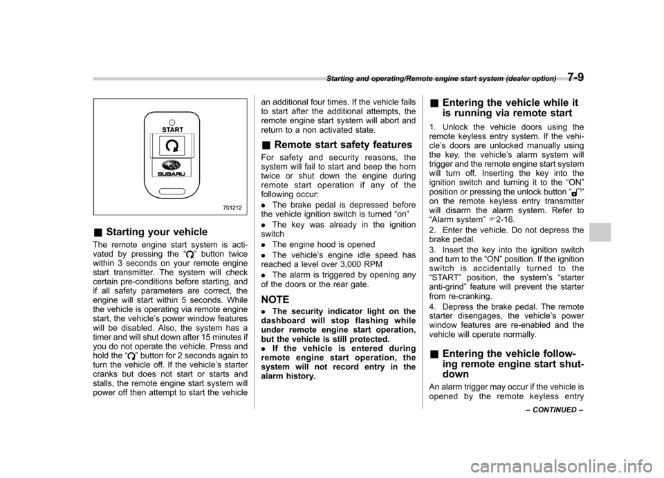
The remote engine start system is acti-
vated by pressing the “
”button twice
within 3 seconds on your remote engine
start transmitter. The system will check
certain pre-conditions before starting, and
if all safety parameters are correct, the
engine will start within 5 seconds. While
the vehicle is operating via remote engine
start, the vehicle ’s power window features
will be disabled. Also, the system has a
timer and will shut down after 15 minutes if
you do not operate the vehicle. Press and
hold the “
”button for 2 seconds again to
turn the vehicle off. If the vehicle ’s starter
cranks but does not start or starts and
stalls, the remote engine start system will
power off then attempt to start the vehicle an additional four times. If the vehicle fails
to start after the additional attempts, the
remote engine start system will abort and
return to a non activated state.
& Remote start safety features
For safety and security reasons, the
system will fail to start and beep the horn
twice or shut down the engine during
remote start operation if any of the
following occur: . The brake pedal is depressed before
the vehicle ignition switch is turned “on ”
. The key was already in the ignition
switch. The engine hood is opened
. The vehicle ’s engine idle speed has
reached a level over 3,000 RPM. The alarm is triggered by opening any
of the doors or the rear gate.
NOTE . The security indicator light on the
dashboard will stop flashing while
under remote engine start operation,
but the vehicle is still protected.. If the vehicle is entered during
remote engine start operation, the
system will not record entry in the
alarm history. &
Entering the vehicle while it
is running via remote start
1. Unlock the vehicle doors using the
remote keyless entry system. If the vehi-cle ’s doors are unlocked manually using
the key, the vehicle ’s alarm system will
trigger and the remote engine start system
will turn off. Inserting the key into the
ignition switch and turning it to the “ON ”
position or pressing the unlock button “
”
on the remote keyless entry transmitter
will disarm the alarm system. Refer to“ Alarm system ”F 2-16.
2. Enter the vehicle. Do not depress the
brake pedal.
3. Insert the key into the ignition switch
and turn to the “ON ”position. If the ignition
switch is accidentally turned to the“ START ”position, the system ’s “starter
anti-grind ”feature will prevent the starter
from re-cranking.
4. Depress the brake pedal. The remote
starter disengages, the vehicle ’s power
window features are re-enabled and the
vehicle will operate normally.
& Entering the vehicle follow-
ing remote engine start shut-down
An alarm trigger may occur if the vehicle is
opened by the remote keyless entry
Starting and operating/Remote engine start system (dealer option)7-9
– CONTINUED –