2013 SUBARU FORESTER steering wheel
[x] Cancel search: steering wheelPage 75 of 436
1-50Seat, seatbelt and SRS airbags
A hands-free microphone or
other accessory in such a loca-
tion could be propelled through
the cabin with great force by the
curtain airbag, or it could prevent
correct deployment of the curtain
airbag. In either case, the result
could be serious injuries.
. Never hang or place coat hangers
or other hard or pointed objects
near the side windows. If such
items are present when the SRS
curtain airbags deploy, they
could be thrown through the
passenger compartment and
cause serious injuries. They
could also prevent proper opera-
tion of the SRS curtain airbags.WARNING
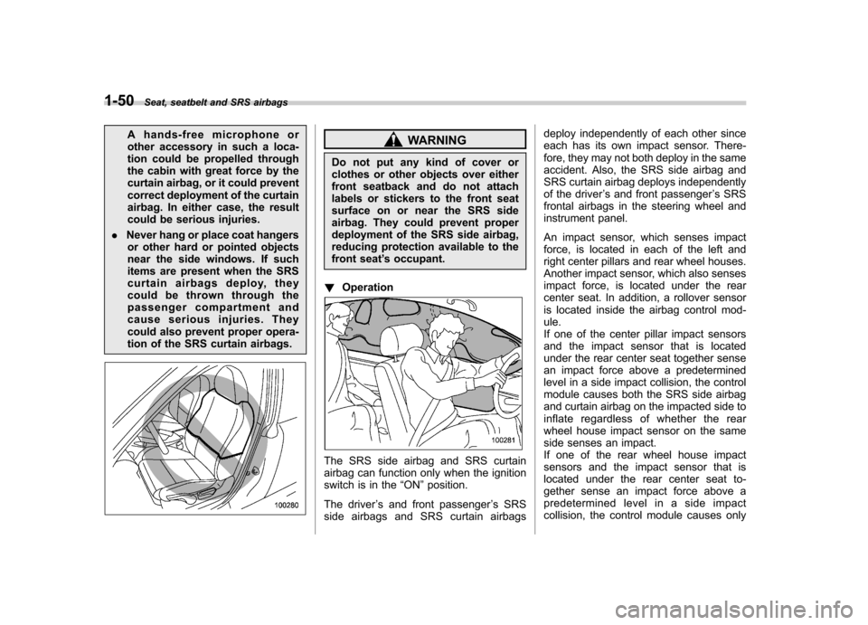
Do not put any kind of cover or
clothes or other objects over either
front seatback and do not attach
labels or stickers to the front seat
surface on or near the SRS side
airbag. They could prevent proper
deployment of the SRS side airbag,
reducing protection available to the
front seat ’s occupant.
! Operation
The SRS side airbag and SRS curtain
airbag can function only when the ignition
switch is in the “ON ”position.
The driver ’s and front passenger ’s SRS
side airbags and SRS curtain airbags deploy independently of each other since
each has its own impact sensor. There-
fore, they may not both deploy in the same
accident. Also, the SRS side airbag and
SRS curtain airbag deploys independently
of the driver
’s and front passenger ’s SRS
frontal airbags in the steering wheel and
instrument panel.
An impact sensor, which senses impact
force, is located in each of the left and
right center pillars and rear wheel houses.
Another impact sensor, which also senses
impact force, is located under the rear
center seat. In addition, a rollover sensor
is located inside the airbag control mod-ule.
If one of the center pillar impact sensors
and the impact sensor that is located
under the rear center seat together sense
an impact force above a predetermined
level in a side impact collision, the control
module causes both the SRS side airbag
and curtain airbag on the impacted side to
inflate regardless of whether the rear
wheel house impact sensor on the same
side senses an impact.
If one of the rear wheel house impact
sensors and the impact sensor that is
located under the rear center seat to-
gether sense an impact force above a
predetermined level in a side impact
collision, the control module causes only
Page 83 of 436
1-58Seat, seatbelt and SRS airbags
.No illumination of the warning
light when the ignition switch is
first turned to the “ON ”position
. Continuous illumination of the
warning light
. Illumination of the warning light
while driving
& SRS airbag system servicing
WARNING
. When discarding an airbag mod-
ule or scrapping the entire vehi-
cle damaged by a collision, con-
sult your SUBARU dealer.
. The SRS airbag has no user-
serviceable parts. Do not use
electrical test equipment on any
circuit related to the SRS airbag
system. For required servicing of
the SRS airbag, consult your
nearest SUBARU dealer. Tamper-
ing with or disconnecting thesystem ’s wiring could result in
accidental inflation of the SRS
airbag or could make the system
inoperative, which may result in
serious injury.
CAUTION
If you need service or repair in areas
indicated in the following list, have
the work performed by an author-
ized SUBARU dealer. The SRS air-
bag control module, impact sensors
and airbag modules are stored in
these areas. . Under the center console
. On both the right and left sides at
the front of the vehicle
. Steering wheel and column and
nearby areas
. Top of the dashboard on front
passenger ’s side and nearby
areas
. Each front seat and nearby area
. Inside each center pillar
. In each roof side (from the front
pillar to a point over the rear seat)
. Between the rear seat cushion
and rear wheel house on each side
. Under the rear center seat
In the event that the SRS airbag is
deployed, replacement of the system
should be performed only by an author-
ized SUBARU dealer. When the compo- nents of the SRS airbag system are
replaced, use only genuine SUBARUparts.
NOTE
In the following cases, contact your
SUBARU dealer as soon as possible. . The front part of the vehicle was
damaged in an accident in which either
or both of the frontal airbags did not
deploy.. The pad of the steering wheel, the
cover over the front passenger ’s SRS
frontal airbag, or either roof side (from
the front pillar to a point over the rear
seat) is scratched, cracked, or other-
wise damaged.. Center pillar, rear wheel house or
rear sub frame, or an area near these
parts, was involved in an accident in
which the SRS side airbag and SRS
curtain airbag did not deploy.. The fabric or leather of either front
seatback is cut, frayed, or otherwisedamaged.. The rear part of the vehicle was
involved in an accident in which no
SRS airbag deployed.
Page 84 of 436
&Precautions against vehicle modification
WARNING
To avoid accidental activation of the
system or rendering the system
inoperative, which may result in
serious injury, no modifications
should be made to any components
or wiring of the SRS airbag system.
This includes the following modifi- cations. . Installation of custom steering
wheels
. Attachment of additional trim
materials to the dashboard
. Installation of custom seats
. Replacement of seat fabric or
leather
. Installation of additional fabric or
leather on the front seat
. Attachment of a hands-free mi-
crophone or any other accessory
to a front pillar, a center pillar, a
rear pillar, the windshield, a side
window, an assist grip, or any
other cabin surface that would be
near a deploying SRS curtainairbag. .
Installation of additional electri-
cal/electronic equipment such as
a mobile two-way radio on or
near the SRS airbag system
components and/or wiring is not
advisable. This could interfere
with proper operation of the
SRS airbag system.
CAUTION
Do not perform any of the following
modifications. Such modifications
can interfere with proper operation
of the SRS airbag system. . Attachment of any equipment
(bush bar, winches, snow plow,
skid plate, etc.) other than genu-
ine SUBARU accessory parts to
the front end.
. Modification of the suspension
system or front end structure.
. Installation of a tire of different
size and construction from the
tires specified on the vehicle
placard attached to the driver ’s
door pillar or specified for indivi-
dual vehicle models in this Own-er ’s Manual.
. Attachment of any equipment
(side steps or side sill protectors, etc.) other than genuine SUBARU
accessory parts to the side body.
Always consult your SUBARU dealer if
you want to install any accessory parts on
your vehicle. Seat, seatbelt and SRS airbags
1-59
Page 113 of 436

Instruments and controlsInformation display ............................................ 3-26
Outside temperature indicator ............................ 3-27
Current fuel consumption (if equipped) ............... 3-27
Average fuel consumption .................................. 3-28
To turn off fuel consumption indicator display ............................................................. 3-28
Light control switch ........................................... 3-29
Headlights. ......................................................... 3-29
High/low beam change (dimmer) ......................... 3-30
Headlight flasher ................................................ 3-30
Daytime running light system (if equipped) ... ...... 3-30
Automatic headlight beam leveler (models with HID headlights) ................................................ 3-31 Turn signal lever
................................................ 3-31
Illumination brightness control ......................... 3-31
Front fog light switch (if equipped) .................. 3-32
Wiper and washer .............................................. 3-33
Windshield wiper and washer switches .............. 3-34
Rear window wiper and washer switch ............... 3-35
Mirrors ................................................................ 3-36
Inside mirror ...................................................... 3-36
Auto-dimming mirror/compass (if equipped) ....... 3-36
Auto-dimming mirror/compass with HomeLink
®(if equipped) .................................................... 3-38
Outside mirrors ................................................. 3-43
Defogger and deicer .......................................... 3-44
Tilt/telescopic steering wheel ........................... 3-46
Horn .................................................................... 3-47
Page 114 of 436
Ignition switch
WARNING
. Never turn the ignition switch to
“ LOCK ”while the vehicle is
being driven or towed because
that will lock the steering wheel,
preventing steering control. In
addition, when the engine is
turned off, it takes a much great-
er effort than usual to steer.
. Before leaving the vehicle, al-
ways remove the key from the
ignition switch for safety and
never allow an unattended child
to remain in the vehicle. Failure
to follow this procedure could
result in injury to a child or
others. Children could operate
the power windows, the moon-
roof or other controls or even
make the vehicle move.
CAUTION
Do not attach a large key holder or
key case to either key. If it bangs
against your knees or hands while
you are driving, it could turn the
ignition switch from the “ON ”posi- tion to the
“Acc ”or “LOCK ”posi-
tion, thereby stopping the engine.
Also, if the key is attached to a
keyholder or to a large bunch of
other keys, centrifugal force may act
on it as the vehicle moves, resulting
in unwanted turning of the ignitionswitch.
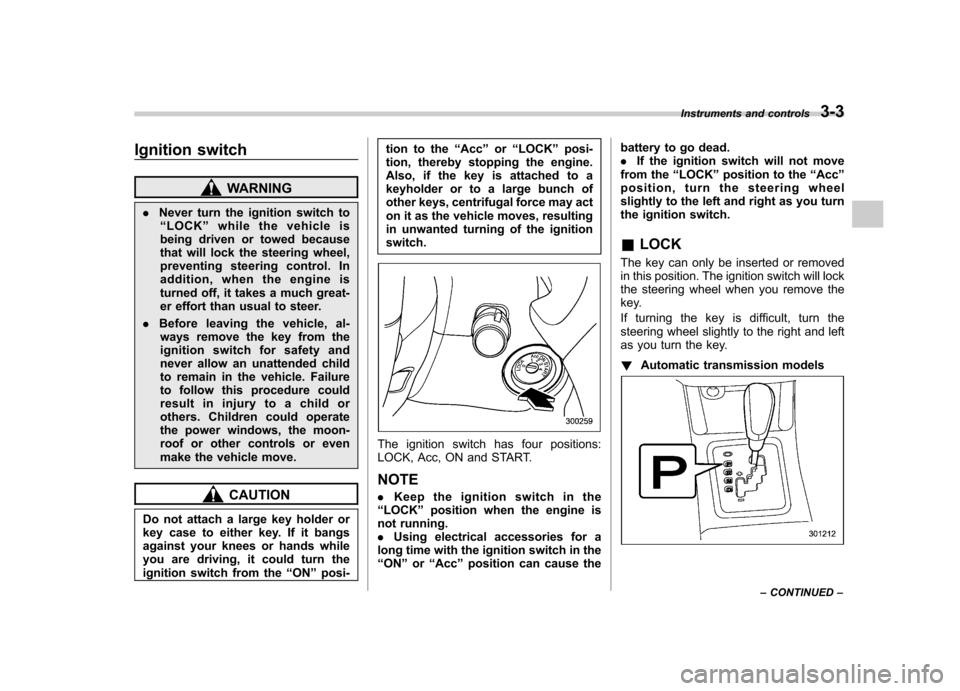
The ignition switch has four positions:
LOCK, Acc, ON and START. NOTE . Keep the ignition switch in the
“ LOCK ”position when the engine is
not running. . Using electrical accessories for a
long time with the ignition switch in the“ ON ”or “Acc ”position can cause the battery to go dead..
If the ignition switch will not move
from the “LOCK ”position to the “Acc ”
position, turn the steering wheel
slightly to the left and right as you turn
the ignition switch. & LOCK
The key can only be inserted or removed
in this position. The ignition switch will lock
the steering wheel when you remove the
key.
If turning the key is difficult, turn the
steering wheel slightly to the right and left
as you turn the key. ! Automatic transmission models
Instruments and controls 3-3
– CONTINUED –
Page 157 of 436

3-46Instruments and controls
tinuously for any longer than
necessary.
. Do not use sharp instruments or
window cleaner containing abra-
sives to clean the inner surface
of the rear window. They may
damage the conductors printed
on the window.
NOTE . Turn on the defogger and deicer
system if the wipers are frozen to the windshield.. If the windshield is covered with
snow, remove the snow so that the
windshield wiper deicer works effec-
tively.. While the defogger and deicer sys-
tem is in the continuous operation
mode, if the vehicle speed remains at
9 mph (15 km/h) or less for 15 minutes,
the windshield wiper deicer automati-
cally stops operating, though the rear
window defogger and outside mirror
defogger maintain continuous opera-
tion in this condition.. While the defogger and deicer sys-
tem is in the continuous operation
mode, if the battery voltage drops
below the permissible level, continu-
ous operation of the defogger and deicer system is canceled and the
system stops operating.
Tilt/telescopic steering wheel
WARNING
. Do not adjust the steering wheel
tilt/telescopic position while driv-
ing. This may cause loss of
vehicle control and result in
personal injury.
. If the lever cannot be raised to
the fixed position, adjust the
steering wheel again. It is dan-
gerous to drive without locking
the steering wheel. This may
cause loss of vehicle control
and result in personal injury.
Page 158 of 436
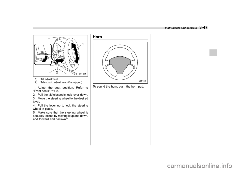
1) Tilt adjustment
2) Telescopic adjustment (if equipped)
1. Adjust the seat position. Refer to “ Front seats ”F 1-2.
2. Pull the tilt/telescopic lock lever down.
3. Move the steering wheel to the desired level.
4. Pull the lever up to lock the steering
wheel in place.
5. Make sure that the steering wheel is
securely locked by moving it up and down,
and forward and backward. Horn
To sound the horn, push the horn pad.
Instruments and controls
3-47
Page 210 of 436
based on the following information. If you
cannot clear those messages, please
contact your SUBARU dealer. !When “CHECK DEVICE ”is dis-
played
This message is displayed under the
following conditions. . When there is a short in the USB bus
. When an unsupported device (for ex-
ample a USB mouse) is connected. When an unsupported iPod
®is con-
nected. When a connected iPod
®is frozen
. When a transmission malfunction oc-
curs. When an iPod
®confirmation malfunc-
tion occurs. When a HUB class USB storage
device is connected
Disconnect the USB storage device/iPod
®
and check it. ! When “NO USB ”is displayed (type
D audio)
This message is displayed under the
following conditions. . No USB storage devices/iPod
®are
connected.. An incompatible USB storage device/
iPod
®is connected. Connect a supported USB storage device/ iPod
®.
! When “No song ”is displayed (type
D audio)
This message is displayed when there are
no playable audio tracks on the connected
USB storage device/iPod
®. Connect a
USB storage device/iPod®that has play-
able audio tracks stored on it. Audio control buttons (if
equipped)
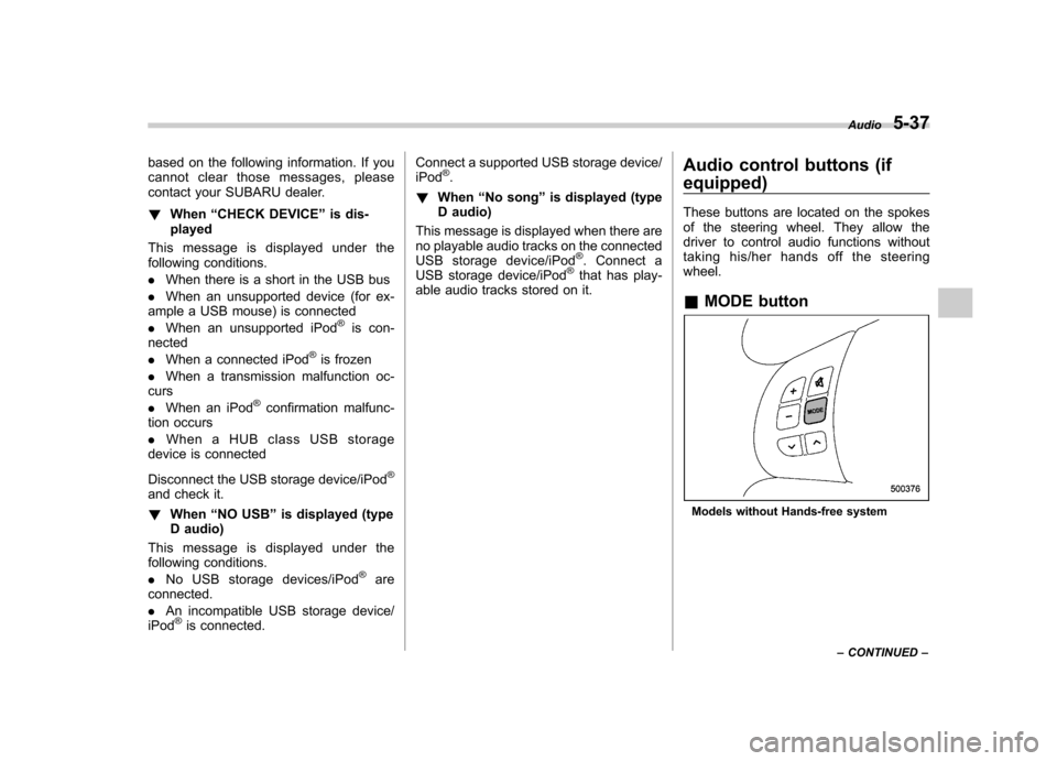
These buttons are located on the spokes
of the steering wheel. They allow the
driver to control audio functions without
taking his/her hands off the steeringwheel. &
MODE button
Models without Hands-free system Audio
5-37
– CONTINUED –