2013 SSANGYONG TURISMO oil pressure
[x] Cancel search: oil pressurePage 251 of 796

06-6
3) Inspection of Turbine
Thoroughly check the followings.
Must absolutely not operate the turbocharger with the compressor outlet and inlet opened as it
could damage the turbocharger or be hazardous during inspection.
Interference: In case where is trace of interference or smallest damage on the compressor wheel
means, most of times, that abrasion has occurred on the journal bearing. Must inspect after the
overhaul.
Oil Leakage: The reason for oil leakage at the compressor section is the air cleaner, clogged by
substances such as dust, causes the compressor inlet negative pressure. -
-
Rotating in high speed at no-load for extended period of time can cause oil leakage to the
compressor section as oil pressure within the center housing gets higher than pressure within
the compressor housing.
Overuse of engine break (especially in low gear) in down hill makes significantly low exhaust gas
energy compared to the time where great amount of air is required during idling conditions of the
engine. Therefore, amount of air in the compressor inlet increases but the turbocharge pressure
is not high, which makes negative a.
b.
No problem will occur with the turbocharger if above conditions are found in early stage but oil
leaked over long period of time will solidify at each section causing to breakout secondary defects.
Damages by foreign materials: In case where the compressor wheel is damaged by foreign materials
requires having an overhaul. At this time, it's necessary to check whether the foreign materials have
contaminated intake/exhaust manifold or inside of engine.
Page 268 of 796

07-31543-00
1. SPECIFICATION
The engine oil filter element should be changed at the same time with the engine oil.
Regularly check the engine oil level and add the engine oil if necessary.
Remember to check the engine oil level and shorten the cycle to replace the engine oil under
severe driving conditions. -
-
Severe Driving Condition
Frequent stop-and-go traffic, extended idling, short driving distance below 6 km, driving distance
below 16 km when the outside temperature remains below freezing
Driving in a hilly or mountainous terrain, sandy, or dusty area
High load driving such as trailer towing
Taxi, patrol service or delivery service (extended idling and excessive driving with low speed) -
-
-
-
Unit Specification
Oil pump Lubrication system Gear pump, forced circulation
Type Inscribed gear
Capacity 63 L at 4,000 rpm
Relief pressure5.8 bar ± 0.3 bar
Oil filter Type Full flow/Paper element
Engine oil Specified oil SAE 5W30 (approved by MB SHEET 229.51)
Capacity (L) Min.: 4.5 L / Max.: 6.0 L
Service
intervalEU Change every 20,000 km or 12 months
(The service interval should be shortened under
severe conditions)
General Change every 15,000 km or 12 months
(The service interval should be shortened under
severe conditions)
Oil injection nozzle Type Piston
Operating pressure 1.5bar
Closing pressure 1.0bar
Oil flow 4 L/min
Oil pressure switch Permissible pressure 10bar
Initial check: 5,000km, and replenish if necessary. Shorten the service interval under severe
conditions. (EU,GEN)
Page 270 of 796

07-51543-00
1. SYSTEM DESCRIPTION
1) Overview
The lubrication system supplies oil to each lubrication section to prevent friction and wear and to
remove heat from the friction part. As the engine runs, frictional heat is generated on each lubrication
section. If this condition persists, the bearing can be burned and stuck.
In other words, it creates an oil film on each sliding surface to convert solid friction to liquid friction in
order to minimize wear and prevent temperature increasing on the friction part.
For the D20DTF engine with no oil pressure switch, the engine ECU receives the low engine oil level
signal from the oil level sensor and communicates with the instrument cluster through the CAN
communication to turn on the warning lamp.
2) Components
Oil coolerOil dipstick gaugeOil pump
Oil filter moduleOil pressure switchOil pan
Page 339 of 796

15-110000-00
2) ECU Control
(1) Function
a. ECU Function
ECU receives and analyzes signals from various sensors and then modifies those signals into
permissible voltage levels and analyzes to control respective actuators.
ECU microprocessor calculates injection period and injection timing proper for engine piston speed
and crankshaft angle based on input data and stored specific map to control the engine power and
emission gas.
Output signal of the ECU microprocessor drives pressure control valve to control the rail pressure and
activates injector solenoid valve to control the fuel injection period and injection timing; so controls
various actuators in response to engine changes. Auxiliary function of ECU has adopted to reduce
emission gas, improve fuel economy and enhance safety, comforts and conveniences. For example,
there are EGR, booster pressure control, autocruise (export only) and immobilizer and adopted CAN
communication to exchange data among electrical systems (automatic T/M and brake system) in the
vehicle fluently. And Scanner can be used to diagnose vehicle status and defectives.
Operating temperature range of ECU is normally -40 to +85°C and protected from factors like
oil, water and electromagnetism and there should be no mechanical shocks.
To control the fuel volume precisely under repeated injections, high current should be applied instantly
so there is injector drive circuit in the ECU to generate necessary current during injector drive stages.
Current control circuit divides current applying time (injection time) into full-in-current-phase and hold-
current-phase and then the injectors should work very correctly under every working condition.
b. Control Function
Controls by operating stages
To make optimum combustion under every operating stage, ECU should calculate proper injection
volume in each stage by considering various factors.
Starting injection volume control
During initial starting, injecting fuel volume will be calculated by function of temperature and engine
cranking speed. Starting injection continues from when the ignition switch is turned to ignition
position to till the engine reaches to allowable minimum speed.
Driving mode control
If the vehicle runs normally, fuel injection volume will be calculated by accelerator pedal travel and
engine rpm and the drive map will be used to match the drivers inputs with optimum engine power. -
-
-
Page 368 of 796

15-40
D. Cooling fan and A/C compressor control
Conditions for cooling fan control ▶
The PWM cooling fan is set by coolant temperature and A/C refrigerant pressure. And, the setting
value in A/T equipped vehicle may vary according to the internal oil temperature. The The engine ECU
controls the PWM cooling fan unit based on various signals to get the optimized temperature during
engine running.
PWM cooling fan control according to coolant temperature and vehicle speed -
The PWM cooling fan starts running
from 89℃ of coolant temperature
PWM cooling fan control according to transmission fluid temperature (A/T)
1. PWM duty under 129℃: 0%
2. PWM duty over 130℃: 94.4% -
PWM cooling fan control according to A/C refrigerant pressure -
PWM duty value sharply increases
when the A/C refrigerant pressure
goes over 10 bar. And, it slowly
decreases when A/C refrigerant
pressure goes down below 14 bar
(A/C compressor OFF). PWM duty
Refrigerant
pressure (bar)under 101℃: The PWM dut
y value
decreases when the vehicle speed
increases
over 105℃: The PWM duty value
is fixed at 94.4% -
-
Page 394 of 796

06-4
No. FUNCTION No. FUNCTION
1 Oil pump 18 Oil supply (to exhaust camshaft)
2 Oil gallery (to oil filter) 19 Oil supply (to intake camshaft)
3 Oil filter 20Oil supply
(to exhaust camshaft bearing)
4 Oil pressure switch 21Oil supply
(to intake camshaft bearing)
5 Main oil gallery 22Oil gallery
(oil supply to exhaust valve tappet)
6 Cylinder head closing cover 23Oil gallery
(oil supply to intake valve tappet)
7 Oil gallery (at chain tensioner) 24 Camshaft closing cover
8 Oil non-return valve 25Ball (φ 8 mm)
9 Chain tensioner 26 Screw plug
10 Vent (chain tensioner) 27 Camshaft adjuster
11Front closing cover (φ 17 mm)28Front closing cover
(intake camshaft)
12Oil gallery
(perpendicular to the shaft)29Front treaded bushing
(exhaust camshaft)
13Ball (φ 6 mm)30 Valve tappe
t
14 Oil spray nozzle (timing chain) aOil gallery
(from oil pump to oil filter)
15 Oil gallery (at cylinder head) b Main oil gallery
16Ball (φ 15 mm)cOil return line
(oil returns to the oil pan when
replacing the filter element)
17Oil restriction inner (φ 4mm)
OIL CIRCULATION ▶
Page 404 of 796

08-6
3. IGNITION SYSTEM OPERATION
This ignition system does not use a conventional distributor and coil. It uses a crankshaft position
sensor input to the Engine Control Module (ECM).
The ECM then determines Electronic Spark Timing (EST) and triggers the electronic ignition system
ignition coil.
This type of distributor less ignition system uses a "waste spark" method of spark distribution. Each
cylinder is paired with the cylinder that is opposite it (2.3L DOHC: 2 - 3 or 1 - 4, 3.2L DOHC: 1 - 6 or 2 -
5 or 3 - 4).
The spark occurs simultaneously in the cylinder coming up on the compression stroke and in the
cylinder coming up on the exhaust stroke.
The cylinder on the exhaust stroke requires very little of the available energy to fire the spark plug.
The remaining energy is available to the spark plug in the cylinder on the compression stroke. These
systems use the EST signal from the ECM to control the EST.
The ECM uses the following information: Engine load (mass air flow sensor, manifold air pressure
sensor).
Engine coolant temperature.
Intake air temperature.
Crankshaft position.
Engine speed (rpm).
1) Electronic Ignition System Ignition Coil
The Electronic Ignition (EI) system ignition coil is located on the cylinder head cover.
The double ended coils receive the signal for the ECM which controls the spark advance. Each
EI system ignition coil provides the high voltage to two spark plugs simultaneously;
3.2L DOHC
T1/1: cylinder 2 and 5
T1/2: cylinder 3 and 4
T1/3: cylinder 1 and 6
The EI system ignition coil is not serviceable and must be replaced as an assembly.
Page 624 of 796

07-94411-01
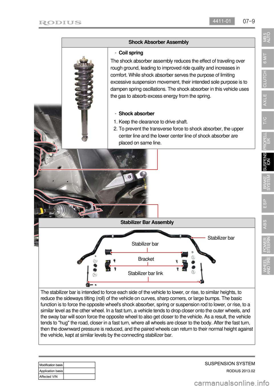
Shock Absorber Assembly
Stabilizer Bar Assembly
The stabilizer bar is intended to force each side of the vehicle to lower, or rise, to similar heights, to
reduce the sideways tilting (roll) of the vehicle on curves, sharp corners, or large bumps. The basic
function is to force the opposite wheel's shock absorber, spring or suspension rod to lower, or rise, to a
similar level as the other wheel. In a fast turn, a vehicle tends to drop closer onto the outer wheels, and
the sway bar will soon force the opposite wheel to also get closer to the vehicle. As a result, the vehicle
tends to "hug" the road, closer in a fast turn, where all wheels are closer to the body. After the fast turn,
then the downward pressure is reduced, and the paired wheels can return to their normal height against
the vehicle, kept at similar levels by the connecting stabilizer bar.
Stabilizer bar
Stabilizer bar
Bracket
Stabilizer bar link
Coil spring -
The shock absorber assembly reduces the effect of traveling over
rough ground, leading to improved ride quality and increases in
comfort. While shock absorber serves the purpose of limiting
excessive suspension movement, their intended sole purpose is to
dampen spring oscillations. The shock absorber in this vehicle uses
the gas to absorb excess energy from the spring.
Shock absorber -
Keep the clearance to drive shaft.
To prevent the transverse force to shock absorber, the upper
center line and the lower center line of shock absorber are
placed on same line. 1.
2.