2013 SSANGYONG NEW ACTYON SPORTS heating
[x] Cancel search: heatingPage 250 of 751

15-50
E. Cautions
Use only specified Engine Oil (approved by MB Sheet 229.51) for CDPF. -
Use only specified engine oil (Low Ash Oil) ▶
The vehicle equipped with CDPF should use specific engine oil to improve the engine performance
and fuel economy, and ensure the service life of CDPF. -
Issue with normal engine oil ▶
Sulfur, one of the contents of engine oil is burned and generates soot that is not regenerated by the
DPF. This remains on the filter as ashes and keeps accumulating. Eventually, this ashes will block
the filter. -
Benefit for specified engine oil ▶
Minimized the sulfur content of engine oil which reduces the service life.
Improved fuel economy and emission level of CO2 with high performance and low viscosity.
Increased service life of engine oil with high resistance to temperature. -
-
-
Problems when using unspecified engine oil ▶
The service life of filter may be reduced by 30% or more by the ashes accumulated on the filter.
The fuel economy may be reduced because of engine rolling resistance, frequent regeneration of
DPF. -
-
These problems are also caused by oil with high sulfur content, such as tax exemption oil and
heating oil, etc. *
Page 274 of 751

02-52211-06
1. FUEL SYSTEM
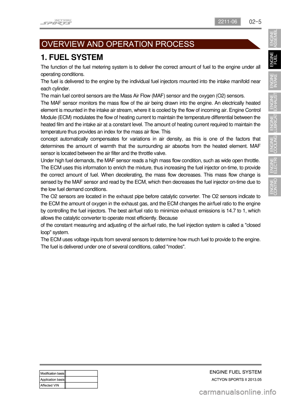
The function of the fuel metering system is to deliver the correct amount of fuel to the engine under all
operating conditions.
The fuel is delivered to the engine by the individual fuel injectors mounted into the intake manifold nea
r
each cylinder.
The main fuel control sensors are the Mass Air Flow (MAF) sensor and the oxygen (O2) sensors.
The MAF sensor monitors the mass flow of the air being drawn into the engine. An electrically heated
element is mounted in the intake air stream, where it is cooled by the flow of incoming air. Engine Control
Module (ECM) modulates the flow of heating current to maintain the temperature differential between the
heated film and the intake air at a constant level. The amount of heating current required to maintain the
temperature thus provides an index for the mass air flow. This
concept automatically compensates for variations in air density, as this is one of the factors that
determines the amount of warmth that the surrounding air absorbs from the heated element. MAF
sensor is located between the air filter and the throttle valve.
Under high fuel demands, the MAF sensor reads a high mass flow condition, such as wide open throttle.
The ECM uses this information to enrich the mixture, thus increasing the fuel injector on-time, to provide
the correct amount of fuel. When decelerating, the mass flow decreases. This mass flow change is
sensed by the MAF sensor and read by the ECM, which then decreases the fuel injector on-time due to
the low fuel demand conditions.
The O2 sensors are located in the exhaust pipe before catalytic converter. The O2 sensors indicate to
the ECM the amount of oxygen in the exhaust gas, and the ECM changes the air/fuel ratio to the engine
by controlling the fuel injectors. The best air/fuel ratio to minimize exhaust emissions is 14.7 to 1, which
allows the catalytic converter to operate most efficiently. Because
of the constant measuring and adjusting of the air/fuel ratio, the fuel injection system is called a "closed
loop" system.
The ECM uses voltage inputs from several sensors to determine how much fuel to provide to the engine.
The fuel is delivered under one of several conditions, called "modes".
Page 279 of 751

04-4
1. DESCRIPTION AND OPERATION
1) Exhaust System
When you are inspecting or replacing exhaust system components, make sure there is adequate
clearance from all points on the underbody to avoid possible
overheating of the floor panel and possible damage to the passenger compartment insulation and trim
materials.
Check the complete exhaust system and the nearby body areas and trunk lid for broken, damaged,
missing or mispositioned parts, open seams, holes, loose connections, or other deterioration which
could permit exhaust fumes to seep into the trunk may be an indication of a problem in one of these
areas. Any defects should be corrected immediately.
2) Catalytic Converter (Gasoline Engine)
When jacking or lifting the vehicle from the body side rails, be certain that the lift pads do not contact
the catalytic converter, as this could damage the catalytic converter.
Use of anything other than unleaded fuel will damage the catalyst in the catalytic converter. 1.
2.
Catalytic Converter Structure ▶
The Catalytic converter of monolith type consists of 2
walled metal bodies which is made of Cordierite. The
principal element of converter consists of the materials
like Alumina or oxidized Serume in order to apply to
Ceramic Monolith. Washer coat operates first, and
catalytic metal elements (Pt, Pd, Rh) operates to
washer coat next.
Monolith type is lighter than other types, easy to
manufacture and quickly approaches to prope
r
temperature. Washer coat is used to make a contact
surface with exhaust gas bigger by adhering closely to
small holes
of inner layer. If a lead compound or phosphorus
adheres to the surface and the temperature rises, its
surface is decreased. The total area of general
monolith converter is about 45, 000~500,000ft3. (10
times of a football field) Generally Alumina (AL2 O3) is
used as a raw materialand its 7 phases of gamma,
delta, theta have big areas and high stability for the
temperature, and nowadays gamma Alumina is used
usually.
Page 286 of 751

06-6
2. DESCRIPTION AND OPERATION
1) General Description
The cooling system maintains the engine temperature at an efficient level during all engine operating
conditions.
When the engine is cold, the cooling system cools the engine slowly or not at all. This slow cooling o
f
the engine allows the engine to warm up quickly.
The cooling system includes a radiator and recovery subsystem, cooling fans, a thermostat and
housing, a water pump, and a water pump drive belt. The timing belt drives the water pump.
All components must function properly for the cooling system to operation. The water pump draws the
coolant from the radiator. The coolant then circulates through water jackets in the engine block, the
intake manifold, and the cylinder head. When the coolant reaches the operating
temperature of the thermostat, the thermostat opens. The coolant then goes back to the radiator where
it cools.
This system directs some coolant through the hoses to the heat core. This provides for heating and
defrosting.
The coolant reservoir is connected to the radiator to recover the coolant displaced by expansion from
the high temperatures. The coolant reservoir maintains the correct coolant level.
The cooling system for this vehicle has no radiator cap or filler neck. The coolant is added to the cooling
system through the coolant reservoir.
2) Radiator
This vehicle has a lightweight tube-and-fin aluminum radiator. Plastic tanks are mounted on the upper
and the lower sides of the radiator core.
On vehicles equipped with automatic transaxles, the transaxle fluid cooler lines run through the radiato
r
tank.
A radiator drain plug is on this radiator.
To drain the cooling system, open the drain plug.
3) Coolant Reservoir
The coolant reservoir is a transparent plastic reservoir, similar to the windshield washer reservoir.
The coolant reservoir is connected to the radiator by a hose and to the engine cooling system by anothe
r
hose.
As the vehicle is driven, the engine coolant heats and expands. The portion of the engine coolant
displaced by this expansion flows from the radiator and the engine into the coolant reservoir. The ai
r
trapped in the radiator and the engine is degassed into the coolant reservoir.
When the engine stops, the engine coolant cools and contracts. The displaced engine coolant is then
drawn back into the radiator and the engine. This keeps the radiator filled with the coolant to the desired
level at all times and increases the cooling efficiency.
Maintain the coolant level between the MIN and MAX marks on the coolant reservoir when the system is
cold.
Page 411 of 751

06-4
Outside rearview mirror control bezel switch ▶
Item Rated load
Outside rearview mirror switch 12 V-2 A
ESP OFF switch 12 V-0.1 A
Mirror folding switch 12 V-0.1 A
Steering wheel heating switch 12 V-0.1 A
Rear Fog Lamp Switch 12 V-0.1 A
CTR fascia switch bezel ▶
Item Rated load
4WD control switch 12 V-0.1 A (signal load)
Driver's heated seat switch 12 V-5 A (relay load)
Passenger's heated seat switch 12 V-5 A (relay load)
Head Lamp Leveling Switch 12 V-1 A (inductive load)
Rear heated seat switch ▶
Item Rated load
Rear heated seat switch 12 V-0.1 A
Page 415 of 751

06-8
1. OVERVIEW
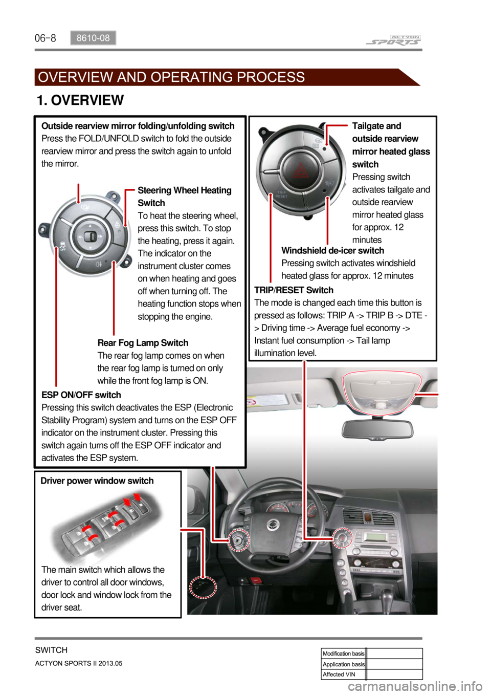
TRIP/RESET Switch
The mode is changed each time this button is
pressed as follows: TRIP A -> TRIP B -> DTE -
> Driving time -> Average fuel economy ->
Instant fuel consumption -> Tail lamp
illumination level.Windshield de-icer switch
Pressing switch activates windshield
heated glass for approx. 12 minutes
The main switch which allows the
driver to control all door windows,
door lock and window lock from the
driver seat. Tailgate and
outside rearview
mirror heated glass
switch
Pressing switch
activates tailgate and
outside rearview
mirror heated glass
for approx. 12
minutes
Driver power window switchESP ON/OFF switch
Pressing this switch deactivates the ESP (Electronic
Stability Program) system and turns on the ESP OFF
indicator on the instrument cluster. Pressing this
switch again turns off the ESP OFF indicator and
activates the ESP system. Outside rearview mirror folding/unfolding switch
Press the FOLD/UNFOLD switch to fold the outside
rearview mirror and press the switch again to unfold
the mirror.
Rear Fog Lamp Switch
The rear fog lamp comes on when
the rear fog lamp is turned on only
while the front fog lamp is ON.
Steering Wheel Heating
Switch
To heat the steering wheel,
press this switch. To stop
the heating, press it again.
The indicator on the
instrument cluster comes
on when heating and goes
off when turning off. The
heating function stops when
stopping the engine.
Page 729 of 751

03-57410-01
Rear RH seat
Fabric seat Leather seat
- 2 different heating wires according to fabric and leather specification