2013 SSANGYONG NEW ACTYON SPORTS check engine light
[x] Cancel search: check engine lightPage 60 of 751

02-290000-00
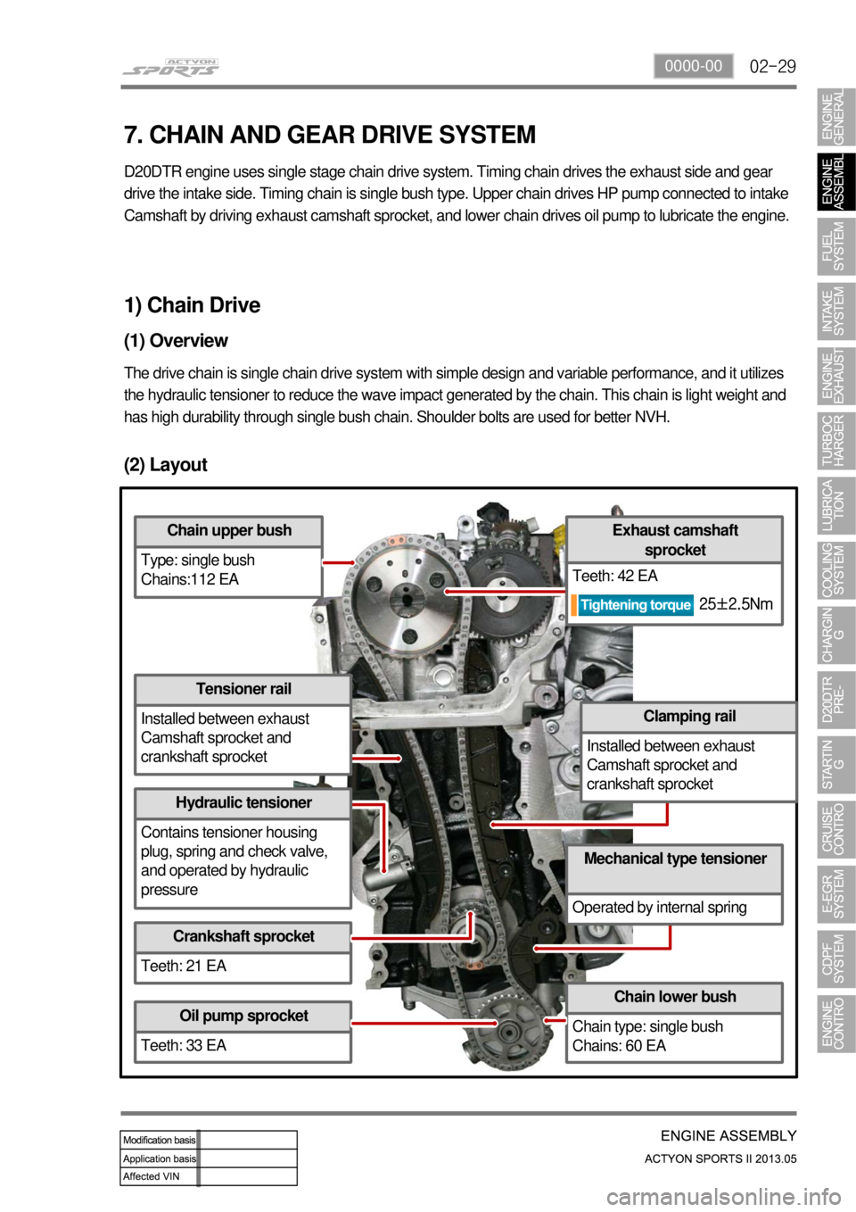
(2) Layout
Chain upper bush
Type: single bush
Chains:112 EA
Tensioner rail
Installed between exhaust
Camshaft sprocket and
crankshaft sprocket
Hydraulic tensioner
Contains tensioner housing
plug, spring and check valve,
and operated by hydraulic
pressure
Crankshaft sprocket
Teeth: 21 EA
Oil pump sprocket
Teeth: 33 EA
Chain lower bush
Chain type: single bush
Chains: 60 EA
Mechanical type tensioner
Operated by internal spring
Clamping rail
Installed between exhaust
Camshaft sprocket and
crankshaft sprocket
Exhaust camshaft sprocket
Teeth: 42 EA
1) Chain Drive
(1) Overview
The drive chain is single chain drive system with simple design and variable performance, and it utilizes
the hydraulic tensioner to reduce the wave impact generated by the chain\
. This chain is light weight and
has high durability through single bush chain. Shoulder bolts are used f\
or better NVH.
7. CHAIN AND GEAR DRIVE SYSTEM
D20DTR engine uses single stage chain drive system. Timing chain drives the exhaust side and gear
drive the intake side. Timing chain is single bush ty pe. Upper chain drives HP pump connected to intake
Camshaft by driving exhaust camshaft sprocket, and lowe r chain drives oil pump to lubricate the engine.
25±2.5Nm
Page 95 of 751

03-18
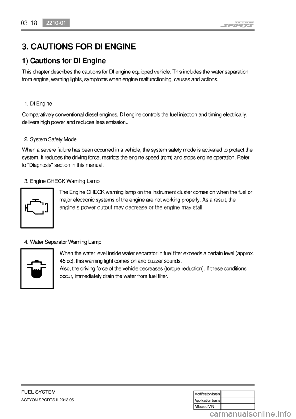
3. CAUTIONS FOR DI ENGINE
1) Cautions for DI Engine
This chapter describes the cautions for DI engine equipped vehicle. This includes the water separation
from engine, warning lights, symptoms when engine malfunctioning, causes and actions.
DI Engine 1.
Comparatively conventional diesel engines, DI engine controls the fuel injection and timing electrically,
delivers high power and reduces less emission..
System Safety Mode 2.
When a severe failure has been occurred in a vehicle, the system safety mode is activated to protect the
system. It reduces the driving force, restricts the engine speed (rpm) and stops engine operation. Refer
to "Diagnosis" section in this manual.
Engine CHECK Warning Lamp 3.
The Engine CHECK warning lamp on the instrument cluster comes on when the fuel or
major electronic systems of the engine are not working properly. As a result, the
<008c0095008e00900095008c02c5009a004700970096009e008c009900470096009c009b0097009c009b00470094008800a00047008b008c008a0099008c0088009a008c0047009600990047009b008f008c0047008c0095008e00900095008c0047009400
8800a00047009a009b0088009300930055>
Water Separator Warning Lamp 4.
When the water level inside water separator in fuel filter exceeds a certain level (approx.
45 cc), this warning light comes on and buzzer sounds.
Also, the driving force of the vehicle decreases (torque reduction). If these conditions
occur, immediately drain the water from fuel filter.
Page 258 of 751

01-91113-01
4. DIAGNOSTIC INFORMATION AND PROCEDURE
1) Oil Leak Diagnosis
Most fluid oil leaks are easily located and repaired by visually finding the leak and replacing or repairing
the necessary parts. On some occasions a fluid leak may be difficult to locate or repair. The following
procedures may help you in locating and repairing most leaks.
Finding the Leak ▶
Identify the fluid. Determine whether it is engine oil, automatic transmission fluid, power steering
fluid, etc.
Identify where the fluid is leaking from. -
-
After running the vehicle at normal operating temperature, park the vehicle over a large sheet
of paper.
Wait a few minutes.
You should be able to find the approximate location of the leak by the drippings on the paper. ·
·
·
Visually check around the suspected component.
Check around all the gasket mating surfaces for leaks. A mirror is useful for finding leaks in
areas that are hard to reach.
If the leak still cannot be found, it may be necessary to clean the suspected area with a
degreaser, steam or spray solvent. -
-
Clean the area well.
Dry the area.
Operate the vehicle for several miles at normal operating temperature and varying speeds.
After operating the vehicle, visually check the suspected component.
If you still cannot locate the leak, try using the powder or black light and dye method. ·
·
·
·
·
Clean the suspected area.
Apply an aerosol-type powder (such as foot powder) to the suspected area.
Operate the vehicle under normal operating conditoins.
Visually inspect the suspected component. You should be able to trace the leak path over the
white powder surface to the source. -
-
-
- Powder Method ▶
Page 259 of 751

01-10
Black Light and Dye Method ▶
A dye and light kit is available for finding leaks, Refer to the manufacturer's directions when using the kit.
Pour the specified amount of dye into the engine oil fill tube.
Operate the vehicle normal operating conditions as directed in the kit.
Direct the light toward the suspected area. The dyed fluid will appear as a yellow path leading to
the source. -
-
-
Once the origin of the leak has been pinpointed and traced back to its source, the cause of the leak must
be determined in order for it to be repaired properly.
If a gasket is replaced, but the sealing flange is bent, the new gasket will not repair the leak. The bent
flange must be repaired also. Before attempting to repair a leak, check for the following conditions and
correct them as they may cause a leak.Repairing the Leak ▶
Gaskets ▶
The fluid level/pressure is too high.
The crankcase ventilation system is malfunctioning.
The seal bore is damaged (scratched, burred or nicked).
The seal is damaged or worn.
Improper installation is evident.
There are cracks in the components.
The shaft surface is scratched, nicked or damaged.
A loose or worn bearing is causing excess seal wear. -
-
-
-
-
-
-
-
Page 279 of 751

04-4
1. DESCRIPTION AND OPERATION
1) Exhaust System
When you are inspecting or replacing exhaust system components, make sure there is adequate
clearance from all points on the underbody to avoid possible
overheating of the floor panel and possible damage to the passenger compartment insulation and trim
materials.
Check the complete exhaust system and the nearby body areas and trunk lid for broken, damaged,
missing or mispositioned parts, open seams, holes, loose connections, or other deterioration which
could permit exhaust fumes to seep into the trunk may be an indication of a problem in one of these
areas. Any defects should be corrected immediately.
2) Catalytic Converter (Gasoline Engine)
When jacking or lifting the vehicle from the body side rails, be certain that the lift pads do not contact
the catalytic converter, as this could damage the catalytic converter.
Use of anything other than unleaded fuel will damage the catalyst in the catalytic converter. 1.
2.
Catalytic Converter Structure ▶
The Catalytic converter of monolith type consists of 2
walled metal bodies which is made of Cordierite. The
principal element of converter consists of the materials
like Alumina or oxidized Serume in order to apply to
Ceramic Monolith. Washer coat operates first, and
catalytic metal elements (Pt, Pd, Rh) operates to
washer coat next.
Monolith type is lighter than other types, easy to
manufacture and quickly approaches to prope
r
temperature. Washer coat is used to make a contact
surface with exhaust gas bigger by adhering closely to
small holes
of inner layer. If a lead compound or phosphorus
adheres to the surface and the temperature rises, its
surface is decreased. The total area of general
monolith converter is about 45, 000~500,000ft3. (10
times of a football field) Generally Alumina (AL2 O3) is
used as a raw materialand its 7 phases of gamma,
delta, theta have big areas and high stability for the
temperature, and nowadays gamma Alumina is used
usually.
Page 388 of 751

04-58210-01
1. DESCRIPTIONS OF INDICATOR DISPLAY
Tachometer
SSPS warning light
Immobilizer indicator
Glow indicator
ESP indicator/warning light
Front fog light indicator
High beam indicator
ESP OFF indicator
Seat belt reminder (driver’s seat)
Seat belt reminder (passenger’s seat)
Engine oil pressure warning light
LCD Display
Engine overheat warning light
Engine check warning light
Auto cruise indicator
Light indicator
Winter mode indicator 1.
2.
3.
4.
5.
6.
7.
8.
9.
10.
11.
12.
13.
14.
15.
16.
17.Engine hood open warning light
Battery charge warning light
Hazard Indicator
Water separator warning light
Air bag warning light
4WD CHECK warning light
4WD LOW indicator
4WD HIGH indicator
Speedometer
Turn signal indicator
Coolant temperature gauge
Brake warning light
Door ajar warning light
ABS warning light
Fuel gauge
Low fuel level warning light 18.
19.
20.
21.
22.
23.
24.
25.
26.
27.
28.
29.
30.
31.
32.
33. It sends and receives information to/from each unit through CAN communication line. The LCD display
and separate ESP ON/OFF indicator are newly added.
Page 392 of 751

04-98210-01
Power Turning ON condition
IGN IGN ON/ CAN signal input
IGN IGN ON/ CAN signal input
IGNIGN ON/ CAN signal input
(ESP & buzzer activated)
IGN IGN ON/ CAN signal input
IGN IGN ON, CAN signal input (EBD)
IGN IGN ON/ CAN signal input
IGN Signal input
BATT When door opened
IGN Charge system fault
IGN Switch input
IGN Switch inputNo. Symbol Item
13Engine check warning
lamp
144WD LOW
indicator
15ESP indicator/ warning
light
16 ESP OFF indicator
17 Brake warning light
184WD CHECK
indicator
19Air bag warning lamp
20Door ajar waning light
21Charge warning lamp
22Seat belt warning light
(driver)
23Seat belt warning light
(passenger)
Page 403 of 751

04-20
3. WARNING LIGHTS AND INDICATORS
ESP OFF Indicator
This lamp comes on when
pressing the "ESP OFF" switch or
the ESP system is defective.
When the ESP system is
activated, this lamp blinks and a
chime sounds.
Immobilizer Indicator
This indicator comes on
when the ignition key is
communicating with the
engine control unit for
approx. 0.5 seconds.Glow Indicator
When the ignition key is turned
ON, this indicator lamp comes on
and the combustion chamber is
warmed up. In the vehicle
equipped with direct injection type
engine, this indicator may come
on very shortly or may not come
on.
Fog Lamp / Headlamp
High Beam Indicator
This lamp comes on when
the fog lamp or high beam
headlamp operates to
indicate the operating
status.Engine Oil Pressure Warning
Light
This lamp comes on if there is any
fault in the engine oil system and
goes off when a certain amount of
time has elapsed after turning ON
the ignition switch.
Door ajar warning
light
This light comes on
when a door or
tailgate is either
opened or not closed
completely.Brake warning light
This warning light comes on
and warning buzzer sounds
when the parking brake is
applied and/or the brake fluid
level is lower than specified
level.Seat belt warning lamp
The seat belt warning light comes on and
the seat belt warning chime sounds for 6
seconds when the ignition switch is
turned to "ON" position unless the
driver's seat belt is securely fastened.
This reminding operation stops when the
driver fastens the seat belt.
Engine Coolant Overheat
Warning Light
When the coolant temperature is
abnormally hot (over 120℃), this
warning light blinks and a warning
buzzer sounds at 1 Hz. (check
cooling system)
SSPS warning light
This warning light comes on when
the SSPS system is defective.
When this warning light comes
on, the steerability becomes
heavier.