Page 1234 of 1336
8810-00
Side air bag
The side air bags are installed in the
outer sides of the driver (LH) and
passenger (RH) seats to minimize
occupants' side injuries in case of a side
impact. This air bag is operated based
on the collision signal from the side
impact sensor.
Curtain air bag
The curtain air bags are installed to the upper end of
both doors. The air bag provides head protection for
the front and rear outboard occupants in a side
collision.Side impact sensor
The side impact sensors are fitted at the
bottom of both LH and RH B-pillars, and
output signals that activates the side air
bag system.
BCM (Crash signal)
The BCM activates the auto door
UNLOCK, hazard warning lamp, and
room lamps when a crash signal of the
air bag unit (SDM) is input.Seat belt pretensioner
The seat belt pretensioners of all seats are
operated at the same time, in the event of a
collision. They pull the seat belt and holds the
occupants in the seat to minimize the impact.
Page 1235 of 1336

3. AIR BAG SYSTEM OPERATING PROCESS
1) Air Bag System Input/Output
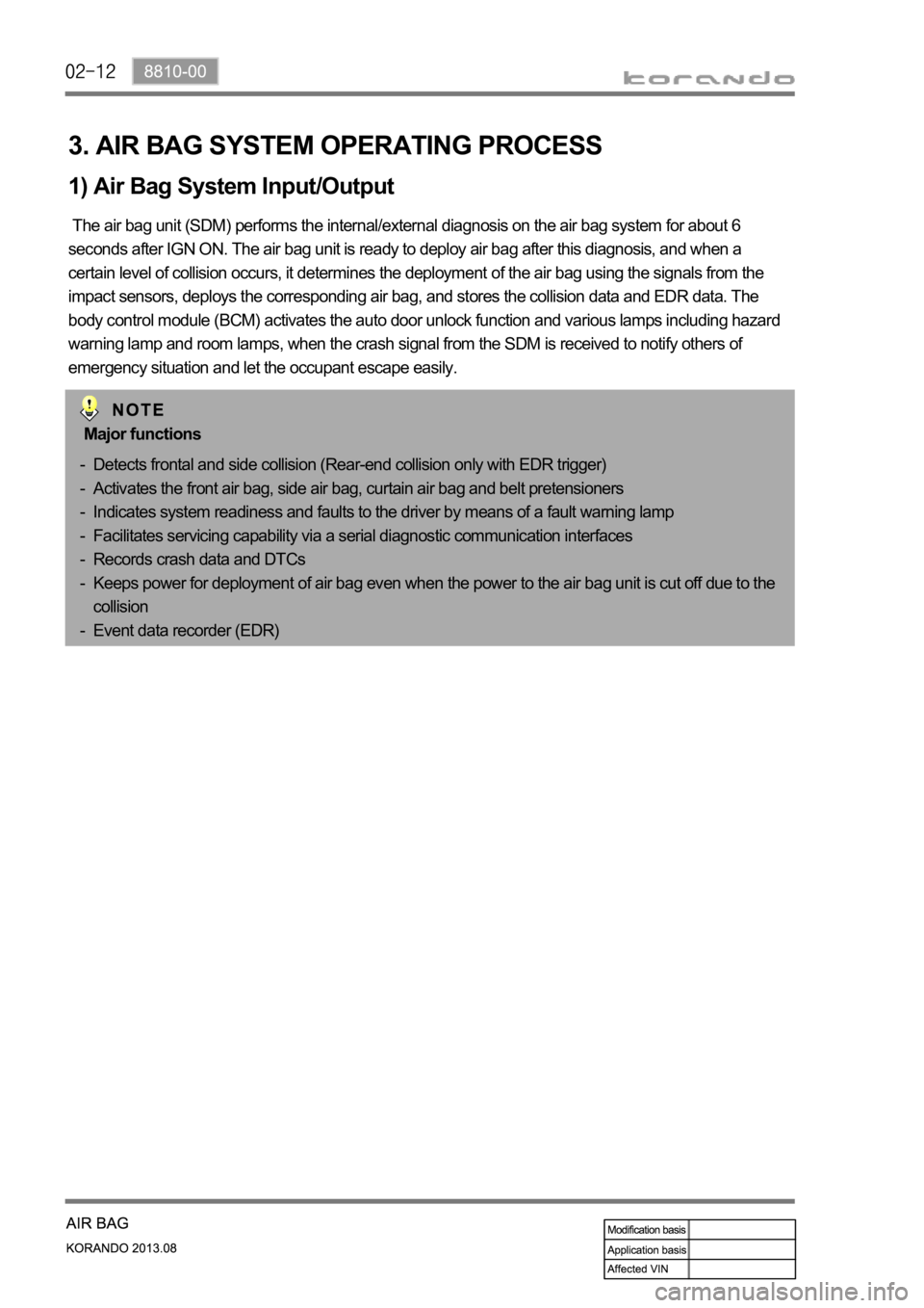
The air bag unit (SDM) performs the internal/external diagnosis on the air bag system for about 6
seconds after IGN ON. The air bag unit is ready to deploy air bag after this diagnosis, and when a
certain level of collision occurs, it determines the deployment of the air bag using the signals from the
impact sensors, deploys the corresponding air bag, and stores the collision data and EDR data. The
body control module (BCM) activates the auto door unlock function and various lamps including hazard
warning lamp and room lamps, when the crash signal from the SDM is received to notify others of
emergency situation and let the occupant escape easily.
Major functions
Detects frontal and side collision (Rear-end collision only with EDR trigger)
Activates the front air bag, side air bag, curtain air bag and belt pretensioners
Indicates system readiness and faults to the driver by means of a fault warning lamp
Facilitates servicing capability via a serial diagnostic communication interfaces
Records crash data and DTCs
Keeps power for deployment of air bag even when the power to the air bag unit is cut off due to the
collision
Event data recorder (EDR) -
-
-
-
-
-
-
Page 1242 of 1336
8810-00
4) Air Bag Deployment Signal to BCM
The air bag deployment signal from the air bag unit is sent to the BCM. This signal triggers the flash of
the hazard warning lamp to notify others of emergency situation, and is used as a signal that turns on the
room lamps and activates auto door unlock function for the occupants.
The air bag unit of a vehicle without side air bag system can also send the crash signal to the BCM
according to the value of the acceleration sensor to activate the auto door unlock and various lamps
including hazard warning lamp and room lamps.
Page 1244 of 1336

8810-00
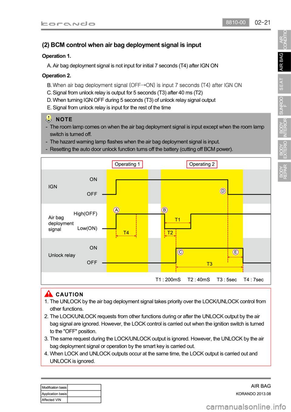
Operation 2.
Signal from unlock relay is output for 5 seconds (T3) after 40 ms (T2)
When turning IGN OFF during 5 seconds (T3) of unlock relay signal output
Signal from unlock relay is input for the rest of the time B.
C.
D.
E. Operation 1.
Air bag deployment signal is not input for initial 7 seconds (T4) after IGN ON A.
The room lamp comes on when the air bag deployment signal is input except when the room lamp
switch is turned off.
The hazard warning lamp flashes when the air bag deployment signal is input.
Resetting the auto door unlock function turns off the battery (cutting off BCM power). -
-
-
(2) BCM control when air bag deployment signal is input
The UNLOCK by the air bag deployment signal takes priority over the LOCK/UNLOCK control from
other functions.
The LOCK/UNLOCK requests from other functions during or after the UNLOCK output by the air
bag signal are ignored. However, the LOCK control is carried out when the ignition switch is turned
to the "OFF" position.
The same request during the LOCK/UNLOCK output is ignored. However, the UNLOCK by the air
bag deployment signal or operation by the smart key is carried out.
When LOCK and UNLOCK outputs occur at the same time, the LOCK output is carried out and
UNLOCK is ignored. 1.
2.
3.
4.
Page 1271 of 1336
Head restraint adjustment (Height)
3) Rear Seat
(1) Rear seat operation
The rear seat is a 6:4 split seat and a manual seat that the angle of the head restraint and seatback of the
seat can be adjusted. And the heated wires in the rear seat cushion and seatback can be operated with
rear seat heated wire switches located on the LH/RH rear door trim.
The head restraint can be raised
without pressing the head
restraint sleeve (A) or lowered
with the sleeve (A) pressed.
Seatback reclining adjustment
To adjust the seatback angle,
pull the lock release lever on the
upper part of the seat to release
the lock.