Page 992 of 1336
6. REAR SUSPENSION COMPONENT LAYOUT
Multi-link type suspension is the independent suspension. It provides good ride comfort and drivability
by reducing the coil spring weight. Also, it increases the space for passenger compartment by lowering
the floor.
This type of suspension consists of multiple links such as trailing arm, upper arm, lower arm and track
rod.
Shock absorber assembly
This vehicle uses the gas
shock absorber. This
relieves the vertical
vibrations of vehicle to
provide ride comforts,
prevents the spring break,
enhances drivability, and
extends the life span of
steering components.
Upper arm assembly
Upper arm is installed between knuckle and sub
frame and controls the lateral load and vehicle
height.
Trailing arm assembly
Trailing arm is installed between knuckle and
vehicle body and controls the front and rear load.
Track rod assembly
Track rod is installed between knuckle and rear
sub frame and controls and compensates the
lateral load.
Page 1003 of 1336

3680-01
1. GENERAL INFORMATION
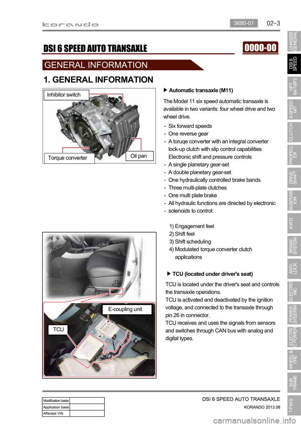
Automatic transaxle (M11)
The Model 11 six speed automatic transaxle is
available in two variants: four wheel drive and two
wheel drive.
Six forward speeds
One reverse gear
A toruqe converter with an integral converter
lock-up clutch with slip control capabilities
Electronic shift and pressure controls
A single planetary gear-set
A double planetary gear-set
One hydraulically controlled brake bands
Three multi-plate clutches
One multi plate brake
All hydraulic functions are directed by electronic
solenoids to control: -
-
-
-
-
-
-
-
-
-
Engagement feel
Shift feel
Shift scheduling
Modulated torque converter clutch
applications 1)
2)
3)
4) Inhibitor switch
Oil pan
Torque converter
TCU (located under driver's seat)
TCU is located under the driver's seat and controls
the transaxle operations.
TCU is activated and deactivated by the ignition
voltage, and connected to the transaxle through
pin 26 in connector.
TCU receives and uses the signals from sensors
and switches through CAN bus with analog and
digital types.
E-coupling unit
TCU
Page 1007 of 1336

3680-01
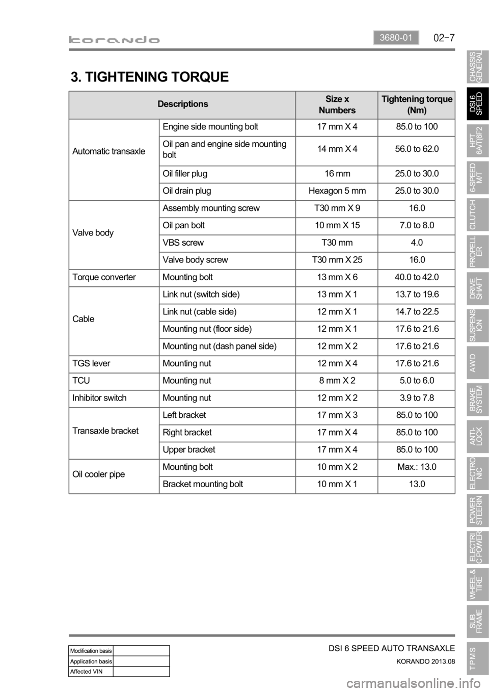
3. TIGHTENING TORQUE
DescriptionsSize x
NumbersTightening torque
(Nm)
Automatic transaxleEngine side mounting bolt 17 mm X 4 85.0 to 100
Oil pan and engine side mounting
bolt14 mm X 4 56.0 to 62.0
Oil filler plug 16 mm 25.0 to 30.0
Oil drain plug Hexagon 5 mm 25.0 to 30.0
Valve bodyAssembly mounting screw T30 mm X 9 16.0
Oil pan bolt 10 mm X 15 7.0 to 8.0
VBS screw T30 mm 4.0
Valve body screw T30 mm X 25 16.0
Torque converter Mounting bolt 13 mm X 6 40.0 to 42.0
CableLink nut (switch side) 13 mm X 1 13.7 to 19.6
Link nut (cable side) 12 mm X 1 14.7 to 22.5
Mounting nut (floor side) 12 mm X 1 17.6 to 21.6
Mounting nut (dash panel side) 12 mm X 2 17.6 to 21.6
TGS lever Mounting nut 12 mm X 4 17.6 to 21.6
TCU Mounting nut 8 mm X 2 5.0 to 6.0
Inhibitor switch Mounting nut 12 mm X 2 3.9 to 7.8
Transaxle bracketLeft bracket 17 mm X 3 85.0 to 100
Right bracket 17 mm X 4 85.0 to 100
Upper bracket 17 mm X 4 85.0 to 100
Oil cooler pipeMounting bolt 10 mm X 2 Max.: 13.0
Bracket mounting bolt 10 mm X 1 13.0
Page 1030 of 1336
2. GENERAL INFORMATION
Automatic transaxle (6F24)
The Model 6F24 six speed automatic transaxle is
available in two variants: four wheel drive and two
wheel drive.
Six forward speeds
One reverse gear
A toruqe converter with an integral converter lock-
up clutch with slip control capabilities
Planetary gear-set (3EA)
Clutches (2EA)
Brake (3EA)
O.W.C (1EA)
All hydraulic functions are directed by electronic
solenoids to control: -
-
-
-
-
-
-
-
Engagement feel
Shift feel
Shift scheduling
Modulated torque converter clutch
applications 1)
2)
3)
4) Inhibitor switch
Oil pan
Torque converter
TCU (located under driver's seat)
TCU is located under the driver's seat and controls
the transaxle operations.
TCU receives and uses the signals from sensors
and switches through CAN bus with analog and
digital types.
E-coupling unit
TCU
Page 1034 of 1336

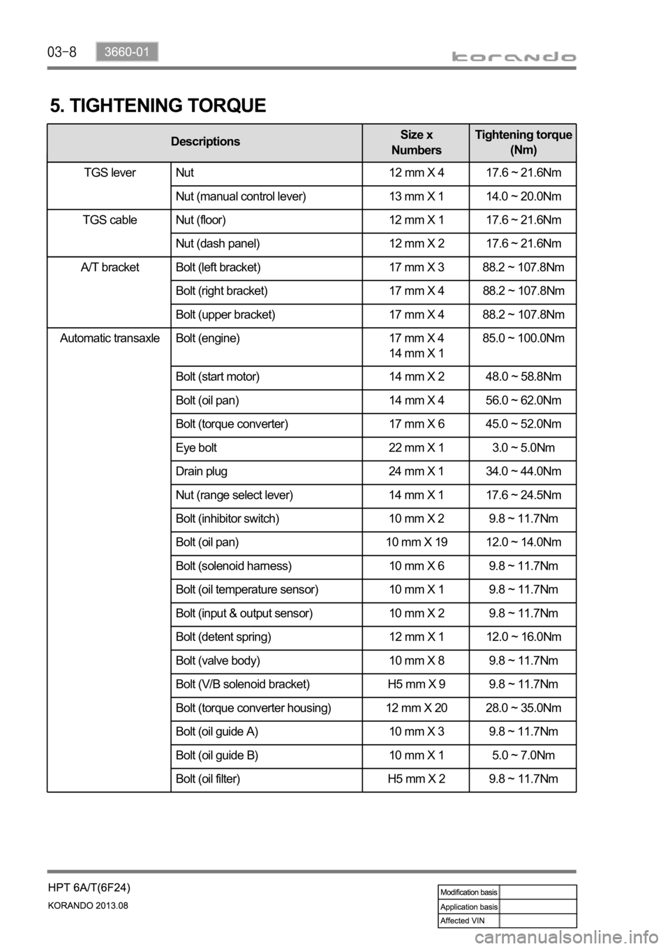
Automatic transaxle Bolt (engine) 17 mm X 4
14 mm X 1 85.0 ~ 100.0Nm
Bolt (start motor) 14 mm X 2 48.0 ~ 58.8Nm
Bolt (oil pan) 14 mm X 4 56.0 ~ 62.0Nm
Bolt (torque converter) 17 mm X 6 45.0 ~ 52.0Nm
Eye bolt 22 mm X 1 3.0 ~ 5.0Nm
Drain plug 24 mm X 1 34.0 ~ 44.0Nm
Nut (range select lever) 14 mm X 1 17.6 ~ 24.5Nm
Bolt (inhibitor switch) 10 mm X 2 9.8 ~ 11.7Nm
Bolt (oil pan) 10 mm X 19 12.0 ~ 14.0Nm
Bolt (solenoid harness) 10 mm X 6 9.8 ~ 11.7Nm
Bolt (oil temperature sensor) 10 mm X 1 9.8 ~ 11.7Nm
Bolt (input & output sensor) 10 mm X 2 9.8 ~ 11.7Nm
Bolt (detent spring) 12 mm X 1 12.0 ~ 16.0Nm
Bolt (valve body) 10 mm X 8 9.8 ~ 11.7Nm
Bolt (V/B solenoid bracket) H5 mm X 9 9.8 ~ 11.7Nm
Bolt (torque converter housing) 12 mm X 20 28.0 ~ 35.0Nm
Bolt (oil guide A) 10 mm X 3 9.8 ~ 11.7Nm
Bolt (oil guide B) 10 mm X 1 5.0 ~ 7.0Nm
Bolt (oil filter) H5 mm X 2 9.8 ~ 11.7Nm
5. TIGHTENING TORQUE
DescriptionsSize x
NumbersTightening torque
(Nm)
TGS lever Nut 12 mm X 4 17.6 ~ 21.6Nm
Nut (manual control lever) 13 mm X 1 14.0 ~ 20.0Nm
Nut (floor) 12 mm X 1 17.6 ~ 21.6Nm
Nut (dash panel) 12 mm X 2 17.6 ~ 21.6Nm
A/T bracket Bolt (left bracket) 17 mm X 3 88.2 ~ 107.8Nm
Bolt (right bracket) 17 mm X 4 88.2 ~ 107.8Nm
Bolt (upper bracket) 17 mm X 4 88.2 ~ 107.8Nm
TGS lever
TGS cable
Page 1091 of 1336
2. SPECIFICATION (DSL ONLY)
Unit Description Specification
Front brake Type Ventilated disc
Outer diameter of disc
Inner diameter of caliper cylinder
Thickness of disc 26 mm (wear limit: 24 mm)
Thickness of brake pad 10.5 mm (wear limit: 2 mm)
Pad wear indicator Mechanical type
Rear brake Type Solid disc
Outer diameter of disc
Thickness of disc 10 mm (wear limit: 8.4 mm)
Thickness of brake pad 10 mm (wear limit: 2 mm)
Pad wear indicator Mechanical type
Brake booster Type Vacuum assist type
Size
Master cylinder Type Tandem (level sensor installed)
Inner diameter of cylinder
Brake pedal Maximum operating stroke
Pedal ratio 3.8 : 1
Free play 3 to 10 mm
Parking brake Type Mechanically expanded rear lining
Operating type Hand operated type
Inner diameter of drum
Brake oil Specification DOT 4
Capacity 0.7 to 0.8 liters
Service interval for brake fluid: Change every other year.
Page 1123 of 1336
3. ESP OFF switch
Located on the left side of
instrument panel.2. Steering wheel angle
sensor
Located on column shaft with
contact coil.1. HECU assembly
Located under the power
steering fluid reservoir and
contains the pressure sensor.
2. COMPONENTS
4. Sensor cluster
Located on the floor under front
passenger seat.5. Wheel speed sensor
(4WD/2WD-front)
Located on knuckle. the
appearance of front sensor is
same with rear sensor.6. Rear wheel speed sensor
(2WD)
Located on knuckle. The
appearance is different from
that for 4WD.
Page:
< prev 1-8 9-16 17-24