Page 1102 of 1336
3. G-sensor (for 4WD)
Located on the floor under
parking brake bracket in center
console.4. Rear wheel speed sensor
(for 2WD)
Located on knuckle. The
appearance is different from that
for 4WD.4. Wheel speed sensor
(for 4WD)
Located on knuckle. The
appearance of front sensor is
same with rear sensor.
2. ABS warning lamp
EBD warning lamp (ABS warning lamp +
Brake warning lamp)1. ABS hydraulic device and control unit
Located under the power steering fluid reservoir and
contains the pressure sensor.
2. COMPONENT
Page 1103 of 1336
4890-00
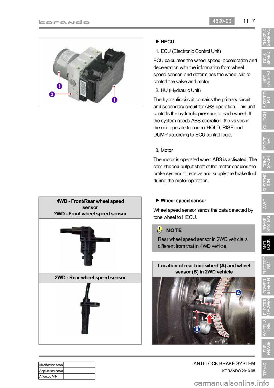
4WD - Front/Rear wheel speed
sensor
2WD - Front wheel speed sensor
2WD - Rear wheel speed sensor
ECU (Electronic Control Unit) 1.
ECU calculates the wheel speed, acceleration and
deceleration with the information from wheel
speed sensor, and determines the wheel slip to
control the valve and motor.
HU (Hydraulic Unit) 2.
The hydraulic circuit contains the primary circuit
and secondary circuit for ABS operation. This unit
controls the hydraulic pressure to each wheel. If
the system needs ABS operation, the valves in
the unit operate to control HOLD, RISE and
DUMP according to ECU control logic.
Motor 3.
The motor is operated when ABS is activated. The
cam-shaped output shaft of the motor enables the
brake system to receive and supply the brake fluid
during the motor operation.
Wheel speed sensor
Wheel speed sensor sends the data detected by
tone wheel to HECU.
HECU
Rear wheel speed sensor in 2WD vehicle is
different from that in 4WD vehicle.
Location of rear tone wheel (A) and wheel
sensor (B) in 2WD vehicle
Page 1105 of 1336
4890-00
3. ABS CONTROL LOGIC
The principal ABS control logic is the determination of the reference speed by choosing one wheel
meeting a certain condition, while sensing the speed information from 4 wheel speed sensors when the
vehicle is being driven.
For example, when the comparison of the reference speed with front right wheel speed shows a slip, the
control signal is determined according to whether it's deceleration or acceleration. If the control
conditions are met, the brake for the front right wheel will be got under control.
Page 1107 of 1336
4890-00
2) EBD (Electronic Brake-force Distribution) Warning Lamp (Brake
Warning Lamp)
EBD warning lamp when the system performs the self diagnosis and when it detects the malfunction of
EBD system. However, the brake warning lamp comes on regardless of EBD when the parking brake is
applied.
EBD warning lamp ON:
When turning the ignition switch to ON position, ABS warning lamp and the brake warning lamp
comes on for 3 seconds for self diagnosis and goes off if the system is OK (initialization mode).
When applying the parking brake, the brake warning lamp comes on.
When the brake fluid is not sufficient, the brake warning lamp comes on.
When the self-diagnosis is performing, the warning lamp comes on.
When the HECU connector is disconnected, the warning lamp comes on.
When the system is defective, ABS warning lamp and the brake warning lamp come on
simultaneously. 1.
2.
3.
4.
5.
6.
When the solenoid valve is defective
When one or more wheel sensors are defective
When ABS HECU is defective
When the voltage is abnormal
When valve relay is defective a.
b.
c.
d.
e.
When the communication between warning lamp CAN module in meter cluster, the warning lamp
comes on. 7.
Page 1112 of 1336
3) Basic ABS Control
Operation of ABS control unit
Applications of the ABS control unit The signals
produced by the wheel sensors are evaluated in
the electronic control unit. From the information
received, the control unit must first compute the
following variables:
Wheel speed
Reference speed
Deceleration
Slip -
-
-
-
Reference speed
The reference speed is the mean, I.e. average speed of all wheel speeds determined by simple
approximation.
Simplified ABS control
If, during braking, one wheel speed deviates from the reference speed, the ABS control unit attempts to
correct that wheel speed by modulating the brake pressure until it again matches the reference speed.
When all four wheels tend to lock, all four wheels speeds suddenly deviate from the previously
determined reference speed. In that case, the control cycle is initiated again in order to again correct the
wheel speed by modulating the brake pressure.
Page 1114 of 1336
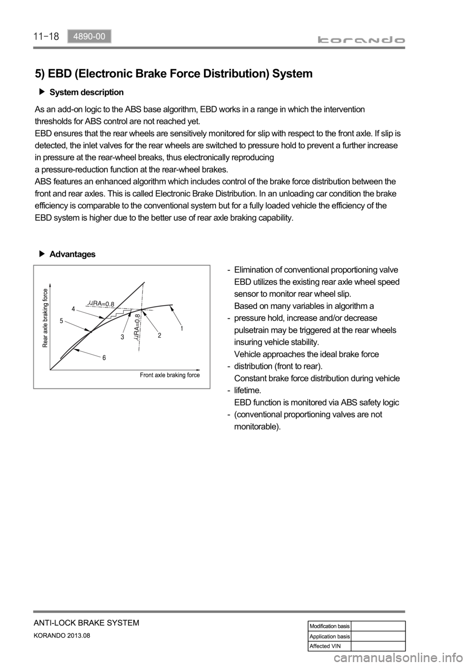
5) EBD (Electronic Brake Force Distribution) System
System description
As an add-on logic to the ABS base algorithm, EBD works in a range in which the intervention
thresholds for ABS control are not reached yet.
EBD ensures that the rear wheels are sensitively monitored for slip with respect to the front axle. If slip is
detected, the inlet valves for the rear wheels are switched to pressure hold to prevent a further increase
in pressure at the rear-wheel breaks, thus electronically reproducing
a pressure-reduction function at the rear-wheel brakes.
ABS features an enhanced algorithm which includes control of the brake force distribution between the
front and rear axles. This is called Electronic Brake Distribution. In an unloading car condition the brake
efficiency is comparable to the conventional system but for a fully loaded vehicle the efficiency of the
EBD system is higher due to the better use of rear axle braking capability.
Advantages
Elimination of conventional proportioning valve
EBD utilizes the existing rear axle wheel speed
sensor to monitor rear wheel slip.
Based on many variables in algorithm a
pressure hold, increase and/or decrease
pulsetrain may be triggered at the rear wheels
insuring vehicle stability.
Vehicle approaches the ideal brake force
distribution (front to rear).
Constant brake force distribution during vehicle
lifetime.
EBD function is monitored via ABS safety logic
(conventional proportioning valves are not
monitorable). -
-
-
-
-
Page 1126 of 1336
0000-00
2) EBD (Electronic Brake-force Distribution) Warning Lamp (Brake
Warning Lamp)
EBD warning lamp when the system perform the self diagnosis and when it detects the malfunction of
EBD system. However, the brake warning lamp comes on regardless of EBD when the parking brake is
applied.
EBD warning lamp ON:
When turning the ignition switch to ON position, ABS warning lamp and the brake warning lamp
comes on for 3 seconds for self diagnosis and goes off if the system is OK (initialization mode).
When applying the parking brake, the brake warning lamp comes on.
When the brake fluid is not sufficient, the brake warning lamp comes on.
When the self-diagnosis is performing, the warning lamp comes on.
When the HECU connector is disconnected, the warning lamp comes on.
When the system is defective, ABS warning lamp and the brake warning lamp come on
simultaneously. 1.
2.
3.
4.
5.
6.
When the solenoid valve is defective
When one or more wheel sensors are defective
When ABS HECU is defective
When the voltage is abnormal
When valve relay is defective a.
b.
c.
d.
e.
When the communication between warning lamp CAN module in meter cluster, the warning lamp
comes on. 7.
3) ESP OFF Indicator
ESP OFF indicator ON:
When turning the ignition switch to ON position, ESP warning lamp comes on for 3 seconds for self
diagnosis and goes off if the system is OK (initialization mode).
When the ESP OFF switch is pressed to turn off ESP function, ESP OFF indicator comes on. 1.
2.
4) ESP Warning Lamp
ESP warning lamp ON:
When turning the ignition switch to ON position, ESP warning lamp comes on for 3 seconds for self
diagnosis and goes off if the system is OK (initialization mode).
When the system is defective, the warning lamp comes on.
When the ESP function is activated, ESP warning lamp blinks with the interval of 2 Hz.
When the communication between warning lamp CAN module in meter cluster, the warning lamp
comes on. 1.
2.
3.
4.
5.
5) ESP OFF Switch
If ESP OFF switch is pressed, ESP function is deactivated and the ESP OFF indicator in the instrument
cluster comes on.
To resume the ESP function, press the switch again. At this time, ESP OFF indicator goes out.
Page 1131 of 1336
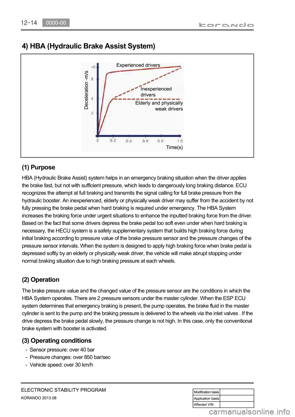
4) HBA (Hydraulic Brake Assist System)
(1) Purpose
HBA (Hydraulic Brake Assist) system helps in an emergency braking situation when the driver applies
the brake fast, but not with sufficient pressure, which leads to dangerously long braking distance. ECU
recognizes the attempt at full braking and transmits the signal calling for full brake pressure from the
hydraulic booster. An inexperienced, elderly or physically weak driver may suffer from the accident by not
fully pressing the brake pedal when hard braking is required under emergency. The HBA System
increases the braking force under urgent situations to enhance the inputted braking force from the driver.
Based on the fact that some drivers depress the brake pedal too soft even under when hard braking is
necessary, the HECU system is a safety supplementary system that builds high braking force during
initial braking according to pressure value of the brake pressure sensor and the pressure changes of the
pressure sensor intervals. When the system is designed to apply high braking force when brake pedal is
depressed softly by an elderly or physically weak driver, the vehicle will make abrupt stopping under
normal braking situation due to high braking pressure at each wheels.
(2) Operation
The brake pressure value and the changed value of the pressure sensor are the conditions in which the
HBA System operates. There are 2 pressure sensors under the master cylinder. When the ESP ECU
system determines that emergency braking is present, the pump operates, the brake fluid in the master
cylinder is sent to the pump and the braking pressure is delivered to the wheels via the inlet valves . If the
drive depress the brake pedal slowly, the pressure change is not high. In this case, only the conventional
brake system with booster is activated.
(3) Operating conditions
Sensor pressure: over 40 bar
Pressure changes: over 850 bar/sec
Vehicle speed: over 30 km/h -
-
-