Page 826 of 1336
8) Buzzer
Specifications
Function Signal
Part name PKM17EPP-2002-B0 (MURATA, Piezoelectric Sound Components)
Permitted input voltage 25 VP-P or less
Operating temperature
Storage temperature
Sound pressure level 70 dB/min (3 Vp-p, 2 kHz, square wave, 10 cm)
Capacitance
Priority of instrument cluster buzzer output
If there are multiple signals at a time, the operation should be completed by the priority.
Priority
ItemBuzzer output
time
Operating condition
ON OFF
1 PAS See PAS
2 ESP 0.1sec 0.1secInstrument cluster buzzer output signal is
received from ABS/ESP
3Engine overheat
warning lamp0.5sec 0.5sec
4Water separator
warning light0.5sec 0.5secWater separator warning light ON with
IGN ON
5 Parking brake 2.8sec 1.5secParking brake applied depending on
vehicle speed
Page 833 of 1336

8010-01
Pin No. Message Operating condition
Domestic Export
Tire alignment
(applies to
vehicle with
EPS)
CAN scan(This message goes off when all the CAN signal inputs
are normal)
ESCLLCD display shows this message when ESCL (Electric
Steering Column Lock) system is defective. There is
no specific ESCL warning light on the instrument
cluster.
This problem could be temporary. Turn the ignition off
and then on again to check if this message will be
disappeared.
This message helps the driver to predict the driving
direction since the tire alignment is displayed on the
instrument cluster.
The images on the left show that the tires are
aligned to the left. When the tires are aligned to the
right, the image is symmetrical vertically.
Tire alignment is displayed between level 0 and
level 5 depending on the alignment degree when
the ignition switch is turned to "ON" position from
"OFF" position with the shift lever in "P" or "N"
position. While the images up to level 2 comes on
for 5 seconds, the images from level 3 stay on.
These messages are not displayed when the EPS
check message is displayed. -
-
-
-
Pin No. Message Operating condition
Page 836 of 1336
8510-00
1. SPECIFICATIONS
Unit Specification
Multifunction
switchRated voltage DC 12 V
Rated
loadMultifunction
turn light
switchLight switch ON: 1 A (relay load)
Dimmer & passing
switchHigh beam: 0.3 A (relay load)
Low beam: 0.3 A (relay load)
Passing: 0.3 A (relay load)
Turn signal lamp
switch0.1 A (relay load)
AUTO hazard
warning flasher
switch0.1 A (relay load)
Multifunction
wiper
switchWiper switchLO: 0.1 A (relay load)
HI: 0.1 A (relay load)
Fixed: Max. 0.1 A (relay load)
AUTO washer switch
0.1 A (relay load)
Washer switch 0.1 A (relay load)
Wiping speed control
switchMax. 25 mA
Mist switch 0.1 A (relay load)
Rear wiper & washer
switchRear wiper: 0.1 A (relay load)
Multifunction switch
Page 872 of 1336
8510-00
Multifunction wiper switches
2) Multifunction Switch
Multifunction light switches
Light switch
Front wiper switch
Wiper speed dial
Rear wiper switch Front fog lamp switch
Front auto washer switch The multifunction switch contains the auto washer and wiper switch, front fog lamp switch and auto
hazard warning flasher switch. For the vehicle with air bag, since the contact coil is fitted to the upper part
of the multifunction switch and ESP steering wheel angle sensor is fitted to upper part of the contact coil,
pay attention to when removing and fitting or checking the wiring.
Page 994 of 1336
A. Indicators on instrument cluster
C. HECU assembly
The HECU assemblies for ABS and ESP have
similar appearance but they have different inner
structure and connector connections from each
other. D. Front brake assembly
The disc brake for 4WD vehicle is the same with
the one for 2WD vehicle.
7. BRAKE SYSTEM AND ESP SYSTEM LAYOUT
B. Master cylinder assembly
Description for master cylinder in this chapter is
based on ABS/ESP equipped vehicle. For CBS,
there is an extra pressure valve mounted to the
master cylinder.
CaliperDisc
Parking brake
warning light
ABS warning lamp
ESP indicator
Page 1015 of 1336
3680-01
This information is used by the TCU to decide which shift pattern to select and for shift energy
management. Electro-hydraulic solenoid valves and variable bleed solenoids control the transaxle gear
changes.
Six variable bleed solenoids and four on/off solenoids are used to direct transaxle fluid flow to control the
fluid pressure within the three clutches and two bands. Separate pressure regulators are used
exclusively for torque converter clutch control and main transaxle line pressure.
The TCU monitors all TCU inputs and outputs to confirm correct system operation. If a fault occurs the
TCU is able to perform default action and inform the driver of the problem through the instrument cluster
warning lights. Detailed information is available via trouble codes which can be read with the service tool.
Page 1043 of 1336

3660-01
5. TRANSAXLE ELECTRONIC CONTROL SYSTEM
1) General Information
The transmission control unit (TCU) and its input/output network control the following transmission
operations:
Shift timing
Line pressure
Clutch pressure (shift feel)
Torque converter clutch -
-
-
-
also uses these signals when determining transaxle operating strategy. Using all of these input signals,
the TCU can determine when the time and conditions are right for a shift, or when to apply or release the
torque converter clutch. It will also determine the pressure needed to optimise shift feel.
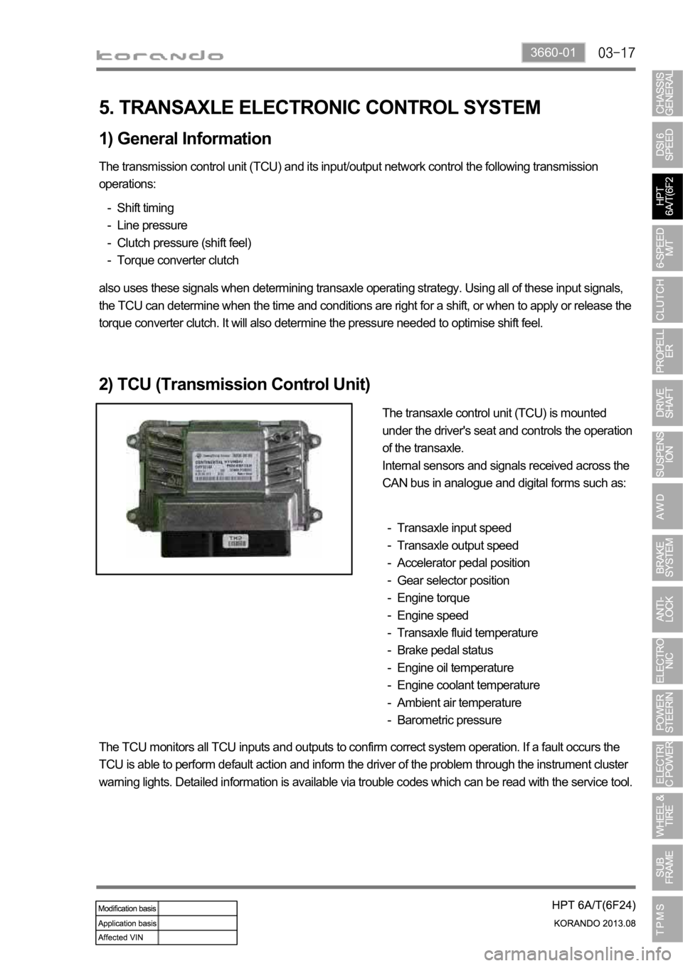
2) TCU (Transmission Control Unit)
The transaxle control unit (TCU) is mounted
under the driver's seat and controls the operation
of the transaxle.
Internal sensors and signals received across the
CAN bus in analogue and digital forms such as:
Transaxle input speed
Transaxle output speed
Accelerator pedal position
Gear selector position
Engine torque
Engine speed
Transaxle fluid temperature
Brake pedal status
Engine oil temperature
Engine coolant temperature
Ambient air temperature
Barometric pressure -
-
-
-
-
-
-
-
-
-
-
-
The TCU monitors all TCU inputs and outputs to confirm correct system operation. If a fault occurs the
TCU is able to perform default action and inform the driver of the problem through the instrument cluster
warning lights. Detailed information is available via trouble codes which can be read with the service tool.