Page 1008 of 1336

1. OVERVIEW
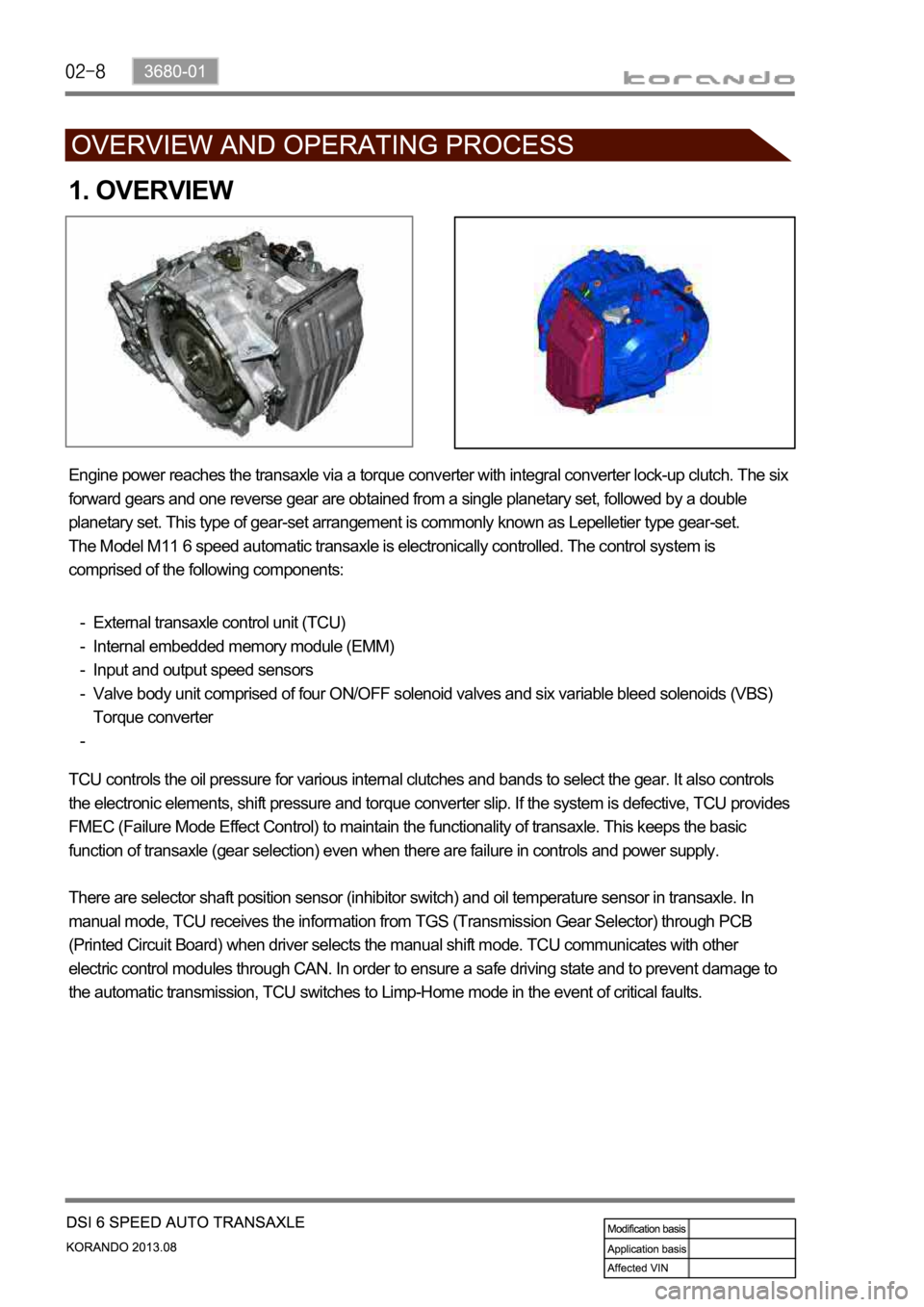
Engine power reaches the transaxle via a torque converter with integral converter lock-up clutch. The six
forward gears and one reverse gear are obtained from a single planetary set, followed by a double
planetary set. This type of gear-set arrangement is commonly known as Lepelletier type gear-set.
The Model M11 6 speed automatic transaxle is electronically controlled. The control system is
comprised of the following components:
External transaxle control unit (TCU)
Internal embedded memory module (EMM)
Input and output speed sensors
Valve body unit comprised of four ON/OFF solenoid valves and six variable bleed solenoids (VBS)
Torque converter -
-
-
-
-
TCU controls the oil pressure for various internal clutches and bands to select the gear. It also controls
the electronic elements, shift pressure and torque converter slip. If the system is defective, TCU provides
FMEC (Failure Mode Effect Control) to maintain the functionality of transaxle. This keeps the basic
function of transaxle (gear selection) even when there are failure in controls and power supply.
There are selector shaft position sensor (inhibitor switch) and oil temperature sensor in transaxle. In
manual mode, TCU receives the information from TGS (Transmission Gear Selector) through PCB
(Printed Circuit Board) when driver selects the manual shift mode. TCU communicates with other
electric control modules through CAN. In order to ensure a safe driving state and to prevent damage to
the automatic transmission, TCU switches to Limp-Home mode in the event of critical faults.
Page 1016 of 1336

3) Shift Map Selection
The driver can manually select between normal (S) and winter modes (W) via the mode switch.
Depending on the transaxle temperature, uphill and downhill grades and altitude, shift maps will be
selected by the TCU to suit the driving conditions. The following maps are available.
Standard (Normal) Mode
Normal Mode is selected when the lever is in the D position with the mode switch in the normal (S)
position and the transaxle is within normal temperature ranges. Shift schedule points are optimised for
fuel efficiency and general driving conditions.
Uphill and Downhill Mode
In this mode, depending on the load of the vehicle, adaptive shift maps are selected to progressively
adjust the shift points and torque converter lock points.
Altitude Mode
Shift points are automatically adjusted at higher altitudes to compensate for changes in engine torque
where the torque produced by the engine is greatly reduced by the effects of reduced barometric
pressure and temperature.
Winter (W) Mode
When winter mode is selected, starting in second gear is facilitated and the WINTER mode indicator
light is switched ON. To prevent wheel spin on slippery surfaces, the transmission will not allow first gear
unless manually overridden.
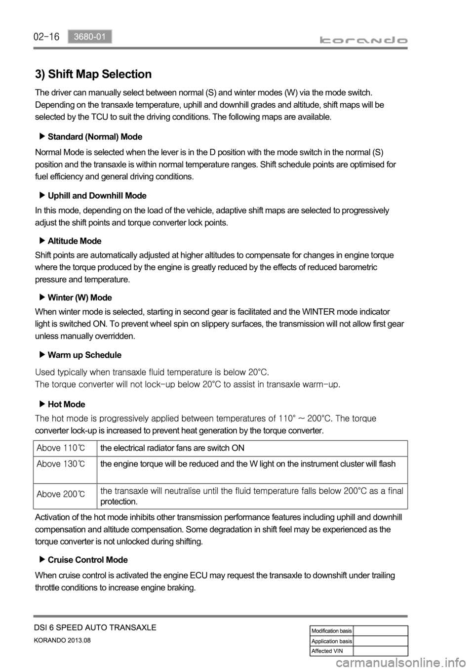
Warm up Schedule
Hot Mode
converter lock-up is increased to prevent heat generation by the torque converter.
Activation of the hot mode inhibits other transmission performance features including uphill and downhill
compensation and altitude compensation. Some degradation in shift feel may be experienced as the
torque converter is not unlocked during shifting.
Cruise Control Mode
When cruise control is activated the engine ECU may request the transaxle to downshift under trailing
throttle conditions to increase engine braking.
the electrical radiator fans are switch ON
the engine torque will be reduced and the W light on the instrument cluster will flash
protection.
Page 1037 of 1336

3660-01
1. OVERVIEW
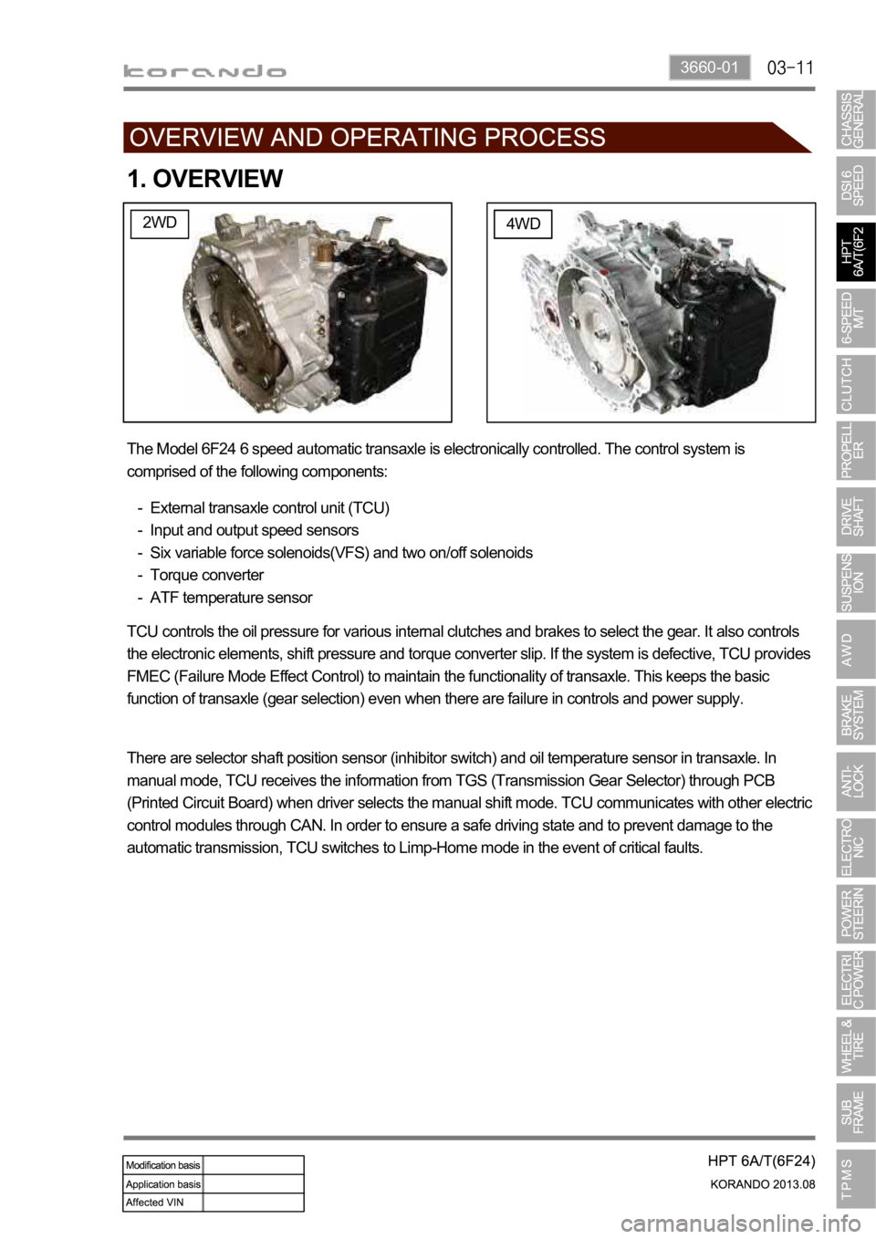
2WD4WD
The Model 6F24 6 speed automatic transaxle is electronically controlled. The control system is
comprised of the following components:
External transaxle control unit (TCU)
Input and output speed sensors
Six variable force solenoids(VFS) and two on/off solenoids
Torque converter
ATF temperature sensor -
-
-
-
-
TCU controls the oil pressure for various internal clutches and brakes to select the gear. It also controls
the electronic elements, shift pressure and torque converter slip. If the system is defective, TCU provides
FMEC (Failure Mode Effect Control) to maintain the functionality of transaxle. This keeps the basic
function of transaxle (gear selection) even when there are failure in controls and power supply.
There are selector shaft position sensor (inhibitor switch) and oil temperature sensor in transaxle. In
manual mode, TCU receives the information from TGS (Transmission Gear Selector) through PCB
(Printed Circuit Board) when driver selects the manual shift mode. TCU communicates with other electric
control modules through CAN. In order to ensure a safe driving state and to prevent damage to the
automatic transmission, TCU switches to Limp-Home mode in the event of critical faults.
Page 1057 of 1336
Front view Rear view
1. OVERVIEW
This vehicle is equipped with WM6F1 M/T (Manual Transmission). This transmission is integrated with an
axle and designed to maximize the driving performance by optimizing the gear ratio according to the
engine torque.
WM6F1 M/T assembly
Page 1168 of 1336
The front sub frame consists of 4 body bush mountings(A) and 2 engine bush mountings(B) which
reduce the vibration from the powertrain and road, and also control the torque. And the two engine bush
mountings consist of an engine mounting which supports the engine powertrain and a transmission
mounting.
The engine side and transmission side mountings are rubber mountings with brackets and insulators
while the body mounting is a rubber bush mounting which is fitted to the frame.
Installation of front sub
frame (4WD)The installation of the front sub frame is the same for both automatic
transmission and manual transmission. For 4WD, the PTU and the
propeller shaft are installed.
Installation of front sub
frame (2WD)The installation of the front sub frame is the same for both automatic
transmission and manual transmission.
PTU assembly
Page 1169 of 1336
4015-01
Installation of rear sub
frame (4WD)The installation of the rear sub frame is the same for both automatic
transmission and manual transmission. For 4WD, the E-coupling, propeller
shaft and rear axle are installed.
Installation of rear sub
frame (2WD) The installation of the rear sub frame is the same for both automatic
transmission and manual transmission.
The rear sub frame system consists of body bush mountings and direct mountings which reduce the
vibration transmitted from the powertrain and road to the vehicle body.
For 4WD, it consists of 4 body mountings (bush mountings) and 2 axle mountings (bush mountings) and
for 2WD, it consists of 4 body mountings (direct mountings).