Page 1162 of 1336

If weight is not equally distributed around the wheel, unbalance centrifugal force by the wheel rotation
produces vibration. As the centrifugal force is produced proportional to the square of the rotating speed,
the wheel weight should be balanced even at high speed. There are two types of the tire and wheel
balancing: static and dynamic. Abnormal vibration may also occur due to unbalanced rigidity or size of
tires.
1) Static Balance
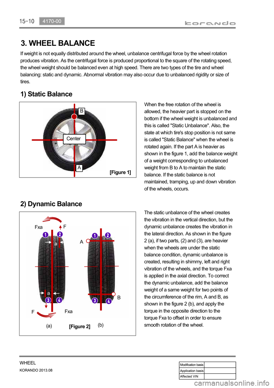
When the free rotation of the wheel is
allowed, the heavier part is stopped on the
bottom if the wheel weight is unbalanced and
this is called "Static Unbalance". Also, the
state at which tire's stop position is not same
is called "Static Balance" when the wheel is
rotated again. If the part A is heavier as
shown in the figure 1, add the balance weight
of a weight corresponding to unbalanced
weight from B to A to maintain the static
balance. If the static balance is not
maintained, tramping, up and down vibration
of the wheels, occurs.
2) Dynamic Balance
The static unbalance of the wheel creates
the vibration in the vertical direction, but the
dynamic unbalance creates the vibration in
the lateral direction. As shown in the figure
2 (a), if two parts, (2) and (3), are heavier
when the wheels are under the static
balance condition, dynamic unbalance is
created, resulting in shimmy, left and right
vibration of the wheels, and the torque Fxa
is applied in the axial direction. To correct
the dynamic unbalance, add the balance
weight of a same weight for two points of
the circumference of the rim, A and B, as
shown in the figure 2 (b), and apply the
torque in the opposite direction to the
torque Fxa to offset in order to ensure
smooth rotation of the wheel.
Center
A
B
a
a
Fxa
Fxa F
F
A
B
(a)(b)
[Figure 1]
[Figure 2]
3. WHEEL BALANCE
Page 1170 of 1336
4190-00
1. SPECIFICATIONS
Unit Item Specification Remarks
TPMS ECUVoltage range 9 ~ 16 V -
Active mode 50 mA -
Coast mode 30 mA -
Sleep mode 100 uA -
Bit rate 500 Kbps -
Modulation type Amplitude modulation (AM) -
Frequency 433.92 Mhz -
Wheel modulePressure measuring
range0 ~ 6.375 bar
(0~92.43 psi)1 bar = about 14.5 psi
Tolerance range of
measured pressure
-
Tolerance range of
measured temperature
-
Temperature
measuring range
-
Battery lifeLithium battery
(about 3.0~3.2 V),
160,000 km or 10 yearsIt can be shortened
depending on use
condition.
Tire Inflation pressure 32 psi -
Page 1171 of 1336
How to use
Torque wrench To remove and install valve insert
To remove and install valve body
2. SPECIAL TOOL FOR TPMS SYSTEM
The following torque wrench and connecting adapter should be prepared when installing the TPMS
wheel module.
Torque wrench (0.1~5.0 Nm)
E-socket T-10
Tire valve changer
When fitting the wheel module, tighten the mounting bolt to the specified tightening torque (1.4 Nm)
to prevent the wheel module from being damaged due to excessive tightening.
Page 1172 of 1336

4190-00
3. CAUTIONS
The tire pressure values displayed on the instrument cluster are sent from the wheel modules after
the vehicle is driven for a period of time. Therefore, they are not displayed at initial start (more than
20 minutes have elapsed after ignition off). It can be displayed after 10 minutes of driving at speed of
20 km/h or higher. -
The TPMS uses a radio frequency and a high frequency band between the wheel module and the
TPMS ECU for communication.
Therefore, if the vehicle is equipped with the electronic equipment such as mobile camera monitor
or the vehicle is passing through the area with a strong electromagnetic field, the system may not
operate normally.
For the vehicle equipped with the TPMS, the TPMS warning lamp on the instrument cluster comes
on and pressure values on the EL display is displayed as bars (--) after driving for a certain period of
time if a newly installed tire is not equipped with the wheel module. -
-
At initial startDisplay pressure value after
detecting
position automatically
Standard type
Supervision type
Page 1173 of 1336
Mounted view
If the vehicle is equipped with the TPMS, all wheels are equipped with the wheel modules. In this
case, the wheel module may be interfered with the wheel rim depending on the mounting surface
type of the rim. Therefore, always use the SYMC genuine wheel and wheel module for the vehicle. -
Clean the wheel mounting surface and inner side of the wheel thoroughly when replacing the tires.
However, never inject the commercial anti-flat fluid or similar substance. It may cause a critical error
to the wheel module. -
Page 1175 of 1336
Instrument cluster display related to TPMS (with standard)
DOT LCD display TPMS warning lamp Global warning lamp
2. LAYOUT 1. OVERVIEW
The TPMS is used to reduce the accident rate, enhance driving stability and avoid an unnecessary fuel
consumption and tire wear by monitoring the tire pressure and temperature to inform the driver of tire
pressure information and its status through the instrument cluster. The wheel module fitted in the tire
transmits the internal data for the tire to the TPMS ECU periodically through the wireless transmission.
The TPMS ECU can detect the positions of the wheel modules fitted to each wheel automatically and
sends the signal on tire condition through the CAN line to the instrument cluster so that the driver can
identify the wheel module in question.
Instrument cluster display related to TPMS (with supervision)
DOT LCD display TPMS warning lamp Global warning lamp
Page 1176 of 1336
4190-00
Wheel module
The wheel modules are mounted to each wheel rim and hole.
TPMS ECU
The TPMS ECU is mounted to the rear bumper beam.
Page 1178 of 1336

4190-00
4. TPMS PRESSURE VALUE DISPLAYING PROCESS
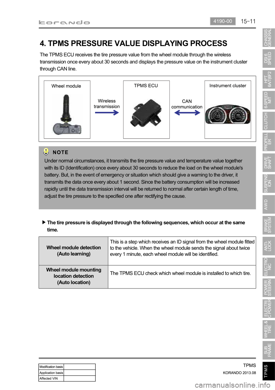
The TPMS ECU receives the tire pressure value from the wheel module through the wireless
transmission once every about 30 seconds and displays the pressure value on the instrument cluster
through CAN line.
Under normal circumstances, it transmits the tire pressure value and temperature value together
with its ID (Identification) once every about 30 seconds to reduce the load on the wheel module's
battery. But, in the event of emergency or situation which should give a warning to the driver, it
transmits the data once every about 1 second. Since the battery consumption will be increased
rapidly until the data transmission interval will be returned to normal after certain length of time,
adjust the tire pressure to the specified one after rectifying the cause.
The tire pressure is displayed through the following sequences, which occur at the same
time.
Wheel module detection
(Auto learning)This is a step which receives an ID signal from the wheel module fitted
to the vehicle. When the wheel module sends the signal about twice
every 1 minute, each wheel module will be identified.
Wheel module mounting
location detection
(Auto location)The TPMS ECU check which wheel module is installed to which tire.