Page 1132 of 1336
0000-00
5) ARP (Active Roll-Over Protection)
The ARP (Active Roll-over Protection) system is a safety assistant device that minimizes, by controlling
brakes and the engine, the physical tendency of the vehicle rollover during sharp lane changes or U-
turns. For the system, software is added to the existing ESP system and no additional device or switch is
needed. One must note that the ARP system, just as general assistant devices including the ABS, is only
a safety assistant device using the ESP system and its function is useless when the situation overcomes
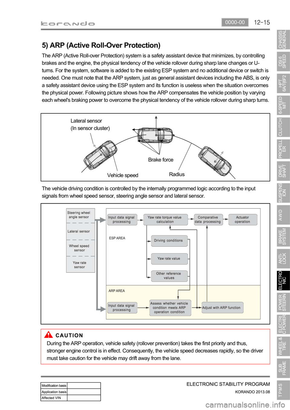
the physical power. Following picture shows how the ARP compensates the vehicle position by varying
each wheel's braking power to overcome the physical tendency of the vehicle rollover during sharp turns.
Lateral sensor
(In sensor cluster)
Vehicle speedBrake force
Radius
The vehicle driving condition is controlled by the internally programmed logic according to the input
signals from wheel speed sensor, steering angle sensor and lateral sensor.
During the ARP operation, vehicle safety (rollover prevention) takes the first priority and thus,
stronger engine control is in effect. Consequently, the vehicle speed decreases rapidly, so the driver
must take caution for the vehicle may drift away from the lane.
Page 1135 of 1336
The BCM flashes the emergency auto hazard flasher with interval of 1.25 times/sec.:
The emergency hazard flasher does not operate if the vehicle speed is over 50 km/h when the
emergency stop signal is received.
The emergency hazard flasher operates if the vehicle speed is 50 km/h or lower when the
emergency stop signal is received.
When vehicle speed increases more than 10 km/h above the speed when the signal is received
during operation by emergency braking signal, the emergency hazard flasher stops operation.
When turning emergency hazard flasher switch OFF during operation by emergency braking signal,
it stops operation.
It is deactivated automatically 10 seconds after if items 2) and 3) above are not met during operation
by emergency braking signal.
If multi-function automatic hazard flasher signal is received during operation by emergency braking
signal, it will be overridden. -
-
-
-
-
-
Page 1153 of 1336
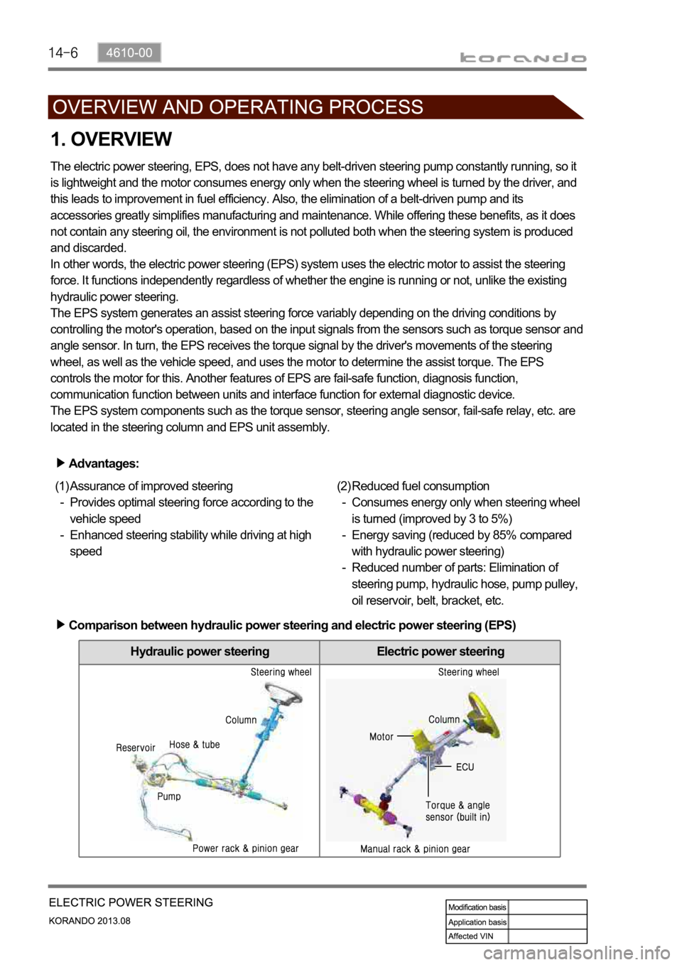
Hydraulic power steering Electric power steering
1. OVERVIEW
The electric power steering, EPS, does not have any belt-driven steering pump constantly running, so it
is lightweight and the motor consumes energy only when the steering wheel is turned by the driver, and
this leads to improvement in fuel efficiency. Also, the elimination of a belt-driven pump and its
accessories greatly simplifies manufacturing and maintenance. While offering these benefits, as it does
not contain any steering oil, the environment is not polluted both when the steering system is produced
and discarded.
In other words, the electric power steering (EPS) system uses the electric motor to assist the steering
force. It functions independently regardless of whether the engine is running or not, unlike the existing
hydraulic power steering.
The EPS system generates an assist steering force variably depending on the driving conditions by
controlling the motor's operation, based on the input signals from the sensors such as torque sensor and
angle sensor. In turn, the EPS receives the torque signal by the driver's movements of the steering
wheel, as well as the vehicle speed, and uses the motor to determine the assist torque. The EPS
controls the motor for this. Another features of EPS are fail-safe function, diagnosis function,
communication function between units and interface function for external diagnostic device.
The EPS system components such as the torque sensor, steering angle sensor, fail-safe relay, etc. are
located in the steering column and EPS unit assembly.
Advantages:
Assurance of improved steering
Provides optimal steering force according to the
vehicle speed
Enhanced steering stability while driving at high
speed (1)
-
-Reduced fuel consumption
Consumes energy only when steering wheel
is turned (improved by 3 to 5%)
Energy saving (reduced by 85% compared
with hydraulic power steering)
Reduced number of parts: Elimination of
steering pump, hydraulic hose, pump pulley,
oil reservoir, belt, bracket, etc. (2)
-
-
-
Comparison between hydraulic power steering and electric power steering (EPS)
Page 1178 of 1336
4190-00
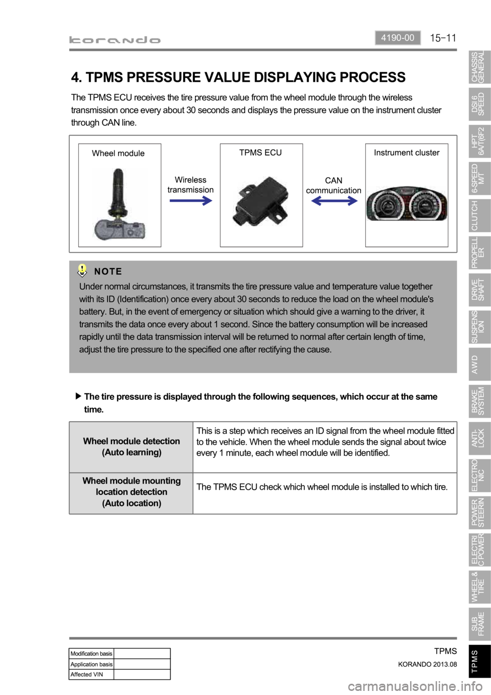
4. TPMS PRESSURE VALUE DISPLAYING PROCESS
The TPMS ECU receives the tire pressure value from the wheel module through the wireless
transmission once every about 30 seconds and displays the pressure value on the instrument cluster
through CAN line.
Under normal circumstances, it transmits the tire pressure value and temperature value together
with its ID (Identification) once every about 30 seconds to reduce the load on the wheel module's
battery. But, in the event of emergency or situation which should give a warning to the driver, it
transmits the data once every about 1 second. Since the battery consumption will be increased
rapidly until the data transmission interval will be returned to normal after certain length of time,
adjust the tire pressure to the specified one after rectifying the cause.
The tire pressure is displayed through the following sequences, which occur at the same
time.
Wheel module detection
(Auto learning)This is a step which receives an ID signal from the wheel module fitted
to the vehicle. When the wheel module sends the signal about twice
every 1 minute, each wheel module will be identified.
Wheel module mounting
location detection
(Auto location)The TPMS ECU check which wheel module is installed to which tire.
Page 1209 of 1336
6810-00
(6) A/C control
The air conditioner is controlled by the A/C compressor of the engine ECU according to the signal from
the heater and A/C control assembly. The driver can see the air conditioner operation through the LCD
display and the indicator of the A/C switch.
Manual control
Pressing the A/C switch or selecting defrost mode turns on the A/C.
Auto control
The A/C is controlled in accordance with the indoor temperature and ambient temperature.
or below) in winter, the compressor is turned off to protect the A/C compressor.
A/C switch
LCD display (A/C operation view)
Page 1220 of 1336
(6) A/C control
The air conditioner is operated at the defroster mode and MAX air conditioner mode and when the A/C
switch is turned to "ON" position. It is controlled by the A/C compressor of the engine ECU according to
the signal from the heater and A/C control assembly. The driver can see that the A/C has been activated
when an indicator lamps at the A/C switch and MAX A/C switch comes on. If the intake sensor detects
the freezing of the evaporator core, it stops the air conditioner by turning off the compressor.
MAX A/C control
This is designed for increasing driver comfort. When the switch is pressed, the air conditioner is
operated and vent and recirculation modes are selected automatically. The discharge temperature and
fan speed are regulated depending on the driver's choice.
A/C switch
MAX A/C control switch
Page 1232 of 1336
8810-00
1. AIR BAG SYSTEM OVERVIEW
The air bag system is divided into front air bag system and side air bag system. The system protects the
occupant's body by deploying the air bags in the event of a collision. The system consists of 8 inflators
including the inflators of the seat belt pretensioners, air bag unit (SDM), and 4 impact sensors on the
front side and both sides of the vehicle. The air bag unit (SDM) determines the operation of each air bag
module and seat belt pretensioners using the crash signals from the front and side impact sensors in the
event of a collision. The front and side air bag systems are operated independently, and the body control
module (BCM) activates the auto door unlock function and various lamps including hazard warning lamp
and room lamps, when the crash signal from the SDM is received to notify others of emergency situation
and let the occupant escape easily. The SDM is equipped with self diagnosis function, and it performs
the diagnosis on the internal/external devices of the air bag system for a certain period of time after IGN
ON. And it monitors the air bag system regularly and turns on the air bag warning lamp on the
instrument cluster when a fault is found in the system, to notify the driver. The SDM has event data
recorder (EDR) function that stores the driving information data transmitted through CAN communication
from various units (vehicle speeds, engine rpm, brake application, etc.) in a crash or near crash event,
when the acceleration sensor in the air bag unit detects a sharp acceleration change, regardless of the
air bag deployment
Page 1233 of 1336
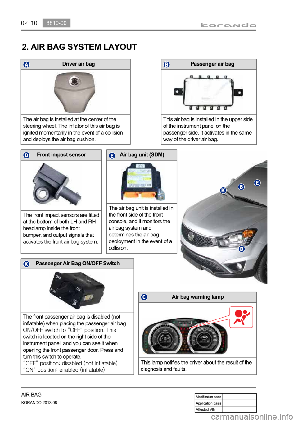
Driver air bag
The air bag is installed at the center of the
steering wheel. The inflator of this air bag is
ignited momentarily in the event of a collision
and deploys the air bag cushion.
Air bag unit (SDM)
The air bag unit is installed in
the front side of the front
console, and it monitors the
air bag system and
determines the air bag
deployment in the event of a
collision.Front impact sensor
The front impact sensors are fitted
at the bottom of both LH and RH
headlamp inside the front
bumper, and output signals that
activates the front air bag system.
Air bag warning lamp
This lamp notifies the driver about the result of the
diagnosis and faults.
Passenger air bag
This air bag is installed in the upper side
of the instrument panel on the
passenger side. It activates in the same
way of the driver air bag.
2. AIR BAG SYSTEM LAYOUT
Passenger Air Bag ON/OFF Switch
The front passenger air bag is disabled (not
inflatable) when placing the passenger air bag
switch is located on the right side of the
instrument panel, and you can see it when
opening the front passenger door. Press and
turn this switch to operate.