Page 1121 of 1336
2) Specification of Steering Wheel Angle Sensor
Description Specification
Operating voltage 9 to 16 V
Maximum output current 10 mA
Maximum detection angle speed
Operating temperature
Supplying voltage 9 to 16 V (battery voltage)
Output voltage (HI) approx. 3.50 V (3.0 to 4.1 V)
Output voltage (LO) approx. 1.50 V (1.3 to 2.0 V)
Pulses/rev 45 pulses/rev
3) Specification of Sensor Cluster
Description Specification
Supplying voltage approx. 12 V (8 to 16 V)
Current consumption below 250 mA -
Operating range Yaw rate sensor
Lateral/longitudinal sensor
Page 1170 of 1336
4190-00
1. SPECIFICATIONS
Unit Item Specification Remarks
TPMS ECUVoltage range 9 ~ 16 V -
Active mode 50 mA -
Coast mode 30 mA -
Sleep mode 100 uA -
Bit rate 500 Kbps -
Modulation type Amplitude modulation (AM) -
Frequency 433.92 Mhz -
Wheel modulePressure measuring
range0 ~ 6.375 bar
(0~92.43 psi)1 bar = about 14.5 psi
Tolerance range of
measured pressure
-
Tolerance range of
measured temperature
-
Temperature
measuring range
-
Battery lifeLithium battery
(about 3.0~3.2 V),
160,000 km or 10 yearsIt can be shortened
depending on use
condition.
Tire Inflation pressure 32 psi -
Page 1178 of 1336
4190-00
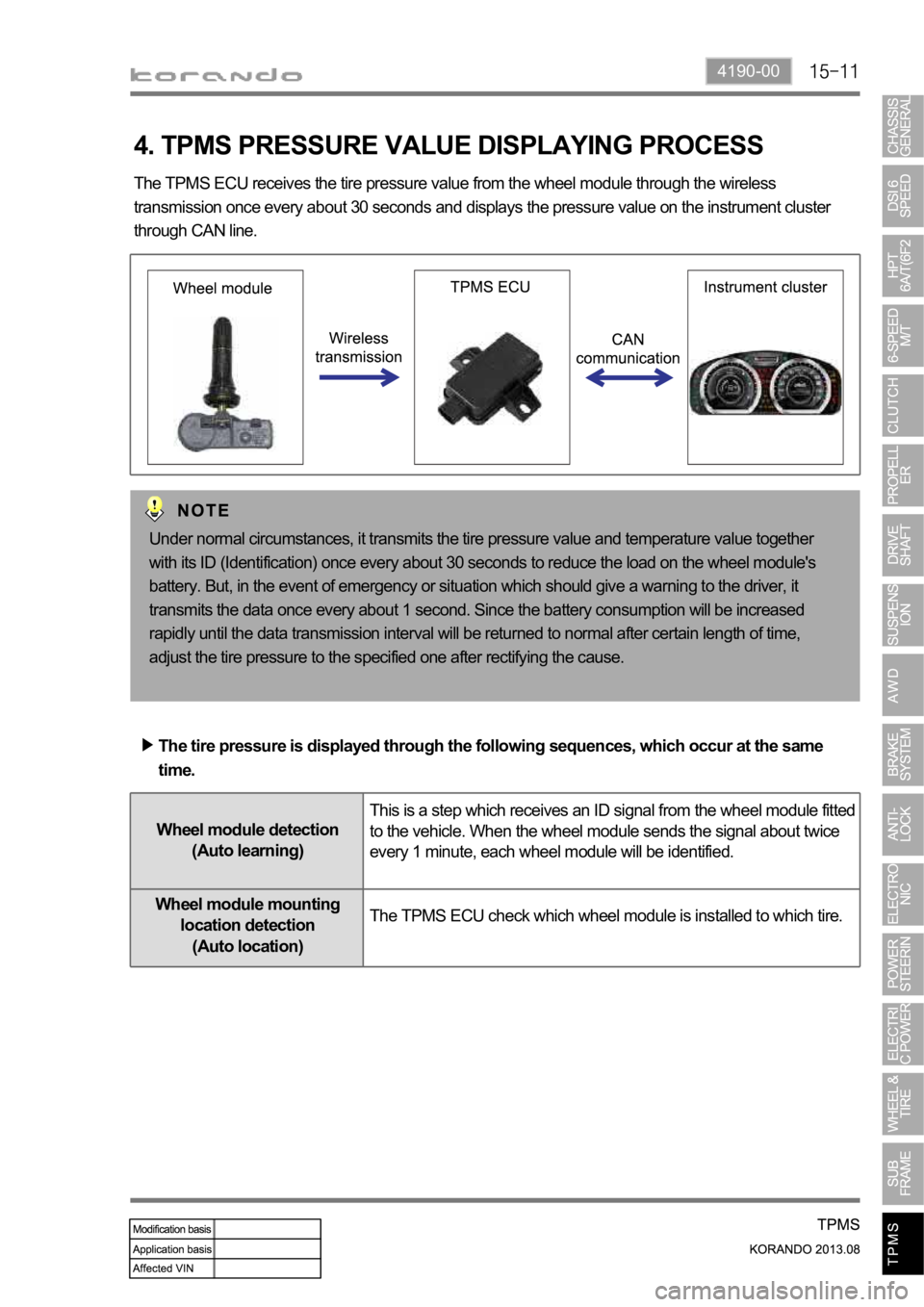
4. TPMS PRESSURE VALUE DISPLAYING PROCESS
The TPMS ECU receives the tire pressure value from the wheel module through the wireless
transmission once every about 30 seconds and displays the pressure value on the instrument cluster
through CAN line.
Under normal circumstances, it transmits the tire pressure value and temperature value together
with its ID (Identification) once every about 30 seconds to reduce the load on the wheel module's
battery. But, in the event of emergency or situation which should give a warning to the driver, it
transmits the data once every about 1 second. Since the battery consumption will be increased
rapidly until the data transmission interval will be returned to normal after certain length of time,
adjust the tire pressure to the specified one after rectifying the cause.
The tire pressure is displayed through the following sequences, which occur at the same
time.
Wheel module detection
(Auto learning)This is a step which receives an ID signal from the wheel module fitted
to the vehicle. When the wheel module sends the signal about twice
every 1 minute, each wheel module will be identified.
Wheel module mounting
location detection
(Auto location)The TPMS ECU check which wheel module is installed to which tire.
Page 1221 of 1336
6810-00
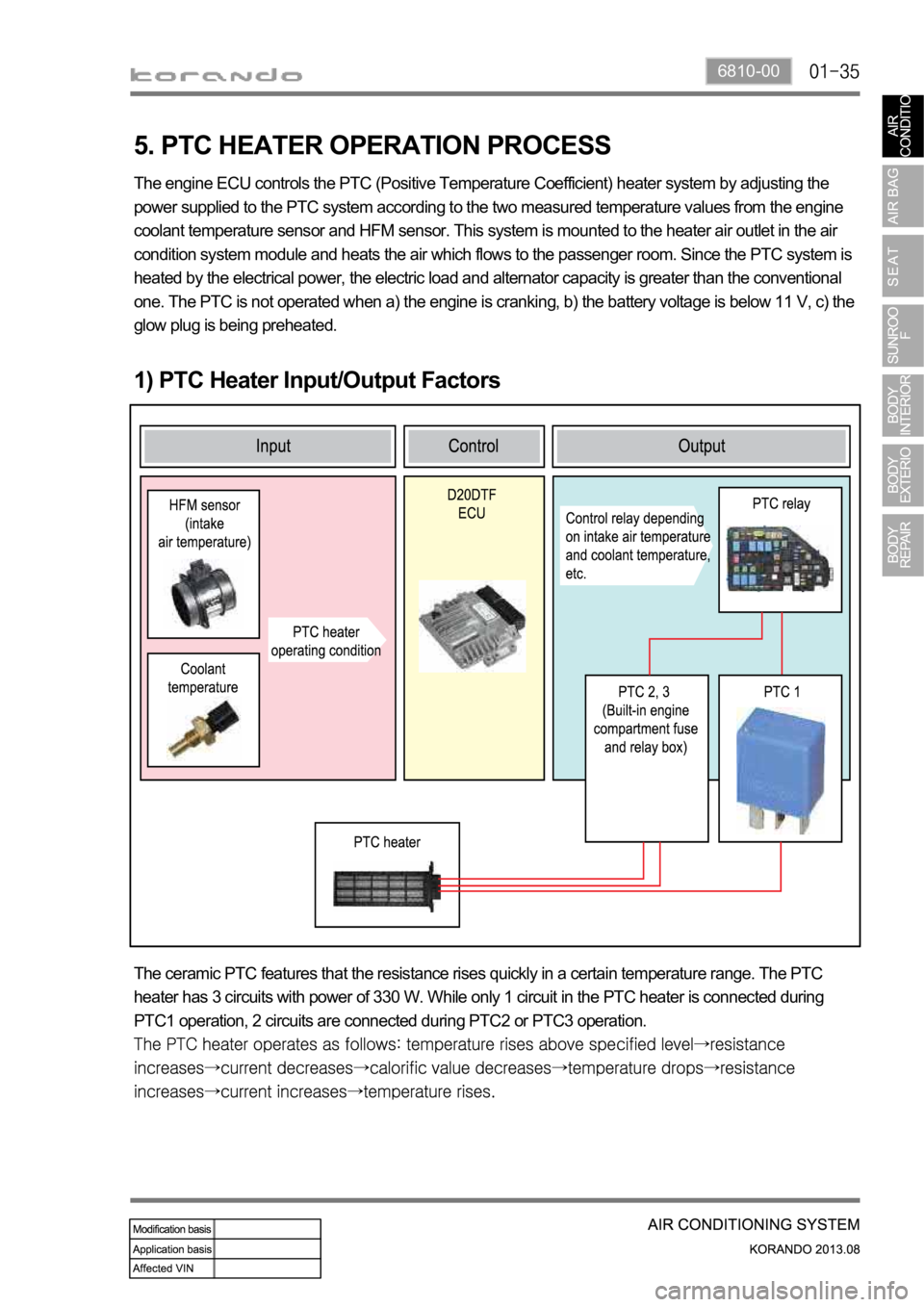
5. PTC HEATER OPERATION PROCESS
1) PTC Heater Input/Output Factors
The engine ECU controls the PTC (Positive Temperature Coefficient) heater system by adjusting the
power supplied to the PTC system according to the two measured temperature values from the engine
coolant temperature sensor and HFM sensor. This system is mounted to the heater air outlet in the air
condition system module and heats the air which flows to the passenger room. Since the PTC system is
heated by the electrical power, the electric load and alternator capacity is greater than the conventional
one. The PTC is not operated when a) the engine is cranking, b) the battery voltage is below 11 V, c) the
glow plug is being preheated.
The ceramic PTC features that the resistance rises quickly in a certain temperature range. The PTC
heater has 3 circuits with power of 330 W. While only 1 circuit in the PTC heater is connected during
PTC1 operation, 2 circuits are connected during PTC2 or PTC3 operation.
Page 1222 of 1336
2) Control Condition For PTC Heater
Operation Operating condition PTC heater status
HI mode operation
(PTC2, 3)PTC heater operates in
"HIGH" mode if operating
conditions are met
LO mode operation
(PTC1)PTC heater operates in
"LOW" mode if operating
conditions are met
Conditions for
deactivating
Air conditioner blower switch OFF
When the ambient temperature sensor is
faulty (short or open circuit in the wiring)
Engine is cranking
Battery voltage is 11 V or less
Glow plug is being preheated (Glow indicator
comes on) -
-
-
-
-
-
-
-
-
Conditions for PTC heater "LOW" operation mode (2nd step)
Page 1229 of 1336
3. CAUTIONS FOR AIR BAG SYSTEM
Cautions for air bag maintenance
Whenever installing or removing the devices related to the air bag system, disconnect the negative
battery cable and wait for at least 30 seconds.
Do not connect a tester probe to the inflator to measure the resistance of the component of the air
bag system. The detonator of the inflator may explode due to a sudden extra power supplied by the
tester.
Note that the used components related to the air bag system, especially the air bag unit, should be
packed in an air tight container and prevent it from any impact or damage.
When there is any deployed air bag (including curtain air bag and seat belt pretensioner), the entire
system including the air bag unit should be replaced. The deployed air bag unit should not be reused
since it has status data when it is deployed, and the data cannot be cleared with a diagnostic device.
The air bag and seat belt pretensioner systems contain explosive charges, so handle carefully when
disposing or replacing them. 1.
2.
3.
4.
5.
Cautions for air bag maintenance
Do not modify, change or apply impact on any air bag component. The air bag may be deployed
abruptly, causing serious injuries.
Children and infants should ride in a rear seat. Seating in the passenger seat with carrying a
child or infant is strictly prohibited. An infant or a child could be severely injured by the air bag
deployment.
A child restraint system must not be installed on the front seat. An infant or a child could be severely
injured by the air bag deployment when it is fitted to the passenger seat.
Do not place any objects on the air bag inflation location. You may get injured by those objects during
deployment.
Never put your arms around the front seat from behind, lean on the front seatback, or put your arms
out of the window. You can severely injured when the side air bag deploys.
Never lean on the door since it becomes very dangerous when the side air bag deploys.
The side air bag deploys when there is a severe side collision.
Do not slam the front door to close it. The side air bag may deploy unexpectedly.
When an occupant fastens the seat belt in an unstable or inclined posture, the air bag system cannot
protect the occupant properly. Moreover, the occupant can be injured by the air bag.
Do not move your seat too close to the steering wheel or dashboard. Being too close to the
steering wheel or instrument panel during the air bag deployment could cause serious injury,
including death
Hold only the outer rim of the steering so that the air bag can inflate without any hindrance.
Do not incline toward the steering wheel. Never allow the passenger to put hands or feet on the dash
board. The air bag cannot work properly Do not hold and operate the steering wheel by crossing your
arms You could get seriously injured when the air bag deploys. 1.
2.
3.
4.
5.
6.
7.
8.
9.
10.
11.
Page 1244 of 1336
8810-00
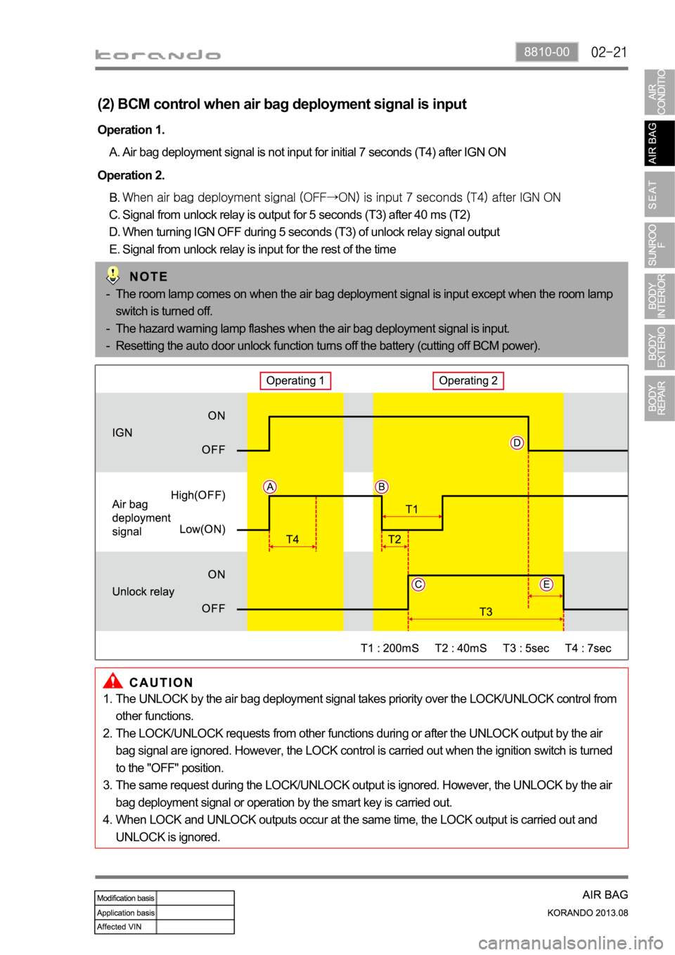
Operation 2.
Signal from unlock relay is output for 5 seconds (T3) after 40 ms (T2)
When turning IGN OFF during 5 seconds (T3) of unlock relay signal output
Signal from unlock relay is input for the rest of the time B.
C.
D.
E. Operation 1.
Air bag deployment signal is not input for initial 7 seconds (T4) after IGN ON A.
The room lamp comes on when the air bag deployment signal is input except when the room lamp
switch is turned off.
The hazard warning lamp flashes when the air bag deployment signal is input.
Resetting the auto door unlock function turns off the battery (cutting off BCM power). -
-
-
(2) BCM control when air bag deployment signal is input
The UNLOCK by the air bag deployment signal takes priority over the LOCK/UNLOCK control from
other functions.
The LOCK/UNLOCK requests from other functions during or after the UNLOCK output by the air
bag signal are ignored. However, the LOCK control is carried out when the ignition switch is turned
to the "OFF" position.
The same request during the LOCK/UNLOCK output is ignored. However, the UNLOCK by the air
bag deployment signal or operation by the smart key is carried out.
When LOCK and UNLOCK outputs occur at the same time, the LOCK output is carried out and
UNLOCK is ignored. 1.
2.
3.
4.
Page 1245 of 1336
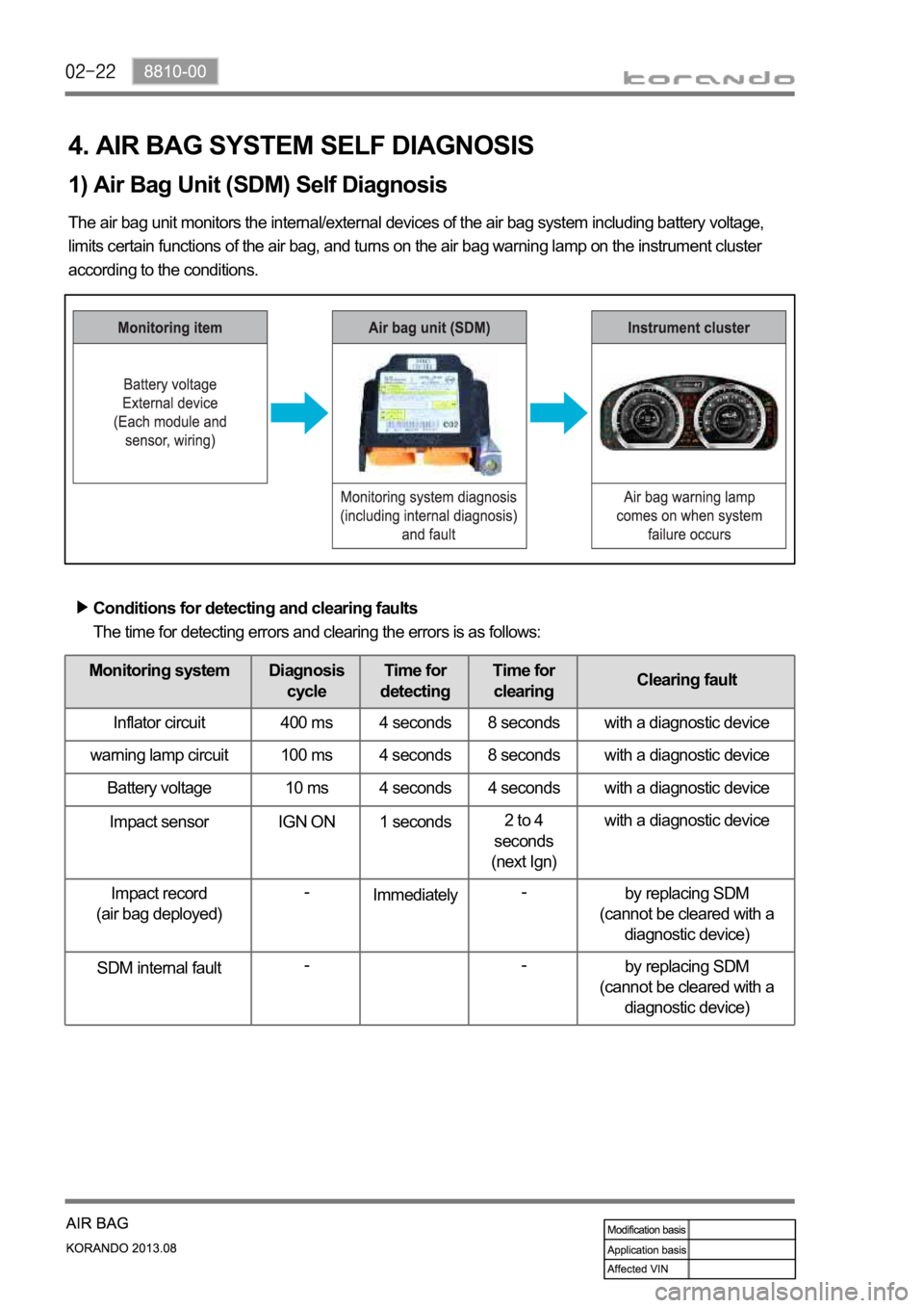
4. AIR BAG SYSTEM SELF DIAGNOSIS
1) Air Bag Unit (SDM) Self Diagnosis
The air bag unit monitors the internal/external devices of the air bag system including battery voltage,
limits certain functions of the air bag, and turns on the air bag warning lamp on the instrument cluster
according to the conditions.
Conditions for detecting and clearing faults
The time for detecting errors and clearing the errors is as follows:
Monitoring system Diagnosis
cycleTime for
detectingTime for
clearingClearing fault
Inflator circuit 400 ms 4 seconds 8 seconds with a diagnostic device
warning lamp circuit 100 ms 4 seconds 8 seconds with a diagnostic device
Battery voltage 10 ms 4 seconds 4 seconds with a diagnostic device
Impact sensor IGN ON 1 seconds2 to 4
seconds
(next Ign)with a diagnostic device
Impact record
(air bag deployed)-
Immediately-
by replacing SDM
(cannot be cleared with a
diagnostic device)
SDM internal fault--
by replacing SDM
(cannot be cleared with a
diagnostic device)