2013 SMART FORTWO COUPE ELECTRIC DRIVE service
[x] Cancel search: servicePage 18 of 218
For safety reasons, smart recommends all
work to be carried out by a smart service
partner which is qualified for smart
electric drive.
Particular care should be taken involving
all areas which are in the vicinity of high
voltage parts, e.g. parts in the engine
compartment. Orange-colored cables and
their respective sockets carry high voltage
and must not be damaged.
Serious injury or death can result if you:
R
remove the covers of components which
are labeled with a warning sticker.
R handle components of the high-voltage
vehicle electrical system.
R open the housing.
R disconnect plug connectors.
R come into contact with components or
orange-colored cables of the high-
voltage vehicle electrical system
following an accident.
R come into contact with orange-colored
cables or their damage dplug connectors.
R come into contact with damaged
components of the high-voltage vehicle
electrical system.
Have the damaged orange-colored cables or
their damaged plug connectors replaced
immediately at an authorized electric
drive smart center. The service partner
must have the required knowledge and tools
to carry out the necessary work. For safety
reasons, smart recommends using a smart
center which is qualified for smart
electric drive. Particularly for safety-
relevant work and work on safety-relevant
vehicle systems, servicing by an
authorized electric drive smart center is
essential.
Do not remove the high-voltage battery of
the high-voltage vehicle electrical
system. Have the required work carried out
by an authorized electric drive smart
center. smart recommends that you use an
authorized electric drive smart center. G
WARNING
The high‑voltage battery of the drive
system is located under the vehicle’s
underbody. When the pressure inside the
high‑voltage battery exceeds a certain
value, for example in case of avehicle fire,
inflammable gas will escape via a duct. The
inflammable gas escapes to an area under
the vehicle. This prevents the high‑voltage
battery from exploding.
Stay away from this area of the vehicle. Automatic switch-off of the high-
voltage system
The high-voltage system will be
automatically switched off, in the event:
R of an accident in which the restraint
systems are triggered
R of a short circuit in the high-voltage
system is detected
R that an electric connection in the high-
voltage system has been disconnected
This helps to avoid that you get in contact
with high-voltage. High-voltage battery
G
WARNING
The high‑voltage battery of the drive
system is located under the vehicle’s
underbody. When the pressure inside the
high‑voltage battery exceeds a certain
value, for example in case of avehicle fire,
inflammable gas will escape via a duct. The
inflammable gas escapes to an area under
the vehicle. This prevents the high‑voltage
battery from exploding.
Stay away from this area of the vehicle. 16
>> Introduction.
Page 19 of 218

High-voltage disconnect device
Your vehicle is equipped with a high-
voltage disconnect device 0002to disable
the vehicle’s high-voltage system.
! The high-voltage system must only be
switched off at vehicle standstill by
specially trained service engineers.
Otherwise the high-voltage system may
be damaged. Proper use of the vehicle
Proper use of the vehicl erequires that you
are familiar with the following
information and rules:
R the safety precautions in this manual
R the “Technical data” section in this
manual
R traffic rules and regulations
R motor vehicle laws and safety standards G
WARNING
Various warning labels are attached to your
vehicle. These warning labels are intended
to make you and others aware of various
risks. You should not remove any of these
warning labels unless explicitly
instructed to do so by information on the
label itself. Removal of any of these labels
may cause you and others to be unaware of
certain risks which may result in an
accident and/or personal injury. Problems with your vehicle
If you should experience a problem with
your vehicle, particularly one that you
believe may affect its safe operation, we
urge you to immediately contact an
authorized electric drive smart center to
have the problem diagnosed and corrected
if required. Do not drive the vehicle if you
believe it may not be safely operated. If the
matter is not handled to your satisfaction,
please discuss the problem with the smart
center management, or if necessary contact
us at one of the following addresses:
In the USA:
Daimler Vehicle Innovations USA LLC
One Mercedes Drive
Montvale, NJ 07645
In Canada:
Customer Relations Department
98 Vanderhoof Avenue
Mercedes-Benz Canada, Inc.
Toronto, Ontario, M4G 4C9 Reporting safety defects
For the USA only: The following text is
published as required of manufacturers
under Title 49, Code of U.S. Federal
Regulations, Part 575 pursuant to the
National Traffic and Motor Vehicle Safety
Act of 1966.
If you believe that your vehicle has adefect
which could cause a crash or could cause
injury or death, you should immediately
inform the National Highway Traffic Safety
Administration (NHTSA) in addition to
notifying Daimler Vehicle Innovations USA
LLC.
If NHTSA receives similar complaints, it
may open an investigation, and if it finds
that a safety defect exists in a group of
vehicles, it may order a recall and remedy
campaign. However, NHTSA cannot become >> Introduction.
17 Z
Page 20 of 218
involved in individual problems between
you, your dealer, or Daimler Vehicle
Innovations USA LLC.
To contact NHTSA, you may call the Vehicle
Safety Hotline toll-free at 1-888-327-4236
(TTY: 1-800-424-9153); go to
http://www.safercar.gov ; or write to:
Administrator, NHTSA Headquarters, 1200
New Jersey Avenue, SE, West Building,
Washington, DC 20590. You can also obtain
other information about motor vehicle
safety from http://www.safercar.gov. Vehicle data recording
Information regarding electronic
recording devices
(Including notice pursuant to California
Code § 9951)
Please note that your vehicle is equipped
with devices that can record vehicle
systems data.
This information helps, for example, to
diagnose vehicle systems after a collision
and to continuously improve vehicle
safety.
smart may access the information and share
it with others
R for safety research or vehicle diagnosis
purposes
R with the consent of the vehicle owner or
lessee
R in response to an official request by law
enforcement or other governmen tagency
R for use in dispute resolution involving
smart, its affiliates or sales/service
organization and/or
R as otherwise required or permitted by
law 18
>> Introduction.
Page 39 of 218

Thorax-pelvis side air bags
Thorax-pelvis side air bags are designed
to provide increased protection for the
thorax and pelvis, but not the arms.
Thorax-pelvis side air bags are deployed
R on the impacted side of the vehicle
R in instances with a high rate of lateral
vehicle deceleration or acceleration
R independently of the front air bags
R regardless of whether the seat belt on the
impacted side of the vehicle is in use
R independently of the ETDs.
Thorax-pelvis side air bags will generally
not deploy in a rollover.
The thorax-pelvis side air bags will
deploy, however, if the system detects
R a high rate of lateral vehicle
deceleration or acceleration, and
R that air bag deployment can offer
additional protection to that provided
by the seat belt.
The thorax-pelvis side air bags are
integrated into the driver and passenger
seat backrests. 0002
Thorax-pelvis side air bags Occupant Classification System
The Occupant Classification System (OCS)
automatically turns the passenger front air
bag on or off based on the classified
occupant weight category determined by weight sensor readings from the passenger
seat.
i
Based on the classified occupant
weight category determined by weight
sensor readings from the passenger seat,
the system does also deactivate
R head-thorax air bag (cabriolet)
R the window curtain air bag (coupé)
R the thorax-pelvis side air bag (coupé)
R the seat Emergency Tensioning
Devices
R the seat belt force limiter.
Occupants must sit properly belted in a
position that is as upright as possible with
their back against the seat backrest and
feet on the floor to be correctly classified.
If the occupant’s weight is transferred to
another object in the vehicle (e.g. by
leaning on armrests), the OCS may not be
able to properly approximate the
occupant’s weight category.
i If the seat, including the trim cover and
cushion, needs to be serviced in any way,
take the vehicle to an authorized
electric drive smart center. Only seat
accessories approved by smart may be
used.
Both driver and the passenger should
always use the 00090007indicator
lamp as an indication of whether or not
the passenger is properly positioned
(Y page 39). G
WARNING
If the 00090007indicator lamp
illuminates when an adult or someone
larger than a small individual is in the
passenger seat, have the passenger re-
position himself or herself in the seat
until the 00090007indicator lamp
goes out.
In the event of a collision, the air bag
control unit will not allow passenger front
air bag deployment when the OCS has
classified the passenger seat occupant as Occupant safety
37>> Safety.
Z
Page 91 of 218
i
You can also set the maximum charge
current via the control element on the
charging cable (Y page 113).
If differing values are set on the
charging cable and the control system,
the high‑voltage battery is charged
using the lowest value.
i If the vehicle needs more time to charge
the high‑voltage battery than usual,
check the settings of the maximum
permissible charge current. Messages menu
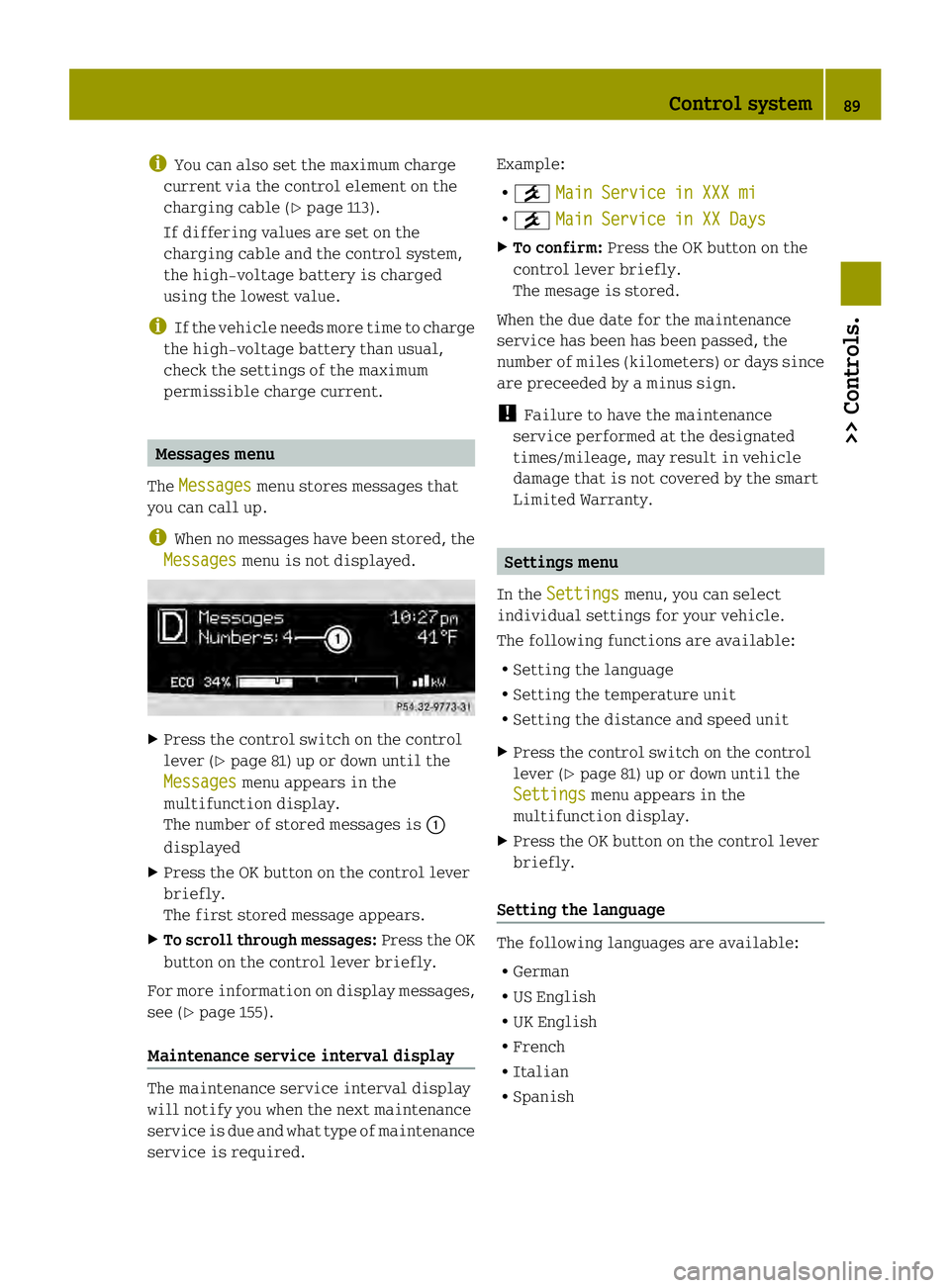
The Messages menu stores messages that
you can call up.
i When no messages have been stored, the
Messages menu is not displayed.
X
Press the control switch on the control
lever (Y page 81) up or down until the
Messages menu appears in the
multifunction display.
The number of stored messages is 0002
displayed
X Press the OK button on the control lever
briefly.
The first stored message appears.
X To scroll through messages: Press the OK
button on the control lever briefly.
For more information on display messages,
see (Y page 155).
Maintenance service interval display The maintenance service interval display
will notify you when the next maintenance
service is due and what type of maintenance
service is required. Example:
R
0004 Main Service in XXX mi R
0004 Main Service in XX Days X
To confirm: Press the OK button on the
control lever briefly.
The mesage is stored.
When the due date for the maintenance
service has been has been passed, the
number of miles (kilometers) or days since
are preceeded by a minus sign.
! Failure to have the maintenance
service performed at the designated
times/mileage, may result in vehicle
damage that is not covered by the smart
Limited Warranty. Settings menu
In the Settings menu, you can select
individual settings for your vehicle.
The following functions are available:
R Setting the language
R Setting the temperature unit
R Setting the distance and speed unit
X Press the control switch on the control
lever (Y page 81) up or down until the
Settings menu appears in the
multifunction display.
X Press the OK button on the control lever
briefly.
Setting the language The following languages are available:
R
German
R US English
R UK English
R French
R Italian
R Spanish Control system
89>> Controls. Z
Page 110 of 218
High-voltage battery
Introduction
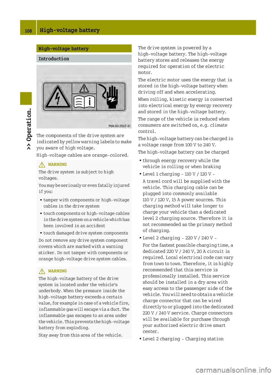
The components of the drive system are
indicated by yellow warning labels to make
you aware of high voltage.
High‑voltage cablesa
re orange‑colored.G
WARNING
The drive system is subject to high
voltages.
You may be seriously or even fatally injured
if you:
R tamper with components or high-voltage
cables in the drive system
R touch components or high-voltage cables
in the drive system on avehicle which has
been involved in an accident
R touch damaged drive system components
Do not remove any drive system component
covers which are marked with a warning
sticker. Do not tamper with components or
orange high-voltage drive system cables. G
WARNING
The high‑voltage battery of the drive
system is located under the vehicle’s
underbody. When the pressure inside the
high‑voltage battery exceeds a certain
value, for example in case of avehicle fire,
inflammable gas will escape via a duct. The
inflammable gas escapes to an area under
the vehicle. This prevents the high‑voltage
battery from exploding.
Stay away from this area of the vehicle. The drive system is powered by a
high‑voltage battery. The high‑voltage
battery stores and releases the energy
required for operation of the electric
motor.
The electric motor uses the energy that is
stored in the high‑voltage battery when
driving off and when accelerating.
When rolling, kinetic energy is converted
into electrical energy by energy recovery
and stored in the high‑voltage battery.
The range of the vehicle is reduced when
consumers are switched on, e.g. climate
control.
The high‑voltage battery can be charged in
a voltage range from 100 V to 240 V.
The high‑voltage battery can be charged
R through energy recovery while the
vehicle is rolling or when braking
R Level 1 charging - 110 V / 120 V -
A travel cord will be supplied with the
vehicle. This charging cable can be
plugged into commonly available
110 V / 120 V, 15 A power sources. This
charging method will take longer to
charge your vehicle than adedicated
level 2 charging source. Therefore it is
not recommended as the primary method
of charging.
R Level 2 charging - 220 V / 240 V -
For the fastest possible charging time, a
dedicated 220 V /240 V, 20 A circuit is
required. Local electrical code can vary
from town to town. Therefore, it is highly
recommended that this service is
professionally installed. This service
should be installed in a dry area with
easy access to the passenger side of the
vehicle. You will need to obtain avehicle
charge connector that can be wired
directly to or plugged into the dedicated
220 V / 240 V service. Charge connectors
will be available for purchase through
your authorized electric drive smart
center.
R Level 2 charging - Charging station 108
High-voltage battery>> Operation.
Page 112 of 218
temperature range from
00324‡(003220 ¥) to
104 ‡(40 ¥) .
When the vehicle is exposed to
temperatures below 003213‡(003225 ¥) for
longer than seven days, irreversible
damage by frost can occur.
Terms of use Observe the following notes:
R
exclusions of the high‑voltage battery
terms of use in the battery rental
contract
R exclusions and limitations in the
warranty and guarantee documents, as
well as in the Service Booklet
R maintenance notes for the high‑voltage
battery in the Service Booklet Online access to the vehicle
General G
WARNING
Observe the legal regulations of the
country in which you are currently located
when using the "Vehicle Homepage". If the
operation of communications devices while
driving is permitted by law, use such
devices only when traffic conditions
permit you to do so safely. You can be
distracted from traffic events. There is a
risk of an accident.
Only use the "Vehicle Homepage" before
and/or after a journey.
With the "Vehicle Homepage", you can call
up remote query or remote configuration
functions of your vehicle. Calling up
remotely is possible with every computer
with Internet access and with many modern
smart phones.
You can reach the "Vehicle Homepage" via
your web browser under the following
address:
http://vh.smart.com i
In order to use the "Vehicle Homepage",
you must agree to the general terms and
conditions and data protection
provisions.
The "Vehicle Homepage" is available in the
following languages:
R German
R English
R French
R Italian
R Spanish
R Portuguese
In order to call up the "Vehicle Homepage",
the vehicle must be connected to the
Internet. This is enabled by a powerline
adapter. Further information can be found
here (Y page 112).
Personal area setup You must first set up your personal access
under http://vh.smart.com in order to
access the "Vehicle Homepage". For this,
you need a valid Email address.
Following registration, you then have
access to your personal area on the
"Vehicle Homepage". The vehicle must be
registered in the personal area for you to
access the setting sofyour vehicle. Call up
the corresponding input field within the
"Vehicle Homepage". Enter the vehicle
identification number (VIN) and the
vehicle verification code (VVC). This
information can be obtained at your
authorized electric drive smart center
when you receive the vehicle.
Notes on data protection Please note that the "Vehicle Homepage"
allows access to your personal data. For
this reason, keep your vehicle verification
code (VVC) and your user data in a secure
place and safe from unauthorized persons.
Each person who has access to the above
information can use the functions on the110
High-voltage battery>> Operation.
Page 119 of 218
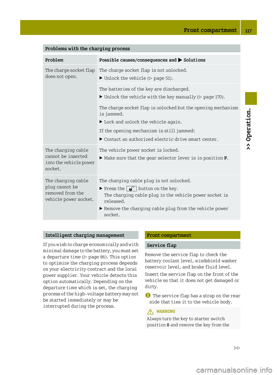
Problems with the charging process
Problem Possible causes/consequences and
0001 Solutions
The charge socke
tflap
does not open. The charge socket flap is not unlocked.
X
Unlock the vehicle (Y page 51). The batteries of the key are discharged.
X
Unlock the vehicle with the key manually (Y page 170). The charge socket flap is unlocked but the opening mechanism
is jammed.
X
Lock and unlock the vehicle again.
If the opening mechanism is still jammed:
X Contact an authorized electric drive smart center. The charging cable
cannot be inserted
into the vehicle power
socket. The vehicle power socket is locked.
X
Make sure that the gear selector lever is in position P.The charging cable
plug cannot be
removed from the
vehicle power socket. The charging cable plug is not unlocked.
X
Press the 0007button on the key.
The charging cable plug in the vehicle power socket is
released.
X Remove the charging cable plug from the vehicle power
socket. Intelligent charging management
If you wish to charge economically and with
minimal damage to the battery, you must set
a departure time (Y page 86). This option
to optimize the charging process depends
on your electricity contract and the local
power supplier. Your vehicle detects this
option automatically. Depending on the
departure time which is set, the charging
process of the high-voltage battery may not
be started immediately or may be
interrupted during the process. Front compartment
Service flap
Remove the service flap to check the
battery coolant level, windshield washer
reservoir level, and brake fluid level.
Insert the service flap on the front of the
vehicle so that it does not get damaged or
dirty.
i The service flap has a strap on the rear
side that ties it to the vehicle body. G
WARNING
Always turn the key to starter switch
position 0and remove the key from the Front compartment
117>> Operation.
Z