2013 SKODA ROOMSTER turn signal bulb
[x] Cancel search: turn signal bulbPage 23 of 219

Note■Warning messages shown in the MAXI DOT display must be confirmed with but-
ton B » Fig. 7 on page 18 to call up the main menu.■
As long as the operational faults are not rectified, the symbols are always indi-
cated again. After they are displayed for the first time, the symbols continue to be
indicated without any extra messages for the driver.
Warning lights
Introduction
This chapter contains information on the following subjects:
Handbrake
20
Brake system
20
Seat belt warning light
21
Alternator
21
Door open
21
Engine oil
21
Coolant
22
Power steering
23
Electronic Stability Control (ESC)
23
Traction Control System (ASR)
23
Anti-lock brake system (ABS)
24
Rear fog light
24
Bulb failure
24
Exhaust inspection system
24
Glow plug system (diesel engine)
24
ECU fault light (petrol engine)
25
Diesel particulate filter (diesel engine)
25
Fuel reserve
25
Airbag system
26
Tyre pressures
26
Windscreen washer fluid level
26
Traction control (TCS) switched off
26
Turn signal system
26
Low beam
27 Fog lights27 Cruise control system27
Selector lever lock
27
Main beam
27
The warning lights show certain functions/faults and may be accompanied by au-
dible signals.
WARNING■ If illuminated warning lights and the corresponding descriptions and warn-
ing notes are not observed, this may result in severe injuries or major vehicle
damage.■
The engine compartment of your car is a hazardous area. There is a risk of
injuries, scalding, accidents and fire when working in the engine compart-
ment, e.g. inspecting and replenishing oil and other fluids. It is essential to ob-
serve safety notes » page 159, Engine compartment .
Handbrake
First read and observe the introductory information and safety warn-
ings
on page 20.
The warning light
comes on if the handbrake is applied. An audible warning is
also given if you drive the vehicle for at least 3 seconds at a speed of more than
6 km/h.
The following message is shown in the MAXI DOT display.
Release parking brake!
Brake system
First read and observe the introductory information and safety warn-
ings
on page 20.
The
indicator light comes on if the brake fluid level in the braking system is too
low or there is a fault in the ABS.
The following message is shown in the MAXI DOT display. Brake fluid: Read manual.
20Operation
Page 46 of 219

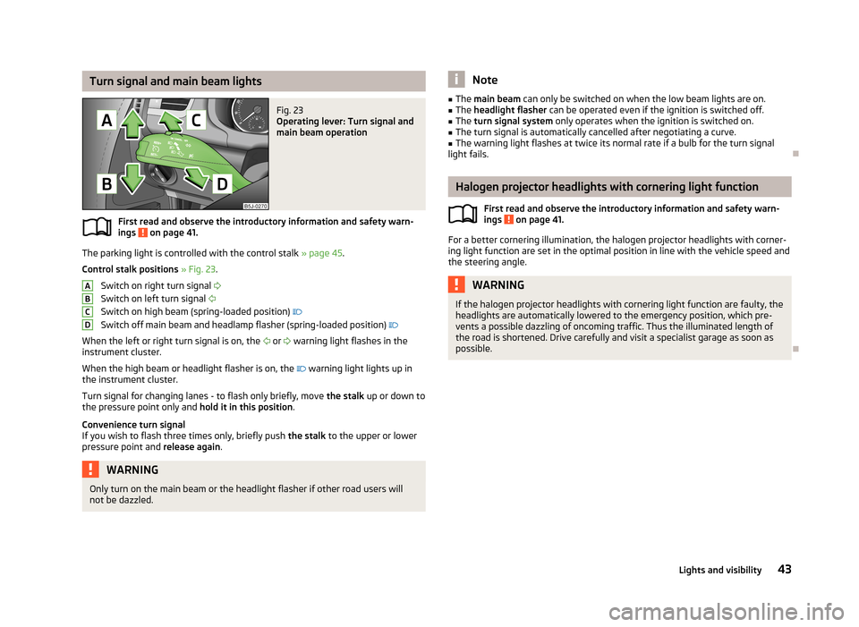
Turn signal and main beam lightsFig. 23
Operating lever: Turn signal and
main beam operation
First read and observe the introductory information and safety warn-
ings on page 41.
The parking light is controlled with the control stalk » page 45.
Control stalk positions » Fig. 23 .
Switch on right turn signal
Switch on left turn signal
Switch on high beam (spring-loaded position)
Switch off main beam and headlamp flasher (spring-loaded position)
When the left or right turn signal is on, the
or
warning light flashes in the
instrument cluster.
When the high beam or headlight flasher is on, the
warning light lights up in
the instrument cluster.
Turn signal for changing lanes - to flash only briefly, move the stalk up or down to
the pressure point only and hold it in this position.
Convenience turn signal If you wish to flash three times only, briefly push the stalk to the upper or lower
pressure point and release again.
WARNINGOnly turn on the main beam or the headlight flasher if other road users will
not be dazzled.ABCDNote■ The main beam can only be switched on when the low beam lights are on.■The headlight flasher can be operated even if the ignition is switched off.■
The turn signal system only operates when the ignition is switched on.
■
The turn signal is automatically cancelled after negotiating a curve.
■
The warning light flashes at twice its normal rate if a bulb for the turn signal
light fails.
Halogen projector headlights with cornering light function
First read and observe the introductory information and safety warn-
ings
on page 41.
For a better cornering illumination, the halogen projector headlights with corner-
ing light function are set in the optimal position in line with the vehicle speed and
the steering angle.
WARNINGIf the halogen projector headlights with cornering light function are faulty, the
headlights are automatically lowered to the emergency position, which pre- vents a possible dazzling of oncoming traffic. Thus the illuminated length of
the road is shortened. Drive carefully and visit a specialist garage as soon as possible.
43Lights and visibility
Page 196 of 219

No.Consumer32High pressure fuel pump, pressure valve33Engine control unit34Engine control unit, vacuum pump35Daytime running lights/radio for vehicles with START-STOP36Main beam37Rear fog light, DC/DC converter START-STOP38Fog lights39Air blower for heating40-41Not assigned42Rear window heater43Horn44Windscreen wipers45Central control unit for convenience system46Engine control unit, fuel pump47Cigarette lighter, power socket in the luggage compartment48ABS, START-STOP (DC/DC) converter ESP49Turn signal lights, brake lights50START-STOP (DC/DC) transformer, radio51Electrical power window (front and rear) - left side52Electrical power window (front and rear) - right side53Parking light = left side, electrical sliding/tilting roof54START-STOP (instrument cluster), alarm55Automatic gearbox control unit56Headlight cleaning system, parking light - right side57Left low beam, headlight range adjustment58Low beam on the right
Fuses in the engine compartmentFig. 155
Vehicle battery: Distribution board cover.
Fig. 156
Schematic representation of
fuse box in engine compartment
First read and observe the introductory information and safety warn-
ings on page 191.
› Press the securing clips on the fuse box cover together at the same time in the
direction of arrow
A
» Fig. 155 and remove the cover in the direction of arrow
B
.
› Release the fixtures in the openings
C
using a flat screwdriver and fold the
cover upwards in direction of arrow
D
.
Fuse assignment in engine compartment
No.Consumer1Alternator2Not assigned3Interior4Electrical auxiliary heating system 193Fuses and light bulbs
Page 197 of 219

No.Consumer5Interior6Glow plugs, radiator fan7Electrohydraulic power steering8ABS or TCS or ESC9Radiator fan10Automatic gearbox11ABS or TCS or ESC12Central control unit13Electrical auxiliary heating system
Note
Fuses 1-7 are replaced by a specialist garage.
Bulbs
Introduction
This chapter contains information on the following subjects:
Headlights
195
Changing the low beam and high beam bulb (halogen headlights)
195
Changing the high beam bulb (halogen projector headlights)
195
Changing the high beam bulb (halogen projector headlights)
196
Changing the front turn signal bulb
196
Changing the front parking light bulb
196
Fog lights and daytime running lights
196
Fog light, Roomster Scout
197
Replacing the bulb for the licence plate light
197
Tail light
198
Some manual skills are required to change a bulb. For this reason, we recommend
having bulbs replaced by a specialist garage or seeking other expert help in the
event of any uncertainties.
› Switch off the ignition and all of the lights before replacing a bulb.
› Faulty bulbs must only be replaced with the same type of bulbs. The designa-
tion is located on the light socket or the glass bulb.
› A stowage compartment for replacement bulbs is located in a plastic box in the
spare wheel or underneath the floor covering in the boot.WARNING■ Accidents can be caused if the road in front of the vehicle is not sufficiently
illuminated and the vehicle cannot or can only be seen with difficulty by other
road users.■
Always read and observe the warnings before completing any work in the
engine compartment » page 159, Engine compartment .
■
Bulbs H7 and H4 are pressurised and may burst when changed - there is a
risk of injury. We therefore recommended wearing gloves and safety glasses
when changing a bulb.
CAUTION
■ Do not take hold of the glass bulb with naked fingers (even the smallest
amount of dirt reduces the working life of the light bulb). Use a clean cloth, nap-
kin, or similar.■
When removing and installing the number plate light and tail light make sure
that the paintwork of the vehicle and the tail light are not damaged.
Note
■ This Owner's Manual only describes the replacement of bulbs where it is possi-
ble to replace the bulbs on your own without any complications arising. Other bulbs must be replaced by a specialist garage.■
We recommend that a box of replacement bulbs always be carried in the vehi-
cle. Replacement bulbs can be purchased from ŠKODAOriginal Accessories.
■
We recommend having the headlight settings checked by a specialist garage af-
ter replacing a bulb in the main or low beam.
■
Visit a specialist garage if an LED is faulty.
194Do-it-yourself
Page 198 of 219

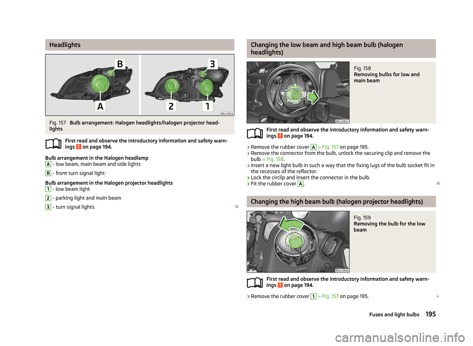
HeadlightsFig. 157
Bulb arrangement: Halogen headlights/halogen projector head-
lights
First read and observe the introductory information and safety warn-ings
on page 194.
Bulb arrangement in the Halogen headlamp
A
- low beam, main beam and side lights
B
- front turn signal light
Bulb arrangement in the Halogen projector headlights
1
- low beam light
2
- parking light and main beam
3
- turn signal lights
Changing the low beam and high beam bulb (halogen
headlights)Fig. 158
Removing bulbs for low and
main beam
First read and observe the introductory information and safety warn-
ings on page 194.
›
Remove the rubber cover
A
» Fig. 157 on page 195.
›
Remove the connector from the bulb, unlock the securing clip and remove the
bulb » Fig. 158 .
›
Insert a new light bulb in such a way that the fixing lugs of the bulb socket fit in
the recesses of the reflector.
›
Lock the circlip and insert the connector in the bulb.
›
Fit the rubber cover
A
.
Changing the high beam bulb (halogen projector headlights)
Fig. 159
Removing the bulb for the low
beam
First read and observe the introductory information and safety warn-
ings on page 194.
›
Remove the rubber cover
1
» Fig. 157 on page 195.
195Fuses and light bulbs
Page 199 of 219

›Turn the socket with the bulb to the stop in the direction of the arrow
» Fig. 159
and remove it.›
Replace the bulb, insert the connector and new bulb and turn to the stop in the
opposite direction to that of the arrow.
›
Fit the rubber cover
1
.
Changing the high beam bulb (halogen projector headlights)
Fig. 160
Removing the bulb for the main
beam
First read and observe the introductory information and safety warn-
ings on page 194.
›
Remove the rubber cover
2
» Fig. 157 on page 195.
›
Turn the socket with the bulb to the stop in the direction of the arrow » Fig. 160
and remove it.
›
Replace the bulb, insert the connector and new bulb and turn to the stop in the
opposite direction to that of the arrow.
›
Fit the rubber cover
2
.
Changing the front turn signal bulb
First read and observe the introductory information and safety warn-ings
on page 194.
›
Remove the bulb holder
B
» Fig. 157 on page 195 or the bulb holder
3
to the
stop in an anti-clockwise direction and remove with the bulb for the turn signal.
›
Replace the bulb, insert the bulb holder with the new bulb and turn clockwise
to the stop.
Changing the front parking light bulb
First read and observe the introductory information and safety warn-
ings
on page 194.
›
Remove rubber cover
A
» Fig. 157 on page 195 or
2
.
›
Grasp the lamp holder and remove it from the bulb housing.
›
Replace the light bulb and insert the lamp holder back into the headlamp with
the bulb.
›
Fit the rubber cover.
Fog lights and daytime running lights
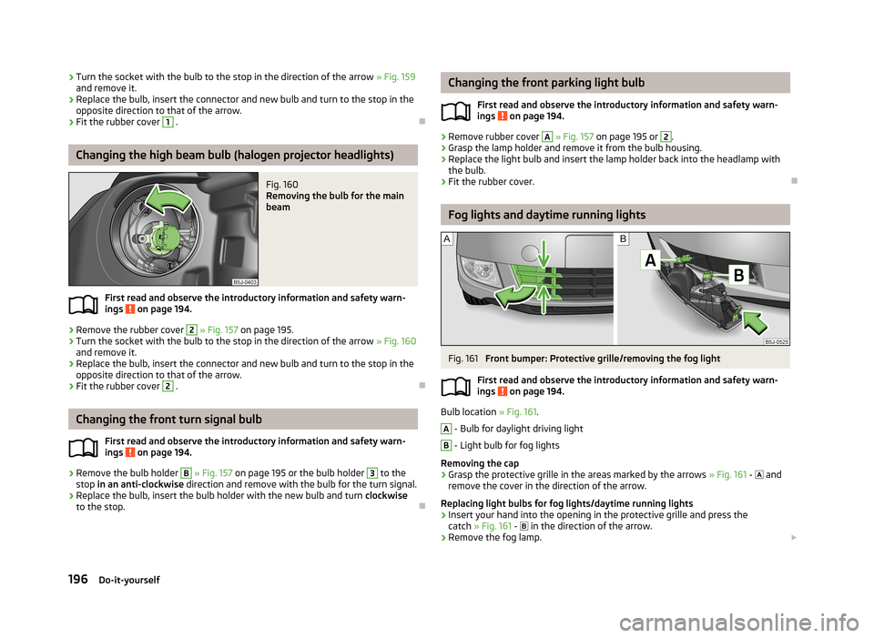
Fig. 161
Front bumper: Protective grille/removing the fog light
First read and observe the introductory information and safety warn-
ings
on page 194.
Bulb location » Fig. 161.
A
- Bulb for daylight driving light
B
- Light bulb for fog lights
Removing the cap
›
Grasp the protective grille in the areas marked by the arrows » Fig. 161 -
and
remove the cover in the direction of the arrow.
Replacing light bulbs for fog lights/daytime running lights
›
Insert your hand into the opening in the protective grille and press the catch » Fig. 161 -
in the direction of the arrow.
›
Remove the fog lamp.
196Do-it-yourself
Page 201 of 219

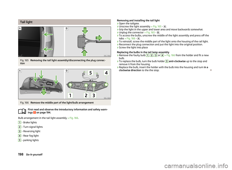
Tail lightFig. 165
Removing the tail light assembly/disconnecting the plug connec-
tion
Fig. 166
Remove the middle part of the light/bulb arrangement
First read and observe the introductory information and safety warn- ings
on page 194.
Bulb arrangement in the tail light assembly » Fig. 166.
1
- Brake lights
2
- Turn signal lights
3
- Reversing light
4
- Rear fog light
5
- parking lights
Removing and installing the tail light›Open the tailgate.›
Unscrew the light assembly » Fig. 165 - .
›
Grip the light in the upper and lower area and move backwards somewhat.
›
Unplug the connector » Fig. 165 - .
›
To access the bulbs, unscrew the middle of the light assembly and press off the
tabs » Fig. 166 - .
›
To reinstall, screw the middle part of the light onto the housing of the rail light.
›
Reconnect the plug connection and put the light into the original position.
›
Screw the light into place
Replacing the bulbs in the tail lamp assembly
›
Remove the faulty bulb
1
,
2
,
3
or
4
» Fig. 166 from the holder and fit a new
bulb.
›
To replace the bulb, turn the bulb holder
5
anti-clockwise up to the stop and
remove it from the housing.
›
Replace the bulb, insert the holder with the bulb into the housing and turn in a
clockwise direction to the the stop.
198Do-it-yourself
Page 210 of 219

Central locking system31
lock33
unlock33
Changing Brake fluid
168
Changing the bulb for fog light (Scout)197
Engine oil165
Fog lights and daytime running lights bulbs196
Front parking light bulb196
Front turn signal bulb196
High beam bulb - halogen projector headlights 195, 196
Low beam and high beam bulb - halogen head- lights
195
Wheels180
Changing a wheel Follow-up work
182
Preliminary work181
Remove and attaching a wheel181
Charging a vehicle battery170
Check Fit ball head properly
119
Checking Battery electrolyte level
170
Brake fluid167
Coolant166
Engine oil164
Oil level164
Windscreen washer fluid162
Children and safety139
Child safety Side airbag
140
Child safety lock29
Child seat Classification
141
ISOFIX141
on the front passenger seat140
TOP TETHER143
Use of child seats141
Use of ISOFIX child seats142
Chrome parts refer to Taking care of your vehicle
152
Cigarette lighter67
Cleaning144
Alcantara155
Covers of electrically heated seats156
Fabrics155
Headlight lenses153
Natural leather155
Plastic parts151
Synthetic leather155
Wheels153
Climatronic83
automatic mode84
Control elements83
Controlling blower85
Defrosting windscreen85
Recirculated air mode84
Setting the temperature84
Clock12
Clothes hook68
Cockpit 12-volt power outlet
67
Ashtray66
Cigarette lighter67
General view9
Lighting46
Storage compartments68
Compartments68
Computer see Multifunction display
13
Convenience turn signal43
Coolant165
Checking166
Display messages22
Replenishing167
Warning light22
Coolant temperature gauge display
11
Correct seated position124
Driver125
Front passenger125
Instructions125
Rear seats125
Counter for distance driven12
Cruise Control System113
Cupholders66
D
DAY LIGHT see Daylight running lights
42
Daylight running lights42
Deactivating an airbag137
Decorative films152
Defrosting rear window47
Delayed locking of the boot lid see Boot lid
37
Diesel refer to Fuel
159
Diesel fuel Operation in winter
159
Diesel particulate filter25
display messages25
Digital clock12
Dipstick164
Display Service interval
16
Distance driven12
Door Child safety lock
29
Closing30
Door open warning light21
Opening30
Doors Emergency locking
31
Driving Abroad
109
Driving through water on streets108
Emissions199
Fuel consumption199
Maximum speed202
207Index