2013 SKODA ROOMSTER seat adjustment
[x] Cancel search: seat adjustmentPage 12 of 219

Operation
Cockpit
OverviewDoor handle
30
Electrical power windows
38
Electric exterior mirror adjustment
51
Air outlet vents
77
Car park ticket holder
68
Operating lever:
› Turn signal light, headlight and parking light, headlight flasher
43
›
Speed regulating system
113
Steering wheel:
› With horn
› With driver’s front airbag
134
›With pushbuttons for radio, navigation system and mobile
phone
86
Instrument cluster: Instruments and warning lights
10
Operating lever:
› Windscreen wiper and wash system
49
›Multifunction display
13
›
MAXI DOT display
18
Button for rear window heater
47
TCS switch
111
Air outlet vents in the central part of the instrument panel
77
Button for hazard warning light system
45
Warning light for the deactivated front seat passenger airbag
137
Depending on equipment fitted:
› Operating controls for the heating
78
›Operating controls for the air conditioning system
80
›Operating controls for Climatronic
83
Storage compartments on the front passenger side
69
Front passenger airbag
134
Air outlet vents
77123456789101112131415161718Key-operated switch for the front seat passenger airbag137Door handle30
Switch depending on equipment fitted:
› Boot lid remote release
37
›Interior monitor
36
Light switch and headlamp beam adjustment
41, 42
Fuse box in the dashboard
192
Bonnet release lever
161
Lever for adjusting the steering wheel
95
Ignition lock
97
Pedals
100
Depending on equipment fitted:
› Gear lever (manual gearbox)
99
›Selector lever (automatic gearbox)
101
Rocker switch for front left seat heating
53
Central locking system
33
Handbrake
99
Rocker switch for front right seat heating
53
Depending on equipment fitted:
› Ashtrays
66
›Storage compartment
71
Depending on equipment fitted:
› Radio
› Navigation system
MDI
94
Note
The arrangement of the controls right-hand drive models may differ from the lay-
out shown in » Fig. 1. The symbols on the controls and switches are the same as
for left-hand drive models.19202122232425262728293031323334359Cockpit
Page 45 of 219

Headlight beam adjustmentFig. 22
Dash panel: Lights and visibility
First read and observe the introductory information and safety warn-
ings on page 41.
Turning the rotary switch » Fig. 22 from position
to
gradually adjusts the
headlight beam thereby shortening the beam of light.
The positions of the rotary switch correspond approximately to the following
car load.
Front seats occupied, boot empty.
All seats occupied, boot empty.
All seats occupied, boot loaded.
Driver seat occupied, boot loaded.
WARNINGAlways adjust the headlight beam to satisfy the following conditions.■The vehicle does not dazzle other road users, especially oncoming vehicles.■
The beam range is sufficient for safe driving.
Note
We recommend you adjust the headlight beam when the low beam is switched
on.
Daylight running lights (DAY LIGHT)
First read and observe the introductory information and safety warn-
ings
on page 41.
Switching on daytime running lights
›
Turn the light switch to position 0 » Fig. 21 on page 41.
Activating/deactivating the daytime running lights function
›
Activate and deactivate the daytime running lights by fitting/removing the fuse
with the appropriate ampere rating for daytime running lights » page 192,
Fuses in the dash panel .
Deactivating on vehicles with the START-STOP system
›
Switch off the ignition.
›
At the same time, pull the turn signal light stalk » Fig. 23 on page 43 towards
the steering wheel, push it downwards, and hold it in this position.
›
Switch on the ignition - wait until the left-turn signal light flashes 4x.
›
Switch off the ignition - an audible signal sounds which confirms the deactiva- tion of the daylight driving lights.
›
Release the turn signal stalk.
Activating on vehicles with the START-STOP system
›
Switch off the ignition.
›
At the same time, pull the turn signal light stalk » Fig. 23 on page 43 towards
the steering wheel, push it upwards, and hold it in this position.
›
Switch on the ignition - wait until the right-turn signal light flashes 4x.
›
Switch off the ignition - an audible signal sounds which confirms the activation
of the daylight driving lights.
›
Release the turn signal stalk.
On vehicles with separate lights for daylight driving lights in the fog lights or in
the front bumper, the parking lights and the licence plate light do not come on
when activating the function daylight driving lights (neither front nor rear).
If the vehicle is not equipped with separate lights for daylight driving lights, the
combination of the low beam, the parking lights (front and rear) including the li-
cence plate light is used as daylight driving lights.
Note
The daytime driving lights also serve as parking lights on vehicles with separate
lights for daylight driving lights (in the bumper below the main headlights).
42Operation
Page 55 of 219
Seats and stowing
Front seats
Introduction
This chapter contains information on the following subjects:
Adjusting the front seats
53
Front seat heating
53
The driver's seat should be adjusted in such a way that the pedals can be fully
pressed to the floor with slightly bent legs.
The seat backrest on the driver's seat should be adjusted in such a way that the
upper point of the steering wheel can be easily reached with slightly bent arms.
Correct adjustment of the seats is particularly important:
› for safely and quickly reaching the controls;
› for a relaxed body position that reduces fatigue;
› for achieving maximum protection from the seat belts and the airbag system.
WARNINGGeneral information■Caution when adjusting the seat! You may suffer injuries or bruises as a re-
sult of adjusting the seat without paying proper attention.■
The seat backrests must not be tilted too far back when driving, as this will
impair the function of the seat belts and of the airbag system – risk of injury!
■
Never carry more people than the number of seats in the vehicle.
■
Each occupant must correctly fasten the seat belt belonging to the seat.
Children must be fastened » page 139, Transporting children safely with a
suitable restraint system.
■
The front seats and head restraints must be adjusted to match the body
size at all times and the seat belt must always be fastened properly to provide
the most effective levels of protection to the passengers.
■
Do not carry any objects on the front passenger seat except objects de-
signed for this purpose (e.g. child seat) – risk of accident!
WARNINGInformation for the driver■Only adjust the driver's seat when the vehicle is stationary – risk of accident!■
Maintain a distance of at least 25 cm to the steering wheel. Not maintaining
this minimum distance will mean that the airbag system will not be able to
properly protect you – hazard!
■
Ensure that there are no objects in the driver's footwell, as these may get
caught in the pedal apparatus when driving or braking. You would then no
longer be able to operate the clutch, brake or acceleration pedals.
WARNINGInformation for the front seat passenger■Maintain a distance of at least 25 cm from the dash panel. Not maintaining
this minimum distance will mean that the airbag system will not be able to
properly protect you - there is a risk that you could be killed.■
Always keep your feet in the footwell when the car is being driven - never
place your feet on the instrument panel, out of the window or on the seats.
You will be exposed to increased risk of injury if it becomes necessary to apply
the brakes or in the event of an accident. You may suffer fatal injuries when
an airbag is deployed if you have adopted an incorrect seating position.
Note
After a certain time, play can develop within the adjustment mechanism of the
backrest angle.
52Operation
Page 76 of 219
stowage compartments in the luggageFig. 72
Storage compartments in the
side trim panel
First read and observe the introductory information and safety warn-
ings on page 68.
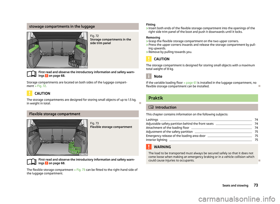
Storage compartments are located on both sides of the luggage compart-
ment » Fig. 72 .
CAUTION
The storage compartments are designed for storing small objects of up to 1.5 kg.
in weight in total.
Flexible storage compartment
Fig. 73
Flexible storage compartment
First read and observe the introductory information and safety warn-
ings on page 68.
The flexible storage compartment » Fig. 73 can be fitted to the right-hand side of
the luggage compartment.
Fitting›Insert both ends of the flexible storage compartment into the openings of the
right side trim panel of the boot and push it downwards until it locks.
Removing›
Grasp the flexible storage compartment on the two upper corners.
›
Press the upper corners inwards and release the storage compartment by pull-
ing upwards.
›
Remove by pulling towards you.
CAUTION
The storage compartment is designed for storing small objects with a maximum
total weight of 8 kg.
Note
If the variable loading floor » page 61 is installed in the luggage compartment, no
flexible storage compartment can be installed.
Praktik
Introduction
This chapter contains information on the following subjects:
Lashings
74
Adjustable safety partition behind the front seats
74
Attachment of the loading floor
74
Adjustment of the safety partition
75
Emergency release of the loading area door
75
Interior lighting
75WARNINGThe load to be transported must always be secured safely so that it does not
come loose when making an emergency braking or in a vehicle collision which
could cause injuries to occupants.
73Seats and stowing
Page 78 of 219
Adjustment of the safety partitionFig. 77
Top/lower support of the safety partition
First read and observe the introductory information and safety warn-
ings
on page 73.
Only valid for some countries.
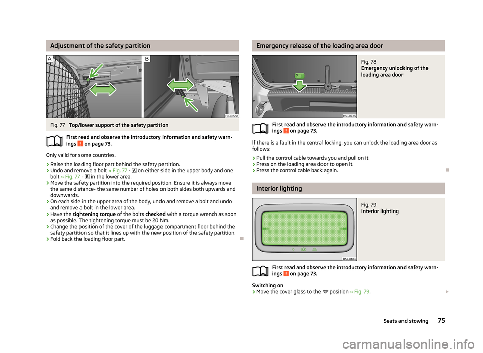
›
Raise the loading floor part behind the safety partition.
›
Undo and remove a bolt » Fig. 77 -
on either side in the upper body and one
bolt » Fig. 77 -
in the lower area.
›
Move the safety partition into the required position. Ensure it is always move
the same distance- the same number of holes on both sides both upwards anddownwards.
›
On each side in the upper area of the body, undo and remove a bolt and undoand remove a bolt in the lower area.
›
Have the tightening torque of the bolts checked with a torque wrench as soon
as possible. The tightening torque must be 20 Nm.
›
Change the position of the cover of the luggage compartment floor behind the safety partition so that it lines up with the new position of the safety partition.
›
Fold back the loading floor part.
Emergency release of the loading area doorFig. 78
Emergency unlocking of the
loading area door
First read and observe the introductory information and safety warn-
ings on page 73.
If there is a fault in the central locking, you can unlock the loading area door as
follows:
›
Pull the control cable towards you and pull on it.
›
Press on the loading area door to open it.
›
Press the control cable back again.
Interior lighting
Fig. 79
Interior lighting
First read and observe the introductory information and safety warn- ings on page 73.
Switching on
›
Move the cover glass to the position
» Fig. 79.
75Seats and stowing
Page 128 of 219
Correct seated position for the driverFig. 109
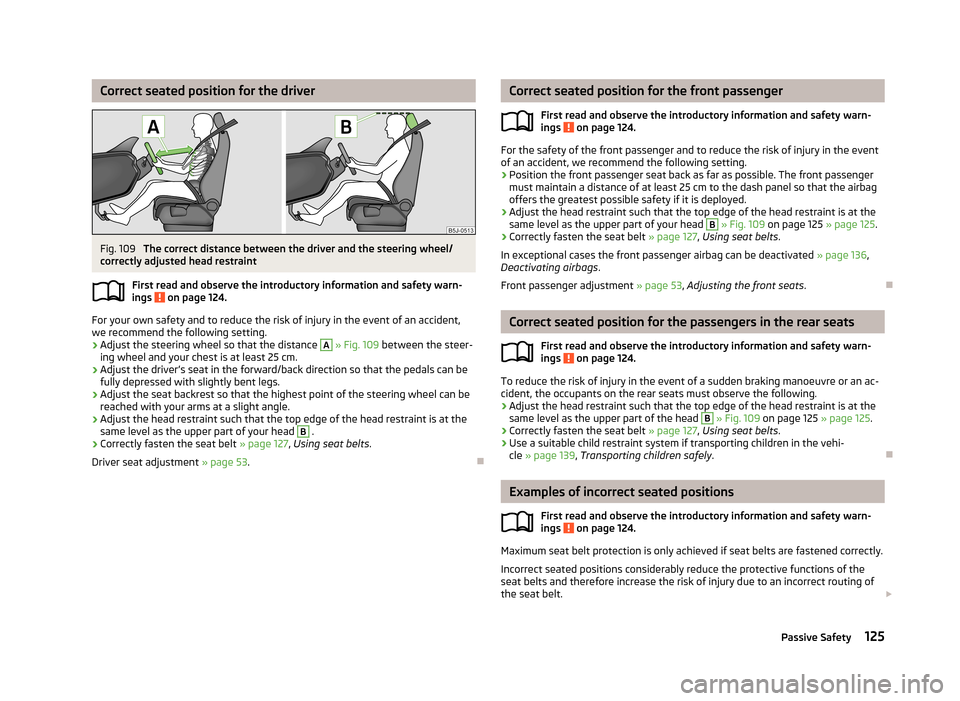
The correct distance between the driver and the steering wheel/
correctly adjusted head restraint
First read and observe the introductory information and safety warn-ings
on page 124.
For your own safety and to reduce the risk of injury in the event of an accident,
we recommend the following setting.
› Adjust the steering wheel so that the distance
A
» Fig. 109 between the steer-
ing wheel and your chest is at least 25 cm.
› Adjust the driver’s seat in the forward/back direction so that the pedals can be
fully depressed with slightly bent legs.
› Adjust the seat backrest so that the highest point of the steering wheel can be
reached with your arms at a slight angle.
› Adjust the head restraint such that the top edge of the head restraint is at the
same level as the upper part of your head
B
.
› Correctly fasten the seat belt
» page 127, Using seat belts .
Driver seat adjustment » page 53.
Correct seated position for the front passenger
First read and observe the introductory information and safety warn-ings
on page 124.
For the safety of the front passenger and to reduce the risk of injury in the event
of an accident, we recommend the following setting.
› Position the front passenger seat back as far as possible. The front passenger
must maintain a distance of at least 25 cm to the dash panel so that the airbag
offers the greatest possible safety if it is deployed.
› Adjust the head restraint such that the top edge of the head restraint is at the
same level as the upper part of your head
B
» Fig. 109 on page 125 » page 125.
› Correctly fasten the seat belt
» page 127, Using seat belts .
In exceptional cases the front passenger airbag can be deactivated » page 136,
Deactivating airbags .
Front passenger adjustment » page 53, Adjusting the front seats .
Correct seated position for the passengers in the rear seats
First read and observe the introductory information and safety warn-
ings
on page 124.
To reduce the risk of injury in the event of a sudden braking manoeuvre or an ac-
cident, the occupants on the rear seats must observe the following.
› Adjust the head restraint such that the top edge of the head restraint is at the
same level as the upper part of the head
B
» Fig. 109 on page 125 » page 125.
› Correctly fasten the seat belt
» page 127, Using seat belts .
› Use a suitable child restraint system if transporting children in the vehi-
cle » page 139 , Transporting children safely .
Examples of incorrect seated positions
First read and observe the introductory information and safety warn-
ings
on page 124.
Maximum seat belt protection is only achieved if seat belts are fastened correctly.
Incorrect seated positions considerably reduce the protective functions of the
seat belts and therefore increase the risk of injury due to an incorrect routing of
the seat belt.
125Passive Safety
Page 195 of 219

Fuses in the dash panelFig. 153
Underside of the dash panel:
Distribution board cover.
Fig. 154
Schematic representation of the fuse box for vehicles with left-
hand steering/right-hand steering
First read and observe the introductory information and safety warn-
ings
on page 191.
The fuses are located on the left side of the dash panel behind a cover.
› Carefully remove the cover in the direction of the arrow
» Fig. 153.
› After the fuse has been replaced, replace the cover in the dash panel in the op-
posite direction of the arrow so that the guide lugs are guided into the open- ings of the dash panel. Close the cover until it clicks into place.
Fuse assignment in the dash panel
No.Consumer1S-contact2START-STOP, air-conditioning system3Instrument cluster, headlamp beam adjustmentNo.Consumer4Control unit for ABS, button for START STOP5Petrol engine: Speed regulating system6Reversing light (manual gearbox)7Ignition, engine control unit, automatic gearbox8Brake pedal switch, clutch pedal switch9Operating controls for the heating, control unit for air conditioning sys-
tem, parking aid, control unit for cornering lights, radiator fan, washing nozzles10Windscreen Wiper and Washer System11Mirror adjustment12Control unit for trailer detection13Automatic gearbox control unit14Motor for halogen projector headlights with cornering light function15PDA navigation system16Electrohydraulic power steering17Light switch power supply18Mirror heater19S-contact20Alarm21Reversing light, fog lights with the function CORNER22Operating controls for the heating, control unit for air conditioning sys-
tem, parking aid, mobile phone, instrument cluster, steering angle
sender, ESC, vehicle voltage control unit, multifunction steering wheel23Interior lighting, storage compartment and luggage compartment, side
lights24Central control unit25Seat heaters26Rear window wiper27Telephone preinstallation28Petrol engine: AKF valve, Diesel engine: Control flap29Injection, coolant pump30Fuel pump, ignition, Cruise control system, operation of PTC relay31Lambda probe 192Do-it-yourself
Page 212 of 219

HeatingDeicing the windows79
Exterior mirrors51
Operating78
Operation79
Rear window47
Recirculated air mode80
Seats53
Heating and air-conditioning77
Hill hold control110
Horn9
I
Ignition
97
Ignition lock97
Immobilizer97
Individual settings locking
32
unlocking32
Inertia reels130
Instrument cluster10
Overview10
Interior monitor36
Internal lighting Praktik
75
Internal lights Praktik
75
ISOFIX141
J
Jack
180
Jacking points Raise vehicle
183
Jump-starting186, 187
L
lashings Praktik
74
LightCockpit46
Headlight beam adjustment42
Headlight flash43
Replacing bulbs194
Lights41
Cockpit46
Daylight running42
Fog lights44
Foglights with the CORNER function44
Halogen projector headlights with cornering light
function
43
Hazard warning light system45
Low beam lights41
Main beam lights43
Parking lights41, 45
Rear fog light44
Switching on and off41
Tourist lights44
Turn signals43
warning lights20
Loads199
Lock Central locking system
33
Locking Emergency locking
31
Remote control34
without central locking30
Locking and unlocking from the inside33
Low beam lights41
Luggage compartment Class N1 vehicles
58
Lighting47
Variable loading floor61
Luggage compartment lid37
M
Main beam
43
Maintenance107
Decorative films152
Manual air conditioning Recirculated air mode82
Manual gear changing see gear changing
99
Materials defect liability5
MAXI DOT Main menu
18
see MAXI DOT display18
Settings18
MAXI DOT display18
Maximum speed202
MDI94
Mirror Exterior mirrors
51
Manually dimmed rear-view mirror51
Vanity48
Mobile phone86
Connecting to the hands-free system89
Modes of the automatic transmission101
Modifications146
Modifications and technical alterations Airbags
148
Service147
Spoiler148
Multifunction display Functions
13
Memory14
Operation14
Multimedia92
N
N1
58
Net partition60
O
Oil See Engine oil
164
Oil pressure Display messages
21
209Index