2013 SKODA ROOMSTER window
[x] Cancel search: windowPage 54 of 219
Rear window
Introduction
This chapter contains information on the following subjects:
Manually dimmed rear-view mirror
51
Exterior mirrors
51WARNING■ Make sure that the mirror is not covered by ice, snow, condensation or other
objects.■
Convex (curved outward) or aspheric exterior mirrors increase the field of vi-
sion. They do, however, make objects appear smaller in the mirror. These mir-
rors are therefore only of limited use for estimating distances to the following vehicles.
■
Whenever possible use the interior mirror for estimating the distances to
the following vehicles.
Manually dimmed rear-view mirror
First read and observe the introductory information and safety warn-ings
on page 51.
Basic setting
›
Pull the lever on the lower edge of the mirror away from the windscreen.
Dimming mirror
›
Push the lever on the lower edge of the mirror towards the windscreen.
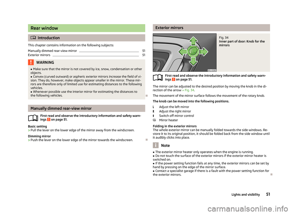
Exterior mirrorsFig. 34
Inner part of door: Knob for the
mirrors
First read and observe the introductory information and safety warn-
ings on page 51.
The mirror can be adjusted to the desired position by moving the knob in the di-
rection of the arrow » Fig. 34.
The movement of the mirror surface follows the movement of the rotary knob.
The knob can be moved into the following positions.
Adjust the left mirror
Adjust the right mirror
Switch off mirror control
Mirror heater
Folding in the exterior mirrors
The whole exterior mirror can be manually folded towards the side windows. Re- store it to its original position, it should be folded back from the side window until
it audibly clicks into place.
Note
■ The exterior mirror heater only operates when the engine is running.■Do not touch the surface of the exterior mirrors if the exterior mirror heater is
switched on.■
If the power setting function fails at any time, the exterior mirrors can be set by
hand by pressing on the edge of the mirror surface.
■
Contact a specialist garage if there is a fault with the power setting function for
the exterior mirrors.
51Lights and visibility
Page 55 of 219
Seats and stowing
Front seats
Introduction
This chapter contains information on the following subjects:
Adjusting the front seats
53
Front seat heating
53
The driver's seat should be adjusted in such a way that the pedals can be fully
pressed to the floor with slightly bent legs.
The seat backrest on the driver's seat should be adjusted in such a way that the
upper point of the steering wheel can be easily reached with slightly bent arms.
Correct adjustment of the seats is particularly important:
› for safely and quickly reaching the controls;
› for a relaxed body position that reduces fatigue;
› for achieving maximum protection from the seat belts and the airbag system.
WARNINGGeneral information■Caution when adjusting the seat! You may suffer injuries or bruises as a re-
sult of adjusting the seat without paying proper attention.■
The seat backrests must not be tilted too far back when driving, as this will
impair the function of the seat belts and of the airbag system – risk of injury!
■
Never carry more people than the number of seats in the vehicle.
■
Each occupant must correctly fasten the seat belt belonging to the seat.
Children must be fastened » page 139, Transporting children safely with a
suitable restraint system.
■
The front seats and head restraints must be adjusted to match the body
size at all times and the seat belt must always be fastened properly to provide
the most effective levels of protection to the passengers.
■
Do not carry any objects on the front passenger seat except objects de-
signed for this purpose (e.g. child seat) – risk of accident!
WARNINGInformation for the driver■Only adjust the driver's seat when the vehicle is stationary – risk of accident!■
Maintain a distance of at least 25 cm to the steering wheel. Not maintaining
this minimum distance will mean that the airbag system will not be able to
properly protect you – hazard!
■
Ensure that there are no objects in the driver's footwell, as these may get
caught in the pedal apparatus when driving or braking. You would then no
longer be able to operate the clutch, brake or acceleration pedals.
WARNINGInformation for the front seat passenger■Maintain a distance of at least 25 cm from the dash panel. Not maintaining
this minimum distance will mean that the airbag system will not be able to
properly protect you - there is a risk that you could be killed.■
Always keep your feet in the footwell when the car is being driven - never
place your feet on the instrument panel, out of the window or on the seats.
You will be exposed to increased risk of injury if it becomes necessary to apply
the brakes or in the event of an accident. You may suffer fatal injuries when
an airbag is deployed if you have adopted an incorrect seating position.
Note
After a certain time, play can develop within the adjustment mechanism of the
backrest angle.
52Operation
Page 61 of 219
WARNING (Continued)■Please note that transporting heavy objects alters the handling properties
of the vehicle due to the displacement of the centre of gravity – risk of acci-
dent! The speed and style of driving must be adjusted accordingly.■
If the items of luggage or objects are attached to the lashing eyes with un-
suitable or damaged lashing straps, injuries can occur in the event of braking
manoeuvres or accidents. To prevent items of luggage from being thrown for-
ward, always use suitable lashing straps which must be firmly attached to the lashing eyes.
■
The transported items must be stowed in such a way that no objects are
able to slip forward on sudden driving or braking manoeuvres – risk of injury!
■
When transporting fastened objects which are sharp and dangerous in the
boot that has been enlarged by folding the rear seats forward, ensure the safety of the passengers transported on the other rear seats » page 125, Cor-
rect seated position for the passengers in the rear seats .
■
If the rear seat next to the folded forward seat is occupied, ensure maxi-
mum safety, e.g. by placing the goods to be transported in such a way that the
seat is prevented from folding back in case of a rear collision.
■
Never drive with the luggage compartment lid open or ajar, as otherwise ex-
haust gases may get into the interior of the vehicle – risk of poisoning!
■
Under no circumstances should the permissible axle loads and the permissi-
ble total vehicle weight be exceeded – risk of accident!
■
Never transport people in the boot!
CAUTION
Please ensure that the heating elements for the rear window heater are not dam-
aged as a result of abrasive objects.
Note
Tyre pressure must be adjusted to the load » page 173, Service life of tyres .
Class N1 vehicles
First read and observe the introductory information and safety warn-
ings
on page 57.
On class N1 vehicles, which are not fitted with a protective grille, a lashing set which complies with the standard EN 12195 (1 - 4) must be used for fastening the
load.
The proper functioning of the electrical system is essential for the safe operation
of the vehicle. It is important to ensure that it is not damaged during modifica-
tions or when loading or unloading the luggage compartment.
Fastening elements
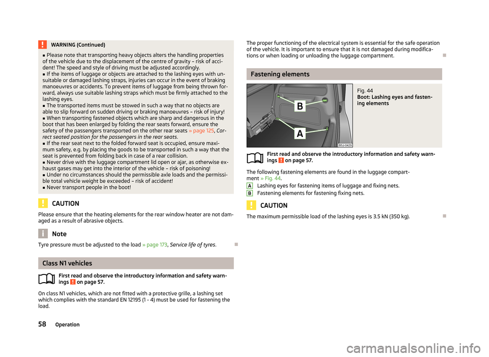
Fig. 44
Boot: Lashing eyes and fasten-
ing elements
First read and observe the introductory information and safety warn-
ings on page 57.
The following fastening elements are found in the luggage compart-
ment » Fig. 44 .
Lashing eyes for fastening items of luggage and fixing nets.
Fastening elements for fastening fixing nets.
CAUTION
The maximum permissible load of the lashing eyes is 3.5 kN (350 kg).
AB58Operation
Page 63 of 219
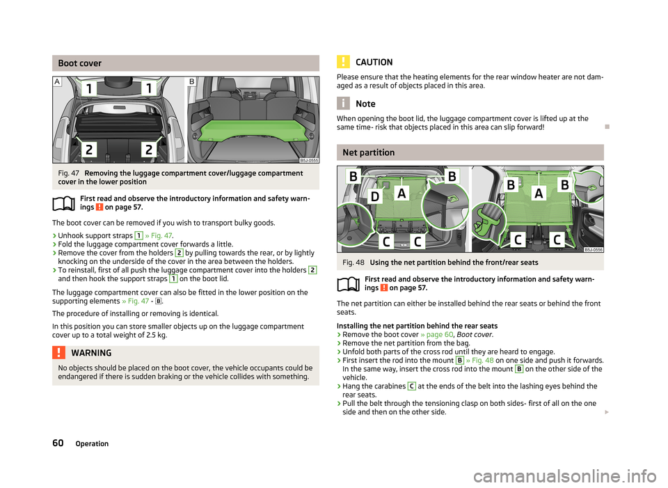
Boot coverFig. 47
Removing the luggage compartment cover/luggage compartment
cover in the lower position
First read and observe the introductory information and safety warn-
ings
on page 57.
The boot cover can be removed if you wish to transport bulky goods.
›
Unhook support straps
1
» Fig. 47 .
›
Fold the luggage compartment cover forwards a little.
›
Remove the cover from the holders
2
by pulling towards the rear, or by lightly
knocking on the underside of the cover in the area between the holders.
›
To reinstall, first of all push the luggage compartment cover into the holders
2
and then hook the support straps
1
on the boot lid.
The luggage compartment cover can also be fitted in the lower position on the
supporting elements » Fig. 47 -
.
The procedure of installing or removing is identical. In this position you can store smaller objects up on the luggage compartment cover up to a total weight of 2.5 kg.
WARNINGNo objects should be placed on the boot cover, the vehicle occupants could be
endangered if there is sudden braking or the vehicle collides with something.CAUTIONPlease ensure that the heating elements for the rear window heater are not dam-
aged as a result of objects placed in this area.
Note
When opening the boot lid, the luggage compartment cover is lifted up at the
same time- risk that objects placed in this area can slip forward!
Net partition
Fig. 48
Using the net partition behind the front/rear seats
First read and observe the introductory information and safety warn-
ings
on page 57.
The net partition can either be installed behind the rear seats or behind the front
seats.
Installing the net partition behind the rear seats
›
Remove the boot cover » page 60, Boot cover .
›
Remove the net partition from the bag.
›
Unfold both parts of the cross rod until they are heard to engage.
›
First insert the rod into the mount
B
» Fig. 48 on one side and push it forwards.
In the same way, insert the cross rod into the mount
B
on the other side of the
vehicle.
›
Hang the carabines
C
at the ends of the belt into the lashing eyes behind the
rear seats.
›
Pull the belt through the tensioning clasp on both sides- first of all on the one side and then on the other side.
60Operation
Page 67 of 219

Install bicycle carrierFig. 54
Install bicycle carrier
First read and observe the introductory information and safety warn-ings on page 63.
›
Position the approved bicycle carrier on the cross member.
›
Remove bolt
A
» Fig. 54 a little and push the frame side rail (aluminium part)
towards the cross member until the socket latches.
›
Insert the screw
A
into the nut.
›
Undo the screw
B
on the movable part of the bicycle carrier and unscrew.
›
Place the movable part of the fixture, depending on the size of the vehicle, in
one of the possible positions so that the bicycle does not touch the boot lid. We
recommend to place the moveable part of the fixture in such a position that 7 holes are visible between the screw
A
and the moveable part.
›
Insert the screw
B
into the desired position and tighten.
Put bicycle into the bicycle carrier
Fig. 55
Put in the bicycle/example fastening the front wheel
First read and observe the introductory information and safety warn-
ings on page 63.›
Remove the front wheel of the bicycle before installing it.
›
Slacken the quick tension jack on the fixing axle of the bicycle carrier and adjust
according to the width of the bicycle fork.
›
Place the bicycle fork on the fixing axle and tighten with the quick release lev- er » Fig. 55 - .
›
Position the left pedal of the bicycle forward, in order to attach the front wheel
more easily.
›
Undo the bolt
A
» Fig. 54 on page 64 and push the bicycle carrier to the left
together with the mounted bicycle to prevent a collision between the handle-
bars and the side window of the luggage compartment.
›
Carefully guide the boot lid downwards without letting go of it. Check whether there is sufficient room between the steering bars and the rear window. If nec-essary, adjust the position of the movable part of the bicycle carrier to prevent a
collision » page 64 .
›
It is best to store the removed front wheel between the left crank and the bicy-
cle frame, attach it with a strap to the front fork » Fig. 55 -
or to one of the
fixing points.
›
The second carrier is installed and the bicycle is secured in a similar way.
Secure the stability of the bicycles with a belt
Fig. 56
Securing bicycles
First read and observe the introductory information and safety warn- ings
on page 63.
›
To slacken the rubber part of the clamp, push both parts against each other and
open the clamp.
64Operation
Page 80 of 219

Heating and air-conditioning
Heating, ventilation, cooling
Introduction
This chapter contains information on the following subjects:
Air outlets
77
Using the air conditioning system economically
78
Operational problems
78
The heating effect is dependent upon the coolant temperature, thus full heat
output only occurs when the engine has reached its operating temperature.
If the cooling system is switched on, the temperature and air humidity drops in
the vehicle. The cooling system prevents the windows from misting up when out- side temperatures are particularly low.
It is possible to briefly activate recirculated air mode to enhance the cooling ef- fect.
Please refer to the information regarding recirculated air mode for the air-condi- tioning system » page 82 or for Climatronic » page 84.
WARNINGFor your own safety and that of other road users, ensure that all the windows
are free of ice, snow and misting. Please familiarize yourself about how to cor- rectly operate the heating and ventilation systems, how to demist and defrost
the windows, as well as with the cooling mode.
CAUTION
■ The air inlet in front of the windscreen must be free (e.g. of ice, snow or leaves)
to ensure that the heating and cooling system operates properly.■
After switching on the cooling Condensation from the evaporator of the air con-
ditioning may drip down and form a puddle below the vehicle. This is not a leak.
Note■ The exhaust air streams out through vents at the rear of the luggage compart-
ment.■
We recommend that you do not smoke in the vehicle when the recirculating air
mode is operating since the smoke which is drawn at the evaporator from the in- terior of the vehicle forms deposits in the evaporator of the air conditioning sys-tem. This produces a permanent odour when the air conditioning system is oper-ating which can only be eliminated through considerable effort and expense (re-
placement of compressor).
Air outlets
Fig. 80
Air outlet vents
First read and observe the introductory information and safety warn-
ings
on page 77.
Warmed, not warmed fresh or cooled air will flow out of the opened air outlet
vents according to the setting of the control and the outside atmospheric condi-
tions.
The direction of airflow can be adjusted using the air outlet vents 3 and
4 » Fig. 80 and the outlets can also be opened and closed individually.
Open the air outlet vents 3 and 4
›
Turn the vertical wheel (air vents 3) » Fig. 80 or the horizontal wheel (air outlet
nozzles 4) to the
position.
77Heating and air-conditioning
Page 81 of 219

Close air outlet vents 3 and 4›Turn the vertical wheel (air vents 3) » Fig. 80 or the horizontal wheel (air outlet
nozzles 4) to the 0 position.
Change air flow of air outlet vents 3 and 4›
In order to change the strength of the air flow, swivel the horizontal lamellas with the aid of the moveable adjuster » Fig. 80.
›
In order to change the lateral direction of the air flow, swivel the vertical lamel-
las with the aid of the moveable adjuster.
Set the air supply to the individual vents with the air distribution control
C
» Fig. 81 on page 79.
Note
Do not cover the air outlet vents with objects of any kind.
Using the air conditioning system economically
First read and observe the introductory information and safety warn-ings
on page 77.
The air conditioning system compressor uses power from the engine when in
cooling mode, which will affect the fuel consumption.
It recommended to open the windows or the doors of a vehicle for which the inte-rior has been strongly heated through the effect of direct sunlight in order to al-
low the heated air to escape.
The cooling system should not be switched on if the windows are open.
For the sake of the environment
Pollutant emissions are also lower when fuel is being saved » page 104.
Operational problems
First read and observe the introductory information and safety warn-
ings
on page 77.
If the cooling system does not operate at outside temperatures higher than +5 °C,
there is a problem in the system. The reasons for this may be.
› One of the fuses has blown. Check the fuse and replace if necessa-
ry » page 191 .
› The cooling system has switched off automatically for a short time because the
coolant temperature of the engine is too hot » page 11.
If you are not able to resolve the operational problem yourself, or if the cooler
output has reduced, switch off the cooling system and seek assistance from a
specialist garage.
Heating
Introduction
This chapter contains information on the following subjects:
Operation
79
Setting
79
Recirculated air mode
80
78Operation
Page 82 of 219
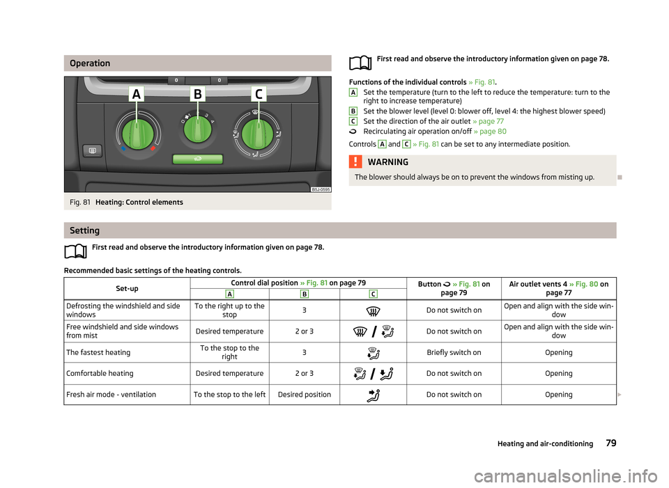
OperationFig. 81
Heating: Control elements
First read and observe the introductory information given on page 78.
Functions of the individual controls » Fig. 81 .
Set the temperature (turn to the left to reduce the temperature: turn to the right to increase temperature)
Set the blower level (level 0: blower off, level 4: the highest blower speed) Set the direction of the air outlet » page 77
Recirculating air operation on/off » page 80
Controls
A
and
C
» Fig. 81 can be set to any intermediate position.
WARNINGThe blower should always be on to prevent the windows from misting up.
ABC
Setting
First read and observe the introductory information given on page 78.
Recommended basic settings of the heating controls.
Set-upControl dial position » Fig. 81 on page 79Button » Fig. 81 on
page 79Air outlet vents 4 » Fig. 80 on
page 77ABCDefrosting the windshield and side
windowsTo the right up to the stop3Do not switch onOpen and align with the side win- dowFree windshield and side windows
from mistDesired temperature2 or 3
Do not switch onOpen and align with the side win-
dowThe fastest heatingTo the stop to theright3Briefly switch onOpeningComfortable heatingDesired temperature2 or 3
Do not switch onOpeningFresh air mode - ventilationTo the stop to the leftDesired positionDo not switch onOpening 79Heating and air-conditioning