2013 SKODA ROOMSTER brake light
[x] Cancel search: brake lightPage 114 of 219

Hill Hold Control (HHC)
When driving on slopes, HHC allows you to move your foot from the brake pedal
to the accelerator pedal without having to use the handbrake.
The system holds the brake pressure produced by the activation of the brakepedal for approx. 2 seconds after the brake pedal is released.
The brake pressure drops gradually the more you operate the accelerator pedal. Ifthe vehicle does not start off within 2 seconds, it starts to roll back.
HHC is active on slopes of >5 % when the driver door is closed. HHC is always only
active on slopes when in forward or reverse start off. When driving downhill, it is inactive.
Antilock Braking System (ABS)
First read and observe the introductory information and safety warn-
ings
on page 110.
ABS prevents the wheels locking when braking. Thus helping the driver to main-
tain control of the vehicle.
The intervention of the ABS is noticeable from the pulsating movements of the
brake pedal which is accompanied by noises.
When the ABS system is active, do not brake periodically or reduce the pressure
on the brake pedal.
Traction Control System (ASR)
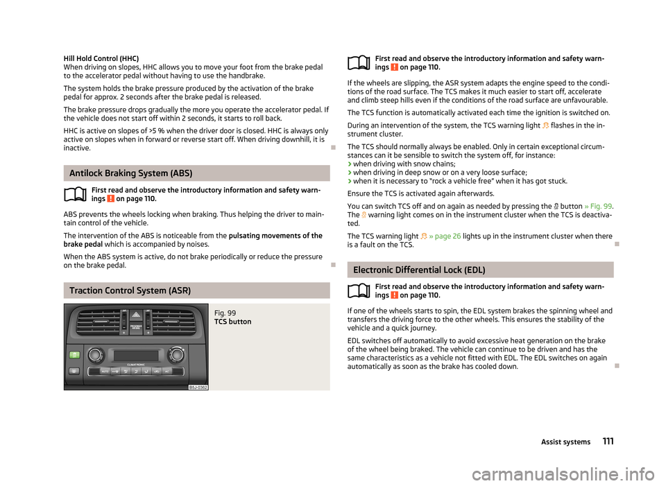
Fig. 99
TCS buttonFirst read and observe the introductory information and safety warn-
ings on page 110.
If the wheels are slipping, the ASR system adapts the engine speed to the condi-
tions of the road surface. The TCS makes it much easier to start off, accelerate
and climb steep hills even if the conditions of the road surface are unfavourable.
The TCS function is automatically activated each time the ignition is switched on.
During an intervention of the system, the TCS warning light flashes in the in-
strument cluster.
The TCS should normally always be enabled. Only in certain exceptional circum-
stances can it be sensible to switch the system off, for instance:
› when driving with snow chains;
› when driving in deep snow or on a very loose surface;
› when it is necessary to “rock a vehicle free” when it has got stuck.
Ensure the TCS is activated again afterwards.
You can switch TCS off and on again as needed by pressing the
button » Fig. 99 .
The
warning light comes on in the instrument cluster when the TCS is deactiva-
ted.
The TCS warning light
» page 26 lights up in the instrument cluster when there
is a fault on the TCS.
Electronic Differential Lock (EDL)
First read and observe the introductory information and safety warn-
ings
on page 110.
If one of the wheels starts to spin, the EDL system brakes the spinning wheel and
transfers the driving force to the other wheels. This ensures the stability of the
vehicle and a quick journey.
EDL switches off automatically to avoid excessive heat generation on the brake of the wheel being braked. The vehicle can continue to be driven and has the
same characteristics as a vehicle not fitted with EDL. The EDL switches on again
automatically as soon as the brake has cooled down.
111Assist systems
Page 116 of 219

Activation/deactivationFirst read and observe the introductory information and safety warn-
ings
on page 112.
The system is activated automatically by engaging reverse gear. This is confirmed
by a brief audible signal.
The system is deactivated by disengaging reverse gear.
Note
The system cannot be activated on vehicles with a factory-fitted towing device
when towing a trailer.
Cruise Control System
Introduction
This chapter contains information on the following subjects:
Storing a speed
114
Changing a stored speed
114
Switching off temporarily
114
Switching off completely
114
The Cruise Control System (CCS) maintains a set speed, more than 25 km/h, with-
out you having to actuate the accelerator pedal.
This is only possible within the range which is permitted by the power output and
braking power of the engine.
The
warning light in the instrument cluster lights up when the cruise control
system is switched on.
WARNING■ For safety reasons, the cruise control system must not be used in dense
traffic or on unfavourable road surfaces (such as icy roads, slippery roads,
loose gravel) – there is a risk of an accident.■
The saved speed may only be resumed if it is not too high for the current
traffic conditions.
■
Always deactivate the cruise control system after use to prevent the system
being switched on unintentionally.
CAUTION
■ The cruise control system is not able to maintain a constant speed when driving
in areas with steeper gradients. The weight of the vehicle increases the speed at which it travels. Therefore, shift to a lower gear in good time or slow the vehicle
down by applying the foot brake.■
It is not possible to switch on the cruise control system on vehicles fitted with a
manual gearbox if the first gear or reverse gear is engaged.
■
It is not possible on vehicles fitted with an automatic gearbox to switch on the
cruise control system if the selector lever is in the position P, N or R.
■
The Cruise Control System may automatically switch off when some brake as-
sist systems (e.g. ESC) intervene, when the speed exceeds maximum permissible
engine speed, or a similar event takes place.
113Assist systems
Page 118 of 219

START-STOP
Introduction
This chapter contains information on the following subjects:
Starting/shutting down the engine
115
Operating conditions for the system
115
Manually activating/deactivating the system
116
Information messages
116
The START-STOP system helps you to save fuel while at the same time reducing
harmful exhaust emissions and CO 2 emissions.
The function is automatically activated each time the ignition is switched on.
In the start-stop mode, the engine automatically switches to the vehicle's idle phase, e.g. when stopped at traffic lights. The engine restarts automatically
where necessary.
The system can work only if the following basic conditions are met. The driver's door is closed.
The driver has fastened the seat belt. The bonnet is closed.The driving speed exceeded 4 km/h after the last stop.
No trailer is coupled.
WARNING■ The brake servo unit and power steering only operate if the engine is run-
ning.■
Never let the vehicle roll with the engine switched off.
CAUTION
Always deactivate the START-STOP system before driving through wa-
ter » page 108 .Note■
If the driver's seat belt is removed for more than 30 seconds or the driver's door
is opened during stop mode, the engine will have to be started manually.■
After manually starting the engine, automatic engine shut down is not possible
until the vehicle has travelled the required minimum distance for START-STOP mode.
■
Changes to the outdoor temperature can have an effect on the internal temper-
ature of the vehicle battery even after several hours. If the vehicle remains out-
doors for a long time in minus temperatures or in direct sunlight, it can take sev-
eral hours until the internal temperature of the vehicle battery reaches a suitable
temperature for proper operation of the START STOP system.
■
If Climatronic is running in automatic mode, the engine may not switch off auto-
matically under certain conditions.
Starting/shutting down the engine
First read and observe the introductory information and safety warn-ings
on page 115.
›
Stop the vehicle (where necessary, apply the handbrake).
›
Shift the gear lever to Neutral.
›
Release the clutch pedal.
Automatic engine shut down (STOP phase) runs. The
warning symbol appears
in the instrument cluster display.
›
Depress the clutch pedal.
The new start procedure runs (START phase). The
warning symbol goes out.
Operating conditions for the system
First read and observe the introductory information and safety warn-
ings
on page 115.
The START-STOP system is very complex. Some of the procedures are hard to check without servicing.
No engine shut down runs
Before each STOP phase, the system checks whether certain conditions have
been met. No engine shut down runs in the following situations.
115Assist systems
Page 119 of 219

›The engine has not yet reached the minimum temperature for the START STOP
mode.
› The temperature inside the vehicle has not reached the desired temperature
set in the air-conditioning system/heating.
› The external temperature is very low/high.
› Intensive windscreen deicing (Climatronic) or windscreen deicing/ventilation is
switched on at the maximum air temperature setting (manual air conditioning
system).
› The parking aid is activated.
› The charge state of the vehicle battery is too low.
› The stationary vehicle is on a steep hill or a steep slope.
› The idling speed is too high.
› The steering angle is too great (manoeuvring).
The
warning symbol is being shown in the instrument cluster display.
The automatic start procedure runs again During the STOP phase, the engine fires up without any active driver intervention,
e.g. in the following situations.
› The vehicle has begun to roll, e.g. on a slope.
› The difference between the temperature setting of the air-conditioning sys-
tem/heating and the temperature of the interior is too great.
› Intensive windscreen deicing (Climatronic) or windscreen deicing/ventilation is
switched on at the maximum air temperature setting (manual air conditioning
system).
› The brake pedal was pressed several times (the pressure in the braking system
is too low).
› The charge state of the vehicle battery is too low.
› The current consumption is too high.
Manually activating/deactivating the system
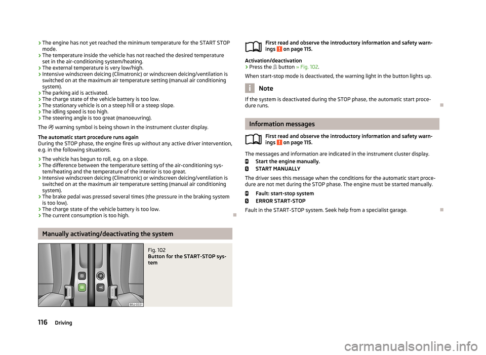
Fig. 102
Button for the START-STOP sys-
tem
First read and observe the introductory information and safety warn-
ings on page 115.
Activation/deactivation
›
Press the button » Fig. 102 .
When start-stop mode is deactivated, the warning light in the button lights up.
Note
If the system is deactivated during the STOP phase, the automatic start proce-
dure runs.
Information messages
First read and observe the introductory information and safety warn-
ings
on page 115.
The messages and information are indicated in the instrument cluster display.
Start the engine manually.START MANUALLY
The driver sees this message when the conditions for the automatic start proce- dure are not met during the STOP phase. The engine must be started manually.
Fault: start-stop system
ERROR START-STOP
Fault in the START-STOP system. Seek help from a specialist garage.
116Driving
Page 124 of 219

The distribution of the weight is very poor if your vehicle is unladen and the trail-
er is laden. Maintain a particularly low speed if you cannot avoid driving with this
combination.
Tyre pressure
Correct the tyre inflation pressure on your vehicle for a “full load” » page 173,
Service life of tyres .
Trailer load
The permissible trailer load must not be exceeded under any circumstan- ces » page 199 , Technical data .
The trailer loads specified apply only to altitudes up to 1 000 metres above mean
sea level.
The engine output falls as altitude increases, as does the ability to climb. There-
fore, for every additional 1000 m in height (or part), the maximum permissible
towed weight must be reduced by 10 %.
The towed weight comprises the actual weights of the (loaded) towing vehicleand the (loaded) trailer.
The trailer and drawbar load information on the type plate of the towing equip-
ment are merely test data for the towing equipment. The vehicle-specific values
are detailed in the vehicle documents.WARNING■ Do not exceed the maximum permissible axle and drawbar load and the
maximum permissible total or towed weight of the vehicle and the trailer –
there is the risk of an accident and serious injury.■
Slipping loads can significantly affect the stability and safety of the vehicle/
trailer combination – there is the risk of an accident and serious injury.
Towing a trailer
First read and observe the introductory information and safety warn-
ings
on page 120.
Exterior mirrors
You have to have additional exterior mirrors fitted if you are not able to see the
traffic behind the trailer with the standard rear-view mirrors. The national legal requirements must be observed.
Headlights
The front of the vehicle can be lifted when a trailer is being towed and the head- lights can dazzle other road users.
Adjust the headlight setting on the headlight range control » page 42, Headlight
beam adjustment .
Driving speed
For safety reasons, do not drive faster than 80 km/h when towing a trailer.
Immediately reduce your speed as soon as even the slightest swaying of the trail- er is detected. Never attempt to stop the trailer from “swaying” by accelerating.
Brakes
Apply the brakes in good time! If the trailer is fitted with a trailer brake, apply the
brakes gently at first, then brake firmly. This will avoid brake jolts resulting from
the trailer wheels locking.
On downhill sections shift down a gear in good time to also use the engine as a
brake.
Engine overheating
The speed must be reduced immediately if the needle for the coolant tempera-
ture gauge moves into the right-hand area or the red area of the scale.
Stop and switch off the engine if the warning light
in the instrument cluster
starts to flash. Wait a few minutes and check the level of coolant » page 166,
Checking the coolant level .
The following guidelines must be observed » page 22,
Coolant .
The coolant temperature can be reduced by switching on the heating.WARNING■ Adapt your speed to the conditions of the road surface and to the traffic sit-
uation.■
Improper or incorrectly connected electric cables can energise the trailer and
cause functional faults to the vehicle's entire electrical system as well as acci-
dents and severe injuries.
■
Work on the electrical system must only be carried out by specialist garages.
■
Never directly connect the trailer's electrical system with the electrical con-
nections for the tail lights or other current sources.
121Towing a trailer
Page 125 of 219

Note■After coupling the trailer and connecting up the power socket, check the rear
lights on the trailer to ensure they work.■
If there is an error in the trailer lighting system, check the fuses in the fuse box
in the dashboard » page 192.
■
If you tow a trailer frequently, you should also have your car inspected between
service intervals.
■
The handbrake on the towing vehicle must be applied when coupling and un-
coupling the trailer.
Anti-theft alarm system
First read and observe the introductory information and safety warn-
ings
on page 120.
When the vehicle is locked, the alarm is activated as soon as the electrical con- nection to the trailer is interrupted.
Always switch off the anti-theft alarm system before a trailer is coupled or uncou- pled » page 35 .
Conditions for including a trailer in the anti-theft alarm system. The vehicle is factory-fitted with an anti-theft alarm system and towingequipment.
The trailer is electrically connected to the towing vehicle by means of the
trailer socket.
The electrical system of the vehicle and trailer is functional. The vehicle is locked with the vehicle key and the anti-theft alarm system isactivated.
Note
For technical reasons, trailers with rear LED lights cannot be connected to the an-
ti-theft alarm system.
122Driving
Page 156 of 219

■When removing snow or ice from windows and mirror lenses ensure that the
paintwork of the vehicle is not to damage.■
Do not clean the inside of the windows with sharp-edged objects or corrosive
and acidic cleaning agents – there is a risk of damaging the heating elements or
window aerial.
Headlight lenses
First read and observe the introductory information and safety warn-ings
on page 150.
Clean plastic front headlight lenses using clean, warm water and soap.
CAUTION
■ Never wipe headlights to dry.■Do not use any sharp objects to clean the plastic lenses, as this may damage
the protective paintwork and consequently cause cracks to form on the headlight lenses.■
Do not use any harsh cleaning products or chemical solvents to clean the head-
lights, as this could damage the headlight lenses.
Door lock cylinders
First read and observe the introductory information and safety warn-
ings
on page 150.
Specific products must be used for de-icing door lock cylinders.
CAUTION
When washing your vehicle, ensure as little water as possible gets into the lock-
ing cylinders.
Cavity protection
First read and observe the introductory information and safety warn-
ings
on page 150.
All the cavities of your vehicle which are at risk from corrosion are protected for life by a layer of protective wax applied in the factory.
This wax protection does not need to be inspected or re-applied.
If any small amount of wax flow out of the cavities at high temperatures, these
must be removed with a plastic scraper and the stains cleaned using a petroleum cleaner.WARNINGSafety regulations should be observed when using petroleum cleaner to re-
move wax – risk of fire!
Wheels
First read and observe the introductory information and safety warn-
ings
on page 150.
Wheel rims
Also thoroughly wash the wheel rims when washing the vehicle on a regular ba- sis.
Regularly remove salt and brake abrasion, otherwise the rim material will be cor-
roded.
Damage to the paint layer on the wheel rims must be touched up immediately.
Light alloy wheels
After washing thoroughly and treat the wheel rims with a protective product for
light alloy wheels. Products which cause abrasion must not be used to treat the
wheel rims.
CAUTION
Severe layers of dirt on the wheels can also result in wheel imbalance. This may
show itself in the form of a wheel vibration which is transmitted to the steering
wheel which, in certain circumstances, can cause premature wear of the steering.
This means it is necessary to remove the dirt.
153Car care
Page 165 of 219

Engine compartment overviewFig. 128
Principle sketch: Engine compartment
First read and observe the introductory information and safety warn- ings
on page 159.
Coolant expansion reservoir
166
Windscreen washer fluid reservoir
162
Engine oil filler opening
165
Engine oil dipstick
164
Brake fluid reservoir
167
Vehicle battery
168
Note
The location of the inspection points in the engine compartment of petrol and
diesel engines is practically identical.
123456Radiator fan
First read and observe the introductory information and safety warn-
ings
on page 159.
The radiator fan is powered by an electric motor. Operation is controlled accord-
ing to the temperature of the coolant.
WARNINGAfter switching off the ignition, the fan may intermittently continue to oper-
ate for approx. 10 minutes.
Windscreen washer system
Fig. 129
Engine compartment: Wind-
screen washer fluid reservoir
First read and observe the introductory information and safety warn- ings on page 159.
The windscreen washer fluid reservoir is located in the engine compartment and
contains the cleaning fluid for the windscreen and rear window and for the head- light cleaning system.
The capacity of the container is about 3.5 litres and about 5.4 litres on vehicles
that have a headlight washing system 1)
.
Clear water is not sufficient to intensively clean the windscreen and headlights. We recommend using clean water together with a screen cleaner from the range
of ŠKODA Original Accessories (with antifreeze in winter), which will remove any
stubborn dirt.
1)
In some countries, 5.4 litres applies for both variants.
162General Maintenance