2013 SKODA ROOMSTER back light
[x] Cancel search: back lightPage 138 of 219
Side airbagsFig. 117
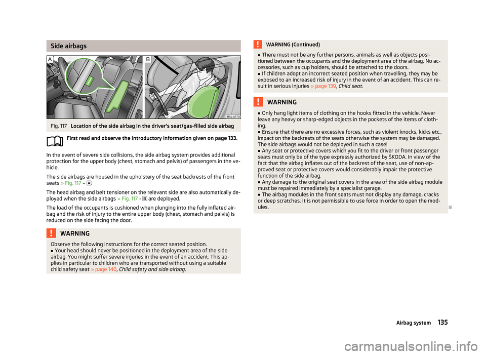
Location of the side airbag in the driver's seat/gas-filled side airbag
First read and observe the introductory information given on page 133.
In the event of severe side collisions, the side airbag system provides additional
protection for the upper body (chest, stomach and pelvis) of passengers in the ve-
hicle.
The side airbags are housed in the upholstery of the seat backrests of the front
seats » Fig. 117 –
.
The head airbag and belt tensioner on the relevant side are also automatically de-
ployed when the side airbags » Fig. 117 -
are deployed.
The load of the occupants is cushioned when plunging into the fully inflated air-
bag and the risk of injury to the entire upper body (chest, stomach and pelvis) is
reduced on the side facing the door.
WARNINGObserve the following instructions for the correct seated position.■Your head should never be positioned in the deployment area of the side
airbag. You might suffer severe injuries in the event of an accident. This ap-
plies in particular to children who are transported without using a suitable
child safety seat » page 140, Child safety and side airbag .WARNING (Continued)■
There must not be any further persons, animals as well as objects posi-
tioned between the occupants and the deployment area of the airbag. No ac-
cessories, such as cup holders, should be attached to the doors.■
If children adopt an incorrect seated position when travelling, they may be
exposed to an increased risk of injury in the event of an accident. This can re-
sult in serious injuries » page 139, Child seat .
WARNING■
Only hang light items of clothing on the hooks fitted in the vehicle. Never
leave any heavy or sharp-edged objects in the pockets of the items of cloth-
ing.■
Ensure that there are no excessive forces, such as violent knocks, kicks etc.,
impact on the backrests of the seats otherwise the system may be damaged.
The side airbags would not be deployed in such a case!
■
Any seat or protective covers which you fit to the driver or front passenger
seats must only be of the type expressly authorized by ŠKODA. In view of the
fact that the airbag inflates out of the backrest of the seat, use of non-ap-
proved seat or protective covers would considerably impair the protective
function of the side airbag.
■
Any damage to the original seat covers in the area of the side airbag module
must be repaired immediately by a specialist garage.
■
The airbag modules in the front seats must not display any damage, cracks
or deep scratches. It is not permissible to use force in order to open the mod-
ules.
135Airbag system
Page 167 of 219

Diesel enginesa)SpecificationCapacity1.2 litres/55 kW TDI CRVW 507 004.31.6 litres/66 kW TDI CR DPFVW 507 004.31.6 litres/77 kW TDI CR DPFVW 507 004.3a)
Engine oil VW 505 01 can optionally be used in diesel engines
without DPF
Specifications and capacity (in l) for vehicles with fixed service intervals
Petrol enginesSpecificationCapacity1.2 litres/51 kWVW 501 01, VW 502 002.81.2 litres/63 kW TSIVW 502 003.91.2 litres/77 kW TSIVW 502 003.91.4 litres/63 kWVW 501 01, VW 502 003.21.6 litres/77 kWVW 501 01, VW 502 003.6
If the oils specified above are not available, oils according to ACEA A2 or ACEA A3
can be used once for refilling.
Diesel engines a)SpecificationCapacity1.2 litres/55 kW TDI CRVW 507 004.31.6 litres/66 kW TDI CR DPFVW 507 004.31.6 litres/77 kW TDI CR DPFVW 507 004.3a)
Engine oil VW 505 01 can optionally be used in diesel engines
without DPF
If the oils specified above are not available, oils according to ACEA B3 or ACEA B4
can be used once for refilling.
CAUTION
Only the above-mentioned oils can be used on vehicles with flexible service inter- vals. We recommend always refilling with oil of the same specification since thiswill maintain the properties of the oil. In exceptional cases, a maximum of 0.5 l ofspecification VW 502 00 (only for petrol engines) or specification VW 505 01 (only
for diesel engines) engine oil can be used to refill once. Other engine oils must not be used - there is risk of engine damage.
Checking the oil levelFig. 130
Dipstick
First read and observe the introductory information and safety warn-
ings on page 163.
The dipstick indicates the engine oil level » Fig. 130.
Checking the oil level
Ensure that the vehicle is positioned on a level surface and the engine has reached its operating temperature.
›
Switch off the engine.
Wait a few minutes until the engine oil flows back into the sump.
›
Open the bonnet.
›
Pull out the dipstick.
›
Wipe the dipstick with a clean cloth and insert it again to the stop.
›
Pull the dipstick out again and check the oil level.
Oil level within range
A
No oil must be refilled.
Oil level within range
B
Oil can be refilled. The oil level may lie in range
A
.
Oil level within range
C
The engine must be topped up with oil so that the oil level at least reaches range
B
.
The engine burns some oil. The oil consumption may be as much as 0.5 l/1 000 km depending on your style of driving and the conditions under which you operate
your vehicle. Consumption may be slightly higher than this during the first 5 000
kilometres.
164General Maintenance
Page 179 of 219

WARNING■When the warning light illuminates, immediately reduce the speed and
avoid sudden steering and brake manoeuvres. Stop the vehicle as soon as
possible and inspect the tyres and their inflation pressure.■
Under certain circumstances (e.g. a racy style of driving, wintry or unpaved
roads), the warning light may be delayed or does not light up at all.
CAUTION
■
The tyre control display does therefore not replace the regular tyre inflation
pressure control, as the system cannot detect an even loss of pressure.■
The system cannot warn in case of very rapid loss of tyre pressure, e.g. in the
event of a sudden puncture. In this case carefully bring the vehicle to a standstill without sudden steering movements or sharp braking.
■
The basic setting must be repeated every 10,000 km or once a year to ensure
proper functioning of the tyre pressure monitor.
Spare wheel
Fig. 138
Boot: Spare wheel
First read and observe the introductory information and safety warn-
ings on page 172.
The spare wheel is located in a well under the floor covering in the luggage com-
partment and held by a special nut » Fig. 138.
Taking the wheel out
›
Open the tailgate.
›
Lift up the floor in the luggage compartment.
›
Remove the box with the tool kit.
›
Unscrew the nut » Fig. 138 anticlockwise.
›Take out the wheel.
Stowing the wheel›
Stow the replaced wheel in the spare wheel well with the rim facing down.
›
Screw on the nut » Fig. 138 clockwise until the wheel is safely secured.
›
Replace the box with the tool kit into the spare wheel and secure it with the
tape.
›
Fold back the floor in the luggage compartment.
›
Close the boot lid.
Fit a wheel in the appropriate dimensions and design as soon as possible.
If the dimensions or design of the spare wheel differ from the tyres fitted to the
vehicle (e.g. winter tyres or low-profile tyres), it must only be used briefly in the
event of a puncture and if an appropriately cautious style of driving is adop-
ted »
.
Temporary spare wheel
A warning label is displayed on the rim of the temporary spare wheel.
Please note the following if you intend to use the temporary spare wheel. › The warning label must not be covered after installing the wheel.
› Be particularly observant when driving.
› The inflation pressure for the temporary spare wheel is identical to the maxi-
mum inflation pressure for the standard tyres.
› Only use this temporary spare wheel to reach the nearest specialist garage, as it
is not intended for long-term use.
WARNING■ Never use the temporary spare wheel if it is damaged.■If the dimensions or design of the temporary spare wheel differ from the fit-
ted tyres, never drive faster than 80 km/h (or 50 mph).■
Avoid accelerating at full throttle, sharp braking and fast cornering.
CAUTION
Observe the instructions on the warning sticker on the temporary spare wheel.
176General Maintenance
Page 183 of 219
Note■The fire extinguisher must comply with national legal requirements.■Pay attention to the expiration date of the fire extinguisher. Proper functioning
of the fire extinguisher is not assured once it has passed its expiry date.■
The fire extinguisher is part of the scope of delivery in certain countries only.
Vehicle tool kit
Fig. 143
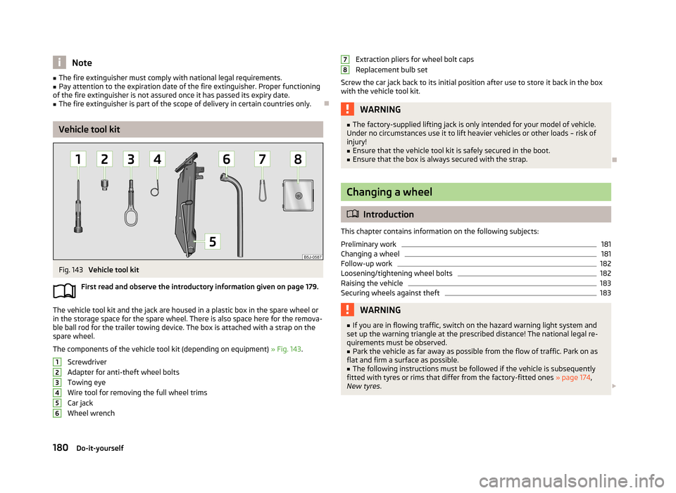
Vehicle tool kit
First read and observe the introductory information given on page 179.
The vehicle tool kit and the jack are housed in a plastic box in the spare wheel or
in the storage space for the spare wheel. There is also space here for the remova-
ble ball rod for the trailer towing device. The box is attached with a strap on the spare wheel.
The components of the vehicle tool kit (depending on equipment) » Fig. 143.
Screwdriver
Adapter for anti-theft wheel bolts Towing eye
Wire tool for removing the full wheel trims Car jack
Wheel wrench
123456Extraction pliers for wheel bolt caps
Replacement bulb set
Screw the car jack back to its initial position after use to store it back in the box with the vehicle tool kit.WARNING■ The factory-supplied lifting jack is only intended for your model of vehicle.
Under no circumstances use it to lift heavier vehicles or other loads – risk of
injury!■
Ensure that the vehicle tool kit is safely secured in the boot.
■
Ensure that the box is always secured with the strap.
Changing a wheel
Introduction
This chapter contains information on the following subjects:
Preliminary work
181
Changing a wheel
181
Follow-up work
182
Loosening/tightening wheel bolts
182
Raising the vehicle
183
Securing wheels against theft
183WARNING■ If you are in flowing traffic, switch on the hazard warning light system and
set up the warning triangle at the prescribed distance! The national legal re-
quirements must be observed.■
Park the vehicle as far away as possible from the flow of traffic. Park on as
flat and firm a surface as possible.
■
The following instructions must be followed if the vehicle is subsequently
fitted with tyres or rims that differ from the factory-fitted ones » page 174,
New tyres .
78180Do-it-yourself
Page 199 of 219
›Turn the socket with the bulb to the stop in the direction of the arrow
» Fig. 159
and remove it.›
Replace the bulb, insert the connector and new bulb and turn to the stop in the
opposite direction to that of the arrow.
›
Fit the rubber cover
1
.
Changing the high beam bulb (halogen projector headlights)
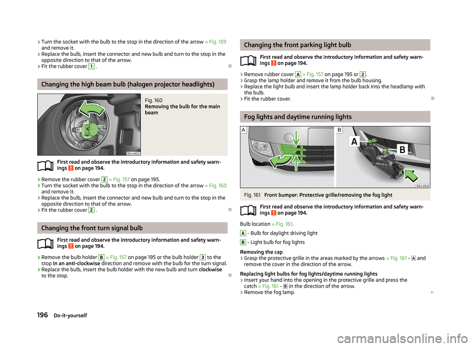
Fig. 160
Removing the bulb for the main
beam
First read and observe the introductory information and safety warn-
ings on page 194.
›
Remove the rubber cover
2
» Fig. 157 on page 195.
›
Turn the socket with the bulb to the stop in the direction of the arrow » Fig. 160
and remove it.
›
Replace the bulb, insert the connector and new bulb and turn to the stop in the
opposite direction to that of the arrow.
›
Fit the rubber cover
2
.
Changing the front turn signal bulb
First read and observe the introductory information and safety warn-ings
on page 194.
›
Remove the bulb holder
B
» Fig. 157 on page 195 or the bulb holder
3
to the
stop in an anti-clockwise direction and remove with the bulb for the turn signal.
›
Replace the bulb, insert the bulb holder with the new bulb and turn clockwise
to the stop.
Changing the front parking light bulb
First read and observe the introductory information and safety warn-
ings
on page 194.
›
Remove rubber cover
A
» Fig. 157 on page 195 or
2
.
›
Grasp the lamp holder and remove it from the bulb housing.
›
Replace the light bulb and insert the lamp holder back into the headlamp with
the bulb.
›
Fit the rubber cover.
Fog lights and daytime running lights
Fig. 161
Front bumper: Protective grille/removing the fog light
First read and observe the introductory information and safety warn-
ings
on page 194.
Bulb location » Fig. 161.
A
- Bulb for daylight driving light
B
- Light bulb for fog lights
Removing the cap
›
Grasp the protective grille in the areas marked by the arrows » Fig. 161 -
and
remove the cover in the direction of the arrow.
Replacing light bulbs for fog lights/daytime running lights
›
Insert your hand into the opening in the protective grille and press the catch » Fig. 161 -
in the direction of the arrow.
›
Remove the fog lamp.
196Do-it-yourself
Page 201 of 219
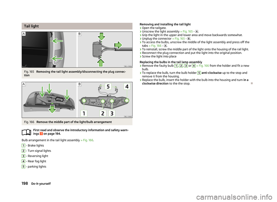
Tail lightFig. 165
Removing the tail light assembly/disconnecting the plug connec-
tion
Fig. 166
Remove the middle part of the light/bulb arrangement
First read and observe the introductory information and safety warn- ings
on page 194.
Bulb arrangement in the tail light assembly » Fig. 166.
1
- Brake lights
2
- Turn signal lights
3
- Reversing light
4
- Rear fog light
5
- parking lights
Removing and installing the tail light›Open the tailgate.›
Unscrew the light assembly » Fig. 165 - .
›
Grip the light in the upper and lower area and move backwards somewhat.
›
Unplug the connector » Fig. 165 - .
›
To access the bulbs, unscrew the middle of the light assembly and press off the
tabs » Fig. 166 - .
›
To reinstall, screw the middle part of the light onto the housing of the rail light.
›
Reconnect the plug connection and put the light into the original position.
›
Screw the light into place
Replacing the bulbs in the tail lamp assembly
›
Remove the faulty bulb
1
,
2
,
3
or
4
» Fig. 166 from the holder and fit a new
bulb.
›
To replace the bulb, turn the bulb holder
5
anti-clockwise up to the stop and
remove it from the housing.
›
Replace the bulb, insert the holder with the bulb into the housing and turn in a
clockwise direction to the the stop.
198Do-it-yourself
Page 213 of 219

Onboard computersee Multifunction display13
Operation in winter Diesel fuel
159
Vehicle battery170
Outside temperature15
Overview Engine compartment
162
warning lights20
P
Paintwork See Paintwork care
151
Paintwork care151
Panoramic roof48
Parking Parking aid
112
Parking lights41
Part replacement146
Passive safety Before setting off
123
Driving safety124
Safety equipment123
Passive Safety123
Pedals100
Footmats100
Petrol refer to Fuel
158
Polishing the paintwork See Taking care of your vehicle
151
Power steering95
Power window force limiter39
praktik adjusting the safety partition
75
Praktik73
Adjustable safety partition behind the front seats
74
emergency release of the loading area door75
Fastening the loading floor74
Internal lighting75
Internal lights75
R
Radiator fan
162
Radio reception See windows
152
Raise vehicle183
Rear-view mirror Exterior mirrors
51
Manually dimmed rear-view mirror51
Rear fog light44
rear seats in the longitudinal direction
54
Tilt the seat backrest54
Rear seats54
Rear Seats fold back into the starting position
56
Rear window heating47
Recirculated air mode Manual air conditioning
82
Recommended gear13
Refuelling157
Fuel157
Regulation Headlight beam
42
Remote control34
Synchronisation process35
Remote control key Replacing the battery
29
Repairs and technical alterations146
Replacing Bulb for the licence plate light
197
Bulbs194
Bulbs in the tail light198
Fuses191
Fuses in the dash panel192
Fuses in the engine compartment193
Vehicle battery171
Windscreen wiper blades50
Replenishing Coolant
167
Engine oil165
Windscreen washer fluid162
Running-in The first 1500 km
103
Running in Brake pads
104
Engine103
Tyres104
S
SAFE see Safe securing
32
SAFELOCK see Safe securing
32
Safe securing32
Safety123
Child safety139
Child safety seats139
Correct seated position124
Head restraints56
ISOFIX141
TOP TETHER143
Safety belts rear middle seat
130
Saving electrical energy104
Seals Taking care of your vehicle
152
Seat Adjusting
53
Seat belt warning light
21
Seat belt height adjuster130
Seat belts127
Belt tensioners131
Cleaning156
fastening and unfastening129
210Index
Page 214 of 219

Height adjustment130
Inertia reels130
The physical principle of a frontal collision128
Seats Head restraints
56
Heating53
Removing seats55
Seats and stowing52
Selector lever see Using the selector lever
101
Service147
Service display16
Service intervals144
Setting Heating
79
Manual air conditioning system82
Manually dimmed rear-view mirror51
Setting the clock Clock
12
Shifting gears Driving and saving energy
105
Side airbag135
Snow chains178
Spare wheel176
Speedometer11
Speed symbol Refer to Wheels
175
Spoiler148
Stalk Main beam
43
Turn signals43
START-STOP115
Manually activating/deactivating the system116
Operating conditions for the system115
Starting/shutting down the engine115
Starting and stopping the engine96
Starting engine Jump-starting
186
Starting the engine97
Jump-starting187
Starting the engine97
START STOP Information messages
116
Jump-starting188
Steering force assistance95
Steering wheel95
Storage68
Storage compartment Storage compartment on the driver's side
70
Storage compartment on the front passenger side
69
Storage Compartment Lighting
47
Storage compartments68
Flexible storage compartment73
Storage compartment in the front centre console 71
storage pockets on the front seat
70
Stowage compartment beneath the front seat
71
compartment for glasses70
compartments in the doors72
compartments in the luggage73
sun roof48
sunshade48
Sun visors48
Switching lights on and off41
Switching off the engine98
Synthetic leather155
T
Taking care of the vehicle Natural leather
155
Seat belts156
Taking care of your vehicle Automatic car wash system
150
Cavity protection153
Chrome parts152
Cleaning the wheels153
Decorative films152
Door lock cylinders153
Headlight lenses153
High-pressure cleaner150
Plastic parts151
Polishing the paintwork151
Rubber seals152
Taking care of the interior154
Taking care of your vehicle exterior150
Washing149
Washing by hand149
Wash system150
Wax treatment151
Taking care of your vehicles Fabric covers
156
Technical data199
Telephone86
Temporary spare wheel176
the rear seats fold down seat backrest and fold seat fully for- ward
55
Tiptronic102
Tools180
TOP TETHER143
Tourist lights44
Towing188
Towing a trailer117
Towing device Description
117
Drawbar load117
Use and care120
Towing eye Front
189
Rear189
Towing protection36
Traction Control System (ASR)111
Trailer117, 120
Loading120
Towing a trailer121
211Index