2013 SKODA ROOMSTER change wheel
[x] Cancel search: change wheelPage 135 of 219

Airbag system
Description of the airbag system
Introduction
This chapter contains information on the following subjects:
System description
132
Airbag deployment
132WARNING■ An airbag can only offer you optimal protection in combination with a fas-
tened seat belt .■
The airbag is not a substitute for the seat belt, but instead forms part of the
complete passive vehicle safety concept.
■
To ensure passengers are protected with the greatest possible effect when
the airbag is deployed, the front seats must be correctly adjusted to match
the body size » page 124, Correct seated position .
■
If you do not fasten the seat belts when driving, lean too far forward or
adopt an incorrect seated position, you are exposing yourself to increased risk of injury in the event of an accident.
WARNINGObserve the following instructions for handling the airbag system.■If there is a fault, the airbag system must be checked by a specialist garage
immediately. Otherwise, there is a risk of the airbag not being activated in the
event of an accident.■
No modifications of any kind must be made to parts of the airbag system.
■
Any work on the airbag system including the installation and removal of sys-
tem components due to other repair work (e.g. removal of the steering wheel) must only be carried out by a specialist garage.
■
Never make any changes to the front bumper or bodywork.
■
It is prohibited to manipulate individual parts of the airbag system as this
might result in the airbag being deployed.
■
The protective function of the airbag system is sufficient for only one acci-
dent. The airbag system must then be replaced if the airbag has been de-
ployed.
System description
First read and observe the introductory information and safety warn-ings
on page 132.
The functional status of the airbag system is indicated by the indicator light in
the instrument cluster » page 26.
When the airbags are deployed, they fill with gas and inflate.
A grey white or red, non-harmful gas is released when the airbag is inflated. This
is perfectly normal and is not an indication of a fire in the vehicle.
Depending on the vehicle equipment, the airbag system consists of the
following modules.
› Electronic control unit.
› Front airbag for the driver and the front passenger
» page 134.
› Side airbags
» page 135.
› Head airbags
» page 136.
› Airbag warning light in the instrument cluster
» page 26.
› Key switch for the front passenger airbag
» page 137.
› Warning light for the front passenger airbag deactivation/activation in the mid-
dle of the dash panel » page 137.
Note
■
The airbag system needs no maintenance during its working life.■If you sell your vehicle, provide the complete vehicle documentation to the new
owner. Please note that the information relating to the possibility of deactivating
the front passenger airbag must be included!■
When disposing of vehicle or parts of the airbag system, it is important to com-
ply with the national legal requirements.
Airbag deployment
First read and observe the introductory information and safety warn-
ings
on page 132.
The airbags inflate in fractions of a second and at a high speed in order to be able
to offer additional protection in the event of an accident.
The airbag system is only functional when the ignition is switched on.
132Safety
Page 152 of 219

WARNINGObserve the following instructions for handling the airbag system.■It is prohibited to manipulate individual parts of the airbag system, as this
might result in the airbag being deployed.■
Never install any airbag parts into the vehicle that have been removed from
old cars or have been recycled.
■
Never install damaged airbag parts in the vehicle. The airbags may then not
be deployed properly or even at all in the event of an accident.
■
No modifications of any kind must be made to parts of the airbag system.
WARNING■ A change to the vehicle's wheel suspension, including the use of non-ap-
proved wheels and tire combinations, can alter the functioning of the airbag system - risk of accident and fatal injury!■
Never make any changes to the front bumper or the bodywork.
Washing your car
Introduction
This chapter contains information on the following subjects:
Washing by hand
149
Automatic car wash systems
150
Washing with a high-pressure cleaner
150
The best way to protect your vehicle against harmful environmental influences is frequent washing.
How often the vehicle should be washed depends on factors such as: › Frequency of use.
› Parking situation (garage, under trees etc.).
› Season.
› Weather conditions.
› Environmental influences.
The longer insect residues, bird droppings, tree sap, road and industrial dust, tar,
soot particles, road salt and other aggressive deposits remain adhering to the
paintwork of your vehicle, the more detrimental their destructive effect can be.
High temperatures, such as those caused by intensive sun's rays, accentuate this
caustic effect.
It is essential to also thoroughly clean the underside of the vehicle at the end of
the winter.WARNING■ When washing your vehicle in the winter: Water and ice in the braking sys-
tem can affect the braking efficiency – risk of accident!■
Only wash the vehicle when the ignition is switched off – risk of accident!
CAUTION
Do not wash your vehicle in bright sunlight – risk of paint damage.
For the sake of the environment
Only wash the vehicle at washing bays intended for this purpose.
Washing by hand
First read and observe the introductory information and safety warn-
ings
on page 149.
Soak the dirt with plenty of water and rinse as well as possible.
Clean the vehicle with a soft sponge, a washing glove or a washing brush . Work
from the top to the bottom - starting with the roof.
Only use a car shampoo for stubborn dirt.
Wash out the sponge or washing glove thoroughly at short intervals.
Clean wheels, door sills and similar parts last. Use a second sponge for such
areas.
Give the vehicle a good rinse after washing it and dry it off using a chamois leath- er.
149Car care
Page 158 of 219

Natural leatherFirst read and observe the introductory information and safety warn-
ings
on page 154.
Leather is a natural material with specific properties, and requires regular clean-
ing and maintenance.
The leather should be cleaned on a regular basis depending on the amount of
wear-and-tear.
Dust and dirt in the pores and folds act as abrasive materials. This leads to severe corrosion and the premature brittleness of the leather surface.
We recommend that you remove dust regularly and at short intervals using a
cloth or vacuum cleaner.
Clean soiled leather surfaces with a water-dampened cotton or woollen cloth and
then dry with a clean, dry cloth »
.
Clean severely soiled areas with a cloth soaked in a mild soap solution (2 table-
spoons of neutral soap to 1 litre of water).
To remove stains, use a cleaning agent specially designed for this purpose.
Treat the leather regularly and at suitable intervals using a suitable leather care
product.
CAUTION
■ Ensure that no part of the leather is soaked through during cleaning and that
no water gets into the seams. Otherwise, the leather could become brittle or
cracked.■
Avoid leaving the vehicle for lengthy periods in bright sunlight to avoid the
leather from bleaching. If the vehicle is parked in the open for lengthy periods, protect the leather from direct sunlight by covering it.
■
Sharp-edged objects on items of clothing such as zip fasteners, rivets, sharp-
edged belts, jewellery and pendants may leave permanent scratches or signs of
rubbing on the surface. Such damage cannot be subsequently recognised as a
justified complaint.
■
The use of a mechanical steering wheel lock may damage the leather surface of
the steering wheel.
■ Use a care cream with light blocker and impregnation effect on a regular basis
and each time after cleaning. The cream nourishes the leather, allows it to
breathe and keeps it supple and also provides moisture. It also creates surface
protection.■
Some clothing materials, e.g. dark denim, do not have sufficient colour fastness.
This can cause damage or clearly visible discolouration to seat covers, even when used correctly. This applies particularly to light-coloured seat covers. This does
not relate to a fault in the seat cover, but rather to poor colour fastness of the
clothing textiles.
Note
When using the vehicle, minor visible changes may occur to the leather parts of
the covers (e.g. wrinkles or creases) as a result of the stress applied to the covers.
Synthetic leather, fabrics and Alcantara ®
First read and observe the introductory information and safety warn- ings
on page 154.
Artificial leather
Clean artificial leather with a damp cloth.
If this method does not completely clean the artificial leather, use a mild soap sol-ution or cleaning products specially designed for this purpose.
Fabric
Clean upholstery cover materials and cloth trims on doors, boot cover, etc. using
specific cleaning agents, e.g., dry foam.
Use a soft sponge, brush, or commercially available microfibre cloth.
Use a cloth and special detergent to clean the headlining.
Remove any lumps on the cover fabric and any fabric residue using a brush.
Remove stubborn hair using a “cleaning glove”.
Alcantara ®
Dust and fine dirt particles in pores, creases and seams may chafe and damage the surface.
If you leave your vehicle parked in the open for lengthy periods, protect the Al-
cantara ®
seat upholstery from direct sunlight to prevent fading.
Minor changes in colour caused by use are normal.
155Car care
Page 178 of 219

545 kg
615 kg
630 kg
650 kg
Speed symbol
This indicates the maximum permissible vehicle speed with fitted tyres in each
category.
170 km/h
180 km/h
190 km/h
200 km/h
210 km/h
240 km/h
270 km/h
CAUTION
The information about the load index and the speed symbol is listed in your vehi-
cle documents.
Unidirectional tyres
First read and observe the introductory information and safety warn-
ings
on page 172.
The direction of rotation of the tyres is marked by arrows on the wall of the tyre.
The indicated direction of rotation must be adhered to in order to ensure the op- timal characteristics of these tyres.
These characteristics mainly relate to the following: › Increased driving stability.
› Reduced risk of aquaplaning.
› Reduced tyre noise and tyre wear.
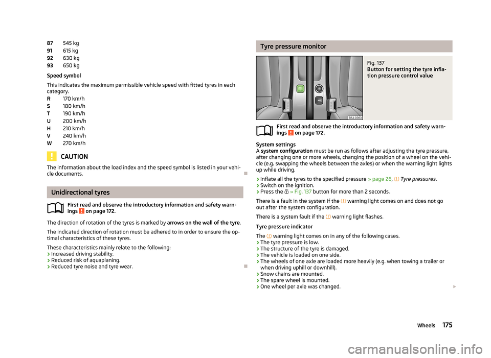
87919293RSTUHVWTyre pressure monitorFig. 137
Button for setting the tyre infla-
tion pressure control value
First read and observe the introductory information and safety warn-
ings on page 172.
System settings
A system configuration must be run as follows after adjusting the tyre pressure,
after changing one or more wheels, changing the position of a wheel on the vehi- cle (e.g. swapping the wheels between the axles) or when the warning light lights
up while driving.
›
Inflate all the tyres to the specified pressure » page 26,
Tyre pressures .
›
Switch on the ignition.
›
Press the
» Fig. 137 button for more than 2 seconds.
There is a fault in the system if the
warning light comes on and does not go
out after the system configuration.
There is a system fault if the
warning light flashes.
Tyre pressure indicator
The
warning light comes on in any of the following cases.
› The tyre pressure is low.
› The structure of the tyre is damaged.
› The vehicle is loaded on one side.
› The wheels of one axle are loaded more heavily (e.g. when towing a trailer or
when driving uphill or downhill).
› Snow chains are mounted.
› The spare wheel is mounted.
› One wheel per axle was changed.
175Wheels
Page 184 of 219

WARNINGObserve the following instructions for lifting the vehicle.■If the wheel has to be changed on a slope, first of all block the opposite
wheel with a stone or similar object to prevent the vehicle from unexpectedly
rolling away.■
Secure the base plate of the lifting jack with suitable means to prevent pos-
sible moving. A soft and slippery ground under the base plate may move the lifting jack, causing the vehicle to fall down. It is therefore always necessary to
place the lifting jack on a solid surface or use a wide and stable base. Use a non-slip base (e.g. a rubber foot mat) if the surface is smooth, such as cobbled
stones, tiled floor, etc.
■
Only attach the lifting jack to the attachment points provided for this pur-
pose.
■
Always raise the vehicle with the doors closed.
■
Never position any body parts, such as arms or legs under the vehicle, while
the vehicle is raised with a lifting jack.
■
Never start the engine when the vehicle is raised – risk of injury.
CAUTION
■ The tightening torque specified for the wheel bolts for steel and light alloy
wheels is 120 Nm.■
The anti-theft wheel bolt or the adapter can be damaged if the wheel bolts are
tightened too much.
Note
■ The anti-theft wheel bolt set and adapter can be purchased from a ŠKODA Part-
ner.■
The national legal requirements must be observed when changing a wheel.
Preliminary work
First read and observe the introductory information and safety warn-ings
on page 180.
Always change a wheel on a level surface as far as possible.
The following steps must be carried out before actually changing the wheel:
› Have
all the occupants get out. The passengers should not stand on the road
(instead they should remain behind a crash barrier, for instance) while the wheel is being changed.›
Switch off the engine.
›
Move the gearshift lever into Neutral or move the selector lever for the auto-
matic gearbox into position P.
›
Apply the handbrake firmly.
›
Uncouple a trailer.
›
Remove the vehicle tool kit » page 180 and the spare wheel » page 176 , Spare
wheel from the boot.
Changing a wheel
First read and observe the introductory information and safety warn-
ings
on page 180.
›
Remove the full wheel trim » page 177 or caps » page 177 .
›
In the case of light alloy wheel rims remove the wheel trim cap » page 177.
›
First of all slacken the anti-theft wheel bolt and then the other wheel
bolts » page 182 .
›
Jack up the vehicle until the wheel that needs changing is clear of the
ground » page 183 .
›
Unscrew the wheel bolts and place them on a clean surface (cloth, paper, etc.).
›
Remove the wheel carefully.
›
Attach the spare wheel and slightly screw on the wheel bolts.
›
Lower the vehicle.
›
Tighten the opposite wheel bolts alternately (cross-wise) with the wheel
wrench. Tighten the anti-theft wheel bolt last » page 182.
›
Reinstall the wheel trim/wheel trim cap or the caps.
Note
■
All bolts must be clean and must turn easily.■Under no circumstances grease or oil the wheel bolts!■
When fitting unidirectional tyres, ensure that the direction of rotation is cor-
rect » page 172 .
181Emergency equipment and self-help
Page 188 of 219

Breakdown kitFig. 148
Components of the breakdown kit
First read and observe the introductory information and safety warn-
ings
on page 184.
The kit is located in a box under the floor covering in the luggage compartment.
Components of the breakdown kit Valve remover
Sticker with “max. 80 km/h”/“max. 50 mph” speed designation
Inflation hose with plug
Air compressor
Tyre inflation hose
Tyre inflation pressure indicator
Air release valve
ON and OFF switch
12 volt cable connector
Tyre inflator bottle with sealing agent
Replacement valve core
The valve remover
1
has a slot at its lower end which fits into the valve core.
This is the only way in which you can remove and re-install the valve core from
the tyre valve. The same also applies to the replacement valve core
11
.
1234567891011Preparations for using the breakdown kit
First read and observe the introductory information and safety warn-
ings
on page 184.
The following preparatory work must be carried out before using the breakdown
kit.
›
Park the vehicle as far away as possible from the flow of traffic. Park on as flat and firm a surface as possible.
›
If you are in flowing traffic, switch on the hazard warning light system and setup the warning triangle at the prescribed distance! The national legal require-
ments must be observed.
›
Have all the occupants get out. The passengers should not stand on the road
(instead they should remain behind a crash barrier, for instance) while the wheel is being changed.
›
Switch off the engine and move the gearshift lever into Neutral or move the se-
lector lever on the automatic gearbox into position P.
›
Apply the handbrake firmly.
›
Check that you can carry out the repairs with the breakdown kit » page 184.
›
Uncouple a trailer.
›
Remove the breakdown kit from the boot.
›
Stick the sticker
2
» Fig. 148 on page 185 on the dashboard in the driver's field
of view.
›
Do not remove the foreign body, e.g. screw or nail, from the tyre.
›
Unscrew the valve cap.
›
Use the valve remover
1
to unscrew the valve core and place it on a clean sur-
face (rag, paper, etc.).
Sealing and inflating the tyre
First read and observe the introductory information and safety warn-
ings
on page 184.
Sealing
›
Shake the tyre inflator bottle
10
» Fig. 148 on page 185 vigorously several times.
›
Firmly screw the inflation hose
3
onto the tyre inflator bottle
10
in a clockwise
direction. The film on the cap is pierced automatically.
›
Remove the plug from the inflation hose
3
and plug the open end fully onto
the tyre valve.
›
Hold the bottle
10
with the bottom facing upwards and fill all of the sealing
agent from the tyre inflator bottle into the tyre.
185Emergency equipment and self-help
Page 197 of 219

No.Consumer5Interior6Glow plugs, radiator fan7Electrohydraulic power steering8ABS or TCS or ESC9Radiator fan10Automatic gearbox11ABS or TCS or ESC12Central control unit13Electrical auxiliary heating system
Note
Fuses 1-7 are replaced by a specialist garage.
Bulbs
Introduction
This chapter contains information on the following subjects:
Headlights
195
Changing the low beam and high beam bulb (halogen headlights)
195
Changing the high beam bulb (halogen projector headlights)
195
Changing the high beam bulb (halogen projector headlights)
196
Changing the front turn signal bulb
196
Changing the front parking light bulb
196
Fog lights and daytime running lights
196
Fog light, Roomster Scout
197
Replacing the bulb for the licence plate light
197
Tail light
198
Some manual skills are required to change a bulb. For this reason, we recommend
having bulbs replaced by a specialist garage or seeking other expert help in the
event of any uncertainties.
› Switch off the ignition and all of the lights before replacing a bulb.
› Faulty bulbs must only be replaced with the same type of bulbs. The designa-
tion is located on the light socket or the glass bulb.
› A stowage compartment for replacement bulbs is located in a plastic box in the
spare wheel or underneath the floor covering in the boot.WARNING■ Accidents can be caused if the road in front of the vehicle is not sufficiently
illuminated and the vehicle cannot or can only be seen with difficulty by other
road users.■
Always read and observe the warnings before completing any work in the
engine compartment » page 159, Engine compartment .
■
Bulbs H7 and H4 are pressurised and may burst when changed - there is a
risk of injury. We therefore recommended wearing gloves and safety glasses
when changing a bulb.
CAUTION
■ Do not take hold of the glass bulb with naked fingers (even the smallest
amount of dirt reduces the working life of the light bulb). Use a clean cloth, nap-
kin, or similar.■
When removing and installing the number plate light and tail light make sure
that the paintwork of the vehicle and the tail light are not damaged.
Note
■ This Owner's Manual only describes the replacement of bulbs where it is possi-
ble to replace the bulbs on your own without any complications arising. Other bulbs must be replaced by a specialist garage.■
We recommend that a box of replacement bulbs always be carried in the vehi-
cle. Replacement bulbs can be purchased from ŠKODAOriginal Accessories.
■
We recommend having the headlight settings checked by a specialist garage af-
ter replacing a bulb in the main or low beam.
■
Visit a specialist garage if an LED is faulty.
194Do-it-yourself