2013 SKODA OCTAVIA wheel
[x] Cancel search: wheelPage 240 of 287
WARNING■The factory-supplied lifting jack is only intended for your model of vehicle.
Under no circumstances attempt to lift heavier vehicles or other loads – risk of
injury!■
Ensure that the vehicle tool kit is safely secured in the luggage compart-
ment.
■
Ensure that the box is always secured with the strap.
Changing a wheel
Introduction
This chapter contains information on the following subjects:
Preparation
237
Changing a wheel
238
Follow-up tasks
238
Loosening/tightening wheel bolts
239
Raising the vehicle
239
Securing wheels against theft
240WARNING■ If you are in flowing traffic, switch on the hazard warning light system and
set up the warning triangle at the prescribed distance! The national legal re-
quirements must be observed.■
Park the vehicle as far away as possible from the flow of traffic. Park on as
flat and firm a surface as possible.
■
If the vehicle is subsequently fitted with tyres which are different from
those it was fitted with at the works, follow these guidelines » page 230, New
tyres .
WARNINGObserve the following instructions for lifting the vehicle.■If the wheel has to be changed on a slope, first of all block the opposite
wheel with a stone or similar object to prevent the vehicle from unexpectedly
rolling away.■
Secure the base plate of the lifting jack with suitable means to prevent pos-
sible moving. A soft and slippery ground under the base plate may move the lifting jack, causing the vehicle to fall down. It is therefore always necessary to
place the lifting jack on a solid surface or use a wide and stable base. Use a non-slip base (e.g. a rubber foot mat) if the surface is smooth, such as cobbled
stones, tiled floor, etc.
■
Only attach the lifting jack to the attachment points provided for this pur-
pose.
■
Always raise the vehicle with the doors closed.
■
Never position any body parts, such as arms or legs under the vehicle, while
the vehicle is raised with a lifting jack.
■
Never start the engine with the vehicle sitting on the raised jack – risk of in-
jury.
CAUTION
■ The tightening torque specified for the wheel bolts for steel and light alloy
wheels is 120 Nm.■
If the wheel bolts are fastened too tightly, this can cause damage to the anti-
theft wheel bolt or the adapter.
Note
The national legal requirements must be observed when changing a wheel.
Preparation
First read and observe the introductory information and safety warn-
ings
on page 237.
Always change a wheel on a level surface as far as possible.
The following steps must be carried out before actually changing the wheel:
237Emergency equipment, and self-help
Page 241 of 287

›Have
all of the occupants get out of the vehicle. While changing a tyre, the oc-
cupants of the vehicle should not stand on the road (they should instead remain
behind a crash barrier).›
Switch off the engine.
›
Move the gearshift lever into Neutral or move the selector lever for the auto-
matic gearbox into position P.
›
Firmly apply the handbrake.
›
Uncouple any trailers.
›
Remove the vehicle tool kit » page 236 and the spare wheel » page 232 from
the luggage compartment.
Changing a wheel
First read and observe the introductory information and safety warn-
ings
on page 237.
›
Remove the full wheel trim » page 233 or caps » page 233 .
›
First of all slacken the anti-theft wheel bolt and then the other wheel
bolts » page 239 .
›
Jack up the vehicle until the wheel that needs changing is clear of the
ground » page 239 .
›
Unscrew the wheel bolts and place them on a clean surface (cloth, paper, etc.).
›
Remove the wheel carefully.
›
Attach the spare wheel and slightly screw on the wheel bolts.
›
Lower the vehicle.
›
Tighten the wheel bolts opposite each other using the wheel wrench (alternat-
ing crosswise). Tighten the anti-theft wheel bolt last » page 239.
›
Replace the wheel trim or the caps.
Note
■
All bolts must be clean and must turn easily.■Under no circumstances grease or oil the wheel bolts!■
When fitting unidirectional tyres, ensure that the direction of rotation is cor-
rect » page 228 .
Follow-up tasks
First read and observe the introductory information and safety warn-
ings
on page 237.
The following steps must also be performed after changing the wheel.
›
Stow and attach the replaced wheel in the spare wheel well using a special bolt » page 232 .
›
Stow the tool kit in the space provided and secure using the band.
›
Check the tyre pressure on the installed spare wheel as soon as possible.
›
Have the tightening torque of the wheel bolts checked with a torque wrench
as soon as possible.
›
Replace the damaged wheel or consult a specialist garage about repair options.
Note
■ If it is determined that the wheel bolts are corroded and difficult to turn when
changing the wheel, the bolts must be replaced before checking the tightening
torque.■
Drive cautiously and only at a moderate speed until the tightening torque has
been checked.
238Do-it-yourself
Page 242 of 287

Loosening/tightening wheel boltsFig. 198
Changing a wheel: Loosening
the wheel bolts
First read and observe the introductory information and safety warn-
ings on page 237.
Release
›
Push the wheel wrench onto the wheel bolt to the stop 1)
.
›
Grasp the end of the wrench and turn the bolt about one turn in the direction of
the arrow » Fig. 198.
Tightening
›
Push the wheel wrench onto the wheel bolt to the stop 1 )
.
›
Grasp the end of the wrench and turn the bolt against the direction of the ar-
row » Fig. 198 , until it is tight.
WARNINGUndo the wheel bolts only a little (about one turn) as long as the vehicle has
not yet been jacked up. Otherwise the wheel could come off and fall down –
risk of injury!
Note
If it proves difficult to undo the bolts, carefully apply pressure to the end of the
wrench with your foot. Keep hold of the vehicle when doing so, and make sure
you keep your footing.
Raising the vehicleFig. 199
Jacking points for positioning
lifting jack
Fig. 200
Attach lifting jack
First read and observe the introductory information and safety warn-
ings
on page 237.
Position the lifting jack below the jacking point closest to the faulty wheel » Fig. 199 . The jacking point is located directly below the engraving in the
lower sill.
›
Insert the crank into the mount on the car jack » page 236.
›
Position the lifting jack below the jacking point with the crank and move it up
until its claw is positioned below the vertical web of the lower sill.
›
Align the lifting jack so that its claw grasps the web » Fig. 200 -
.
›
Support the base plate of the lifting jack with its entire surface resting on level
ground and ensure that the lever is positioned vertically to the point at which
the claw grasps the web » Fig. 200 -
.
1)
Use the appropriate adapter for undoing and tightening the anti-theft wheel bolts
» page 240.
239Emergency equipment, and self-help
Page 243 of 287

›Continue turning up the jack until the wheel is just about lifted off the ground.WARNING■
Only raise the vehicle at the attachment points.■Choose a flat and firm surface for jacking the vehicle.
Securing wheels against theft
Fig. 201
Principle sketch: Anti-theft
wheel bolt with adapter
First read and observe the introductory information and safety warn-
ings on page 237.
The anti-theft wheel bolts can only be removed/tightended with the aid of theadapter » page 236 , Vehicle tool kit .
›
Remove the cover from the anti-theft wheel bolt.
›
Insert the adapter
B
» Fig. 201 with its toothed side fully into the inner tooth-
ing of the anti-theft wheel bolt
A
until the stop so that only the outer hexagon
is jutting out.
›
Push the wheel wrench onto the adapter
B
up to the stop.
›
Loosen or tighten the wheel bolt » page 239
.
›
After removing the adapter, replace the cap on the anti-theft wheel bolt.
›
Have the tightening torque checked with a torque wrench as soon as possible.
Note■
Make a note of the code number hammered into the rear side of the adapter or
the rear side of the anti-theft wheel bolt. This number can be used to purchase a
replacement adapter from ŠKODA Genuine Parts if required.■
We recommend that you always carry the adapter for the wheel bolts with you
in the vehicle. It should be stowed in the vehicle tool kit.
■
The anti-theft wheel bolt set and adapter can be purchased from a ŠKODA Part-
ner.
Tyre repair
Introduction
This chapter contains information on the following subjects:
Breakdown kit
241
Preparations for using the breakdown kit
241
Sealing and inflating the tyre
242
Check after 10 minutes' driving
242
Use the breakdown kit to reliably repair tyre damage caused by foreign bodies or
a puncture with diameters up to approx. 4 mm.
Performing a repair with the breakdown kit not at all intended to replace a per-
manent repair on the tyre. Its purpose is to get you to the nearest specialist ga-
rage.
The wheel must not be removed during repair.
Do not remove foreign bodies , e.g. screws or nails, from the tyre.
The breakdown kit must not be used under the following circumstances. › There is damage to the rim.
› The outside temperature is less than -20 °C.
› The tears or punctures are greater than 4 mm in size.
› There is damage to the tyre wall.
› Driving with very low tyre pressure or with a completely flat tyre.
› If the use-by-date (see inflation bottle) has passed.
240Do-it-yourself
Page 247 of 287

Both batteries must have a rated voltage of 12 V. The capacity (Ah) of the battery
supplying the power must not be significantly less than the capacity of the dis-
charged battery in your vehicle.
Jump-start cables
Only use jump-start cables which have an adequately large cross-section and in-
sulated terminal clamps. Observe the instructions of the jumper lead manufactur-
er.
Positive cable – colour coding in the majority of cases is red.
Negative cable – colour coding in the majority of cases is black.
Jump-starting in vehicles with the START-STOP system
Fig. 204
Engine earth: START-STOP sys-
tem
First read and observe the introductory information and safety warn- ings on page 243.
On vehicles with the START-STOP system, the jump-start cable of the charger
must never be connected directly to the negative pole of the vehicle battery, but
only to the engine earth » Fig. 204.
Towing the vehicle
Introduction
This chapter contains information on the following subjects:
Front towing eye
245
Rear towing eye
245
Vehicles with a tow hitch
246Vehicles with manual transmission may be towed in with a tow bar or a tow rope
or with the front or rear wheels raised.
Vehicles with automatic transmission may be towed in with a tow bar or a tow
rope or with the front wheels raised. If the vehicle is raised at rear, the automatic
gearbox is damaged!
A tow bar is the safest way of towing a vehicle and also minimises any shocks.
Only use a tow rope if a suitable tow bar is not available.
When towing, the following guidelines must be observed.
Driver of the tow vehicle›
Release the clutch particularly gently when starting off or depress the accelera-
tor particularly gently if the vehicle is fitted with an automatic gearbox.
›
On vehicles with a manual transmission, only push down on the accelerator
pedal once the rope is taught.
The maximum towing speed is 50 km/h.
Driver of the towed vehicle
›
Switch on the ignition so that the steering wheel is not blocked and so that the
turn signal lights, horn, windscreen wipers and windscreen washer system can be used.
›
Take the vehicle out of gear or move the selector lever into position N if the ve-
hicle is fitted with an automatic gearbox.
Please note that the brake servo unit and power steering only operate if the en-
gine is running. If the engine is not running, significantly more physical force is re- quired to depress the brake pedal and steer the vehicle.
If using a tow rope, ensure that it is always kept taught.
CAUTION
■ Do not tow start the engine – there is a risk of damaging the engine and the
catalytic converter. The battery from another vehicle can be used as a jump-start
aid » page 243 , Jump-starting .■
If the gearbox no longer contains any oil because of a defect, your vehicle must
only be towed with the driven wheels raised clear of the ground or on a special
breakdown vehicle or trailer.
■
The vehicle must be transported on a special breakdown vehicle or trailer if it is
not possible to tow in the vehicle in the way described or if the towing distance is
greater than 50 km.
■
To protect both vehicles when tow-starting or towing, the tow rope should be
elastic. Thus one should only use plastic fibre rope or a rope made out of a simi-
larly elastic material.
244Do-it-yourself
Page 248 of 287
■While towing, take care to avoid impermissibly high tensile forces or jerky loads.
There is always a risk of excessive stresses and damage resulting at the points to which you attach the tow rope or tow bar when you attempt to tow a vehicle
which is not standing on a paved road.■
Attach the tow rope or the tow bar to the towing eyes » page 245 , Front tow-
ing eye or » page 245 , Rear towing eye to the detachable ball head of the tow-
ing device » page 169 .
Note
■
We recommend using a tow rope from ŠKODA Original Accessories available
from a ŠKODA Partner.■
Towing another vehicle requires a certain amount of practice. Both drivers
should be familiar with the particular points about towing a vehicle. Unskilled
drivers should not attempt to tow in another vehicle or to be towed in.
■
When towing, respect the national legal provisions, especially those which re-
late to the identification of the towing vehicle and the vehicle being towed.
■
The tow rope must not be twisted as it may in certain circumstances result in
the front towing eye being unscrewed out of your vehicle.
Front towing eye
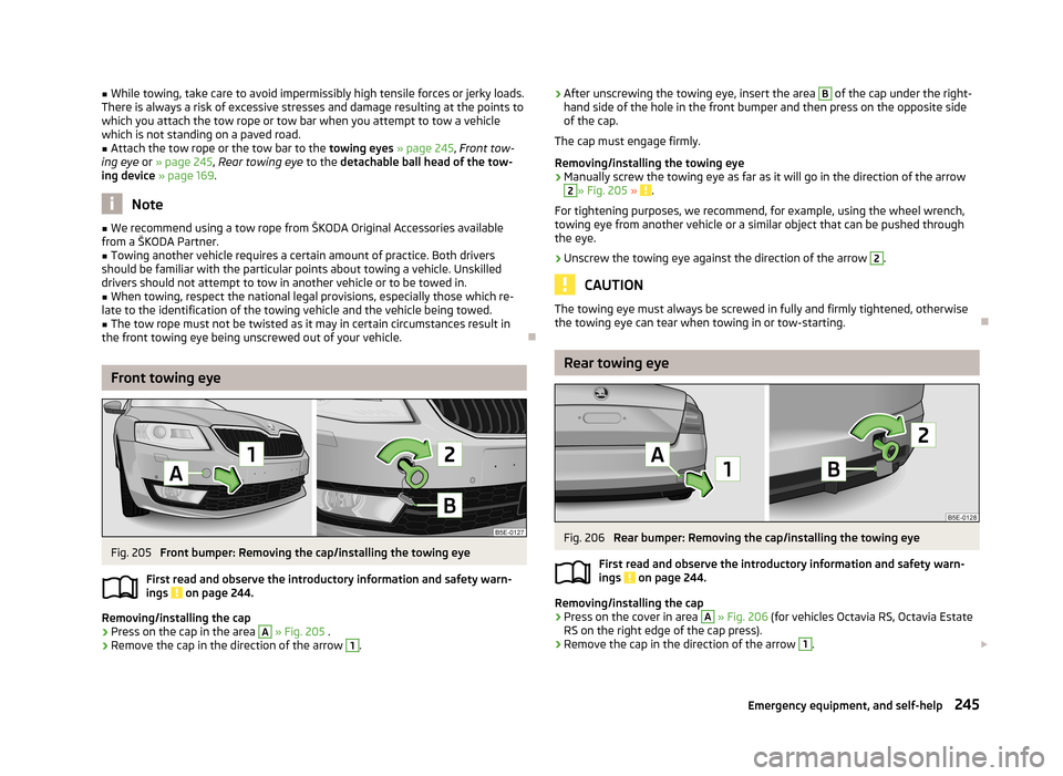
Fig. 205
Front bumper: Removing the cap/installing the towing eye
First read and observe the introductory information and safety warn- ings
on page 244.
Removing/installing the cap
›
Press on the cap in the area
A
» Fig. 205 .
›
Remove the cap in the direction of the arrow
1
.
›After unscrewing the towing eye, insert the area B of the cap under the right-
hand side of the hole in the front bumper and then press on the opposite side
of the cap.
The cap must engage firmly.
Removing/installing the towing eye›
Manually screw the towing eye as far as it will go in the direction of the arrow
2
» Fig. 205 » .
For tightening purposes, we recommend, for example, using the wheel wrench,
towing eye from another vehicle or a similar object that can be pushed through
the eye.
›
Unscrew the towing eye against the direction of the arrow
2
.
CAUTION
The towing eye must always be screwed in fully and firmly tightened, otherwise
the towing eye can tear when towing in or tow-starting.
Rear towing eye
Fig. 206
Rear bumper: Removing the cap/installing the towing eye
First read and observe the introductory information and safety warn- ings
on page 244.
Removing/installing the cap
›
Press on the cover in area
A
» Fig. 206 (for vehicles Octavia RS, Octavia Estate
RS on the right edge of the cap press).
›
Remove the cap in the direction of the arrow
1
.
245Emergency equipment, and self-help
Page 249 of 287

›Thread after unscrewing the towing area B of the cover under the upper side
of the hole in the rear bumper (for vehicles Octavia RS, Octavia Combi RS under
the right side of the hole).›
Press on the lower side of the cap (for vehicles Octavia RS, Octavia RS on the left side of the cap press).
The cap must engage firmly.
Removing/installing the towing eye
›
Manually screw the towing eye as far as it will go in the direction of the arrow
2
» Fig. 206 » .
For tightening purposes, we recommend, for example, using the wheel wrench,
towing eye from another vehicle or a similar object that can be pushed through
the eye.
›
Unscrew the towing eye against the direction of the arrow
2
.
CAUTION
The towing eye must always be screwed in fully and firmly tightened, otherwise
the towing eye can tear when towing in or tow-starting.
Vehicles with a tow hitch
First read and observe the introductory information and safety warn-
ings
on page 244.
On vehicles with a factory-fitted towing device, there is no mount for the screw-
in towing eye behind the cap.
Use the built-in detachable ball rod for towing » page 169, Towing device .
Towing the vehicle using the towing device is a viable alternative solution to us-
ing the towing eye.
If the towing device is removed completely, it must be replaced with the standard
reinforcement of the rear bumper which is part of the mount for the towing eye.
If this procedure is not observed, the vehicle may not meet the national legal pro- visions.
CAUTION
The detachable ball rod and/or the vehicle can be damaged if an unsuitable towbar is used.NoteThe detachable ball rod must always be in the vehicle so that it can be used for
towing, if necessary.
Remote control
Introduction
This chapter contains information on the following subjects:
Replacing the battery in the remote control key
247
Synchronising the remote control
247
Replace the battery in the remote control of the auxiliary heater (parking
heater)
247
CAUTION
■ The replacement battery must have the same specification as the original bat-
tery.■
When replacing the battery, pay attention to the correct polarity.
For the sake of the environment
Dispose of the used battery in accordance with national legal provisions.
246Do-it-yourself
Page 256 of 287

Assignment of the fuses in the dash panelFig. 217
Schematic representation of the
fuse box
First read and observe the introductory information and safety warn-
ings on page 251.
No.Power consumer1Not assigned2Not assigned3Not assigned4Not assigned5Data bus control unit6Alarm sensor
7
Control unit for the air conditioning system, heating, receiver for re-
mote control for the auxiliary heating, selector lever for the automatic gearbox, relay for the rear window heater, replay for the windscreenheater8Light switch, rain sensor, diagnostic socket9Haldex clutch10Touchscreen11Heated rear seats12Radio13Belt tensioner - driver's side14Air blower for air conditioning,heating15Electric steering lock16Signal amplifier for telephone, telephone preinstallation17Instrument clusterNo.Power consumer18Not assigned19KESSY control unit20Steering wheel module21Not assigned22Luggage compartment door opening23Light - right24Panorama roof25Control unit for central locking front door right, power windows - left26Heated front seats27Music amplifier28Tow hitch29Not assigned30Not assigned31Headlight - left32Parking aid (Park Assist)33Airbag switch for hazard warning lights
34
TCS button, ESC, tyre control display, pressure sensor for air-condi-tioning, reverse light switch, dimming rear view mirror, START-STOP
button, telephone preinstallation, control for heating of rear seats,
sensor for air-conditioning, 230 V power socket, sound actuator35Headlight, headlamp beam adjustment, diagnostic connector, camera,
radar36Headlight right37Headlight left38Tow hitch39Control unit for central locking front door - right, power windows - front and rear right4012-Volt power socket41CNG relay42Control unit for central locking rear door - left, right, headlight clean-ing system, windscreen wipers43Visor for gas discharge bulbs, interior lighting44Tow hitch 253Fuses and light bulbs