2013 SKODA FABIA low beam
[x] Cancel search: low beamPage 55 of 223
Headlight cleaning systemFirst read and observe the introductory information and safety warn-
ings
on page 50.
The headlights are sprayed briefly if the low beam or main beam are switched on
and the windscreen wiper stalk is pulled to position
5
» Fig. 33 on page 51. To
clean the headlights, the windshield is also sprayed after every five squirts.
You should remove stubborn dirt (such as insect residues) from the headlight len-
ses at regular intervals, for example when refuelling. The following guidelines
must be observed » page 154, Headlight lenses .
To ensure the proper operation of the cleaning system during the winter, any
snow should be removed from the washer nozzle fixtures and ice should be
cleared with a de-icing spray.
CAUTION
Never remove the nozzles from the headlight cleaning system by hand – there is
risk of damage.
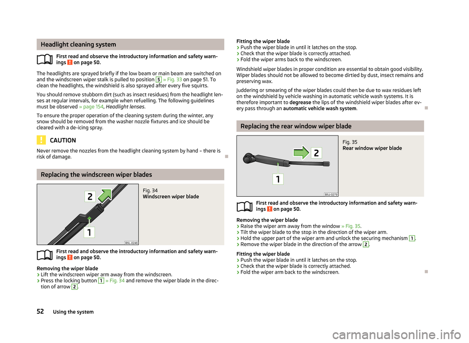
Replacing the windscreen wiper blades
Fig. 34
Windscreen wiper blade
First read and observe the introductory information and safety warn- ings on page 50.
Removing the wiper blade
›
Lift the windscreen wiper arm away from the windscreen.
›
Press the locking button
1
» Fig. 34 and remove the wiper blade in the direc-
tion of arrow
2
.
Fitting the wiper blade›Push the wiper blade in until it latches on the stop.›
Check that the wiper blade is correctly attached.
›
Fold the wiper arms back to the windscreen.
Windshield wiper blades in proper condition are essential to obtain good visibility.
Wiper blades should not be allowed to become dirtied by dust, insect remains and
preserving wax.
Juddering or smearing of the wiper blades could then be due to wax residues left on the windshield by vehicle washing in automatic vehicle wash systems. It is
therefore important to degrease the lips of the windshield wiper blades after ev-
ery pass through an automatic vehicle wash system .
Replacing the rear window wiper blade
Fig. 35
Rear window wiper blade
First read and observe the introductory information and safety warn-
ings on page 50.
Removing the wiper blade
›
Raise the wiper arm away from the window » Fig. 35.
›
Tilt the wiper blade to the stop in the direction of the wiper arm.
›
Hold the upper part of the wiper arm and unlock the securing mechanism
1
.
›
Remove the wiper blade in the direction of the arrow
2
.
Fitting the wiper blade
›
Push the wiper blade in until it latches on the stop.
›
Check that the wiper blade is correctly attached.
›
Fold the wiper arm back to the windscreen.
52Using the system
Page 113 of 223
HeadlightsFirst read and observe the introductory information given on page 109.
The low beam of your headlights is set asymmetrically. It illuminates the side of
the road on which the vehicle is being driven to a greater extent.
When driving in countries in which the traffic drives on the other side of the road
than in your home country, the asymmetrical low beam may dazzle oncoming
drivers. To prevent oncoming traffic from being dazzled, the headlights must be
adjusted by a specialist garage.
Note
For more information on adjusting the headlights, consult a specialist garage.
110Driving
Page 125 of 223

The distribution of the weight is very poor if your vehicle is unladen and the trail-
er is laden. Maintain a particularly low speed if you cannot avoid driving with this
combination.
Tyre pressure
Correct the tyre inflation pressure on your vehicle for a “full load” » page 174,
Tyre service life .
Trailer load
The permissible trailer load must not be exceeded under any circumstan- ces » page 201 , Technical data .
The trailer loads specified apply only to altitudes up to 1 000 metres above mean
sea level.
The engine output falls as altitude increases, as does the ability to climb. There-
fore, for every additional 1000 m in height (or part), the maximum permissible
towed weight must be reduced by 10 %.
The towed weight comprises the actual weights of the (loaded) towing vehicleand the (loaded) trailer.
The trailer and drawbar load information on the type plate of the towing equip- ment are merely test data for the towing equipment. The vehicle-specific values
are detailed in the vehicle documents.WARNING■ Do not exceed the maximum permissible axle and drawbar load and the
maximum permissible total or towed weight of the vehicle and the trailer –
there is the risk of an accident and serious injury.■
Slipping loads can significantly affect the stability and safety of the vehicle/
trailer combination – there is the risk of an accident and serious injury.
Towing a trailer
First read and observe the introductory information and safety warn-
ings
on page 121.
Exterior mirrors
You have to have additional exterior mirrors fitted if you are not able to see the
traffic behind the trailer with the standard rear-view mirrors. National legal re-
quirements must be observed.
Headlights
The front of the vehicle can be lifted when a trailer is being towed and the head-
lights can dazzle other road users.
Adjust the headlight setting on the headlight range control » page 44, Headlight
beam adjustment .
Driving speed
For safety reasons, do not drive faster than 80 km/h when towing a trailer.
Immediately reduce your speed as soon as even the slightest swaying of the trail- er is detected. Never attempt to stop the trailer from “swaying” by accelerating.
Brakes
Apply the brakes in good time! If the trailer is fitted with a trailer brake, apply the
brakes gently at first, then brake firmly. This will avoid brake jolts resulting from
the trailer wheels locking.
On downhill sections shift down a gear in good time to also use the engine as a
brake.
Engine overheating
The speed must be reduced immediately if the needle for the coolant tempera- ture gauge moves into the right-hand area or the red area of the scale.
Stop and switch off the engine if the warning light
in the instrument cluster
starts to flash. Wait a few minutes and check the level of coolant » page 167,
Checking the coolant level .
The following guidelines must be observed » page 22,
Coolant .
The coolant temperature can be reduced by switching on the heating.WARNING■ Adapt your speed to the conditions of the road surface and to the traffic sit-
uation.■
Improper or incorrectly connected electric cables can energise the trailer and
cause functional faults to the vehicle's entire electrical system as well as acci-
dents and severe injuries.
■
Work on the electrical system must only be carried out by specialist garages.
■
Never directly connect the trailer's electrical system with the electrical con-
nections for the tail lights or other current sources.
122Driving
Page 197 of 223

No.Power consumer32High pressure fuel pump, pressure valve33Engine control unit34Engine control unit, vacuum pump35Daytime running lights/radio for vehicles with START-STOP36Main beam37Rear fog light, DC/DC converter START-STOP38Fog lights39Air blower for heating40-41Not assigned42Rear window heater43Horn44Windscreen wipers45Central control unit for convenience system46Engine control unit, fuel pump47Cigarette lighter, power socket in the luggage compartment48ABS, START-STOP (DC/DC) converter ESP49Turn signal lights, brake lights50START-STOP (DC/DC) transformer, radio51Electrical power window (front and rear) - left side52Electrical power window (front and rear) - right side53Parking light = left side, electrical sliding/tilting roof54START-STOP (instrument cluster), alarm55Automatic gearbox control unit56Headlight cleaning system, parking light - right side57Left low beam, headlight range adjustment58Low beam on the right
Fuses in the engine compartmentFig. 152
Vehicle battery: Distribution board cover.
Fig. 153
Schematic representation of
fuse box in engine compartment
First read and observe the introductory information and safety warn-
ings on page 192.
› Press the securing clips on the fuse box cover together at the same time in the
direction of arrow
A
» Fig. 152 and remove the cover in the direction of arrow
B
.
› Release the fixtures in the openings
C
using a flat screwdriver and fold the
cover upwards in direction of arrow
D
.
Fuse assignment in engine compartment
No.Power consumer1Alternator2Not assigned3Interior4Electrical auxiliary heating system 194Do-it-yourself
Page 198 of 223
No.Power consumer5Interior6Glow plugs, radiator fan7Electrohydraulic power steering8ABS or TCS or ESC9Radiator fan10Automatic gearbox11ABS or TCS or ESC12Central control unit13Electrical auxiliary heating system
Note
Fuses 1-7 are replaced by a specialist garage.
Bulbs
Introduction
This chapter contains information on the following subjects:
Headlights
196
Changing the low beam and high beam bulb (halogen headlights)
196
Changing the low beam and high beam bulb (halogen projector headlights)
197
Changing the high beam bulb (halogen projector headlights)
197
Changing the front turn signal bulb
197
Changing the front parking light bulb
197
Foglights and daytime running lights
198
Fabia Scout, Fabia RS foglights
198
Changing the licence plate light bulb
199
Rear light
199
Some manual skills are required to change a bulb. For this reason, if uncertain, we recommend that bulbs are replaced by a specialist garage or other expert help is
sought.
› Switch off the ignition and all of the lights before replacing a bulb.
› Faulty bulbs must only be replaced with the same type of bulbs. The designa-
tion is located on the light socket or the glass bulb.
› A stowage compartment for replacement bulbs is located in a plastic box in the
spare wheel or underneath the floor covering in the boot.WARNING■ Accidents can be caused if the road in front of the vehicle is not sufficiently
illuminated and the vehicle cannot or can only be seen with difficulty by other
road users.■
Always read and observe the warnings before completing any work in the
engine compartment » page 160, Engine compartment .
■
Bulbs H7 and H4 are pressurised and may burst when changed - there is a
risk of injury. We therefore recommended wearing gloves and safety glasses when changing a bulb.
CAUTION
■ Do not take hold of the glass bulb with naked fingers (even the smallest
amount of dirt reduces the working life of the light bulb). Use a clean cloth, nap-
kin, or similar.■
When removing and installing the number plate light and tail light make sure
that the paintwork of the vehicle and the tail light are not damaged.
Note
■ This Owner's Manual only describes the replacement of bulbs where it is possi-
ble to replace the bulbs on your own without any complications arising. Other light bulbs should be changed by your specialist garage.■
We recommend that you always carry a box of replacement bulbs in the vehicle.
Replacement bulbs can be purchased from ŠKODAOriginal Accessories.
■
We recommend that the headlight settings are checked by a specialist garage
after a main beam or low beam bulb has been replaced.
■
Visit a specialist garage if an LED is faulty.
195Fuses and light bulbs
Page 199 of 223

HeadlightsFig. 154
Bulb arrangement: Halogen headlights/halogen projector head-
lights
First read and observe the introductory information and safety warn-ings
on page 195.
Bulb arrangement in the Halogen headlamp
A
- low beam, main beam and side lights
B
- front turn signal light
Bulb arrangement in the Halogen projector headlights
1
- low beam and main beam
2
- parking light and main beam
3
- turn signal lights
Changing the low beam and high beam bulb (halogen
headlights)Fig. 155
Removing bulbs for low and
main beam
First read and observe the introductory information and safety warn-
ings on page 195.
›
Remove the rubber cover
A
» Fig. 154 on page 196.
›
Remove the connector from the bulb, unlock the securing clip and remove the
bulb » Fig. 155 .
›
Insert a new light bulb in such a way that the fixing lugs of the bulb socket fit in
the recesses of the reflector.
›
Lock the circlip and insert the connector in the bulb.
›
Fit the rubber cover
A
.
196Do-it-yourself
Page 200 of 223

Changing the low beam and high beam bulb (halogen projector
headlights)Fig. 156
Removing bulbs for low beam/
low and main beam
First read and observe the introductory information and safety warn-
ings on page 195.
›
Remove the rubber cover
1
» Fig. 154 on page 196.
›
Turn the socket with the bulb to the stop in the direction of the arrow » Fig. 156
and remove it.
›
Replace the bulb, insert the connector and new bulb and turn to the stop in the
opposite direction to that of the arrow.
›
Fit the rubber cover
1
.
Changing the high beam bulb (halogen projector headlights)
Fig. 157
Removing the bulb for the main
beam
First read and observe the introductory information and safety warn-
ings on page 195.
›
Remove the rubber cover
2
» Fig. 154 on page 196.
›Turn the connector with the bulb to the stop in the direction of the ar-
row » Fig. 157 and remove it.›
Replace the bulb, insert the connector and new bulb and turn to the stop in the
opposite direction to that of the arrow.
›
Fit the rubber cover
2
.
Changing the front turn signal bulb
First read and observe the introductory information and safety warn-ings
on page 195.
›
Remove the bulb holder
B
» Fig. 154 on page 196 or the bulb holder
3
to the
stop in an anti-clockwise direction and remove with the bulb for the turn signal.
›
Replace the bulb, insert the bulb holder with the new bulb and turn clockwise
to the stop.
Changing the front parking light bulb
First read and observe the introductory information and safety warn-
ings
on page 195.
›
Remove rubber cover
A
» Fig. 154 on page 196 or
2
.
›
Grasp the lamp holder and remove it from the bulb housing.
›
Replace the light bulb and insert the lamp holder back into the headlamp with
the bulb.
›
Fit the rubber cover.
197Fuses and light bulbs
Page 214 of 223

Car computersee Multifunction display13
Caring for paintwork152
Car park ticket holder71
Carrier67
Central locking button33
Central locking system31
lock33
unlock33
Changing Brake fluid
169
Bulbs195
Bulbs in the rear light199
Engine oil166
Foglight bulb (Scout, RS)198
Foglights and daytime running lights bulbs198
Front parking light bulb197
Front turn signal bulb197
Fuses192
Fuses in the dash panel193
Fuses in the engine compartment194
High beam bulb - halogen projector headlights197
Licence plate light bulb199
Low beam and high beam bulb - halogen head-
lights
196
Low beam and high beam bulb - halogen projec-
tor headlights
197
Wheels181
Changing a wheel Preparation
182
Removing and fitting a wheel182
Subsequent steps183
Charging a vehicle battery171
Check Fit ball head properly
120
Checking Battery electrolyte level
171
Brake fluid168
Coolant level167
Engine oil165
Oil level165
Windscreen washer fluid163
Children and safety140
Child safety Side airbag
142
Child safety lock29
Child safety seat Use of child safety seats
142
Child seat Classification
142
ISOFIX143
on the front passenger seat141
TOP TETHER144
Use of ISOFIX child seats143
Chrome parts refer to Taking care of your vehicle
153
Cigarette lighter70
Cleaning145
Alcantara156
Covers on electrically heated seats157
Fabrics156
Headlight lenses154
Natural leather155
Plastic parts152
Synthetic leather156
Wheels154
Climatronic83
Automatic mode84
Control elements83
Controlling the blower85
Defrosting windscreen85
Recirculated air mode84
Setting the temperature84
Clock12
Clothes hook71
Cockpit 12-volt power outlet
70
Ashtray69
Cigarette lighter70
General view9
Lighting48
Storage compartments72
Compartments72
Computer see Multifunction display
13
Convenience turn signal45
Coolant166
Checking167
Display messages22
Replenishing168
Warning light22
Coolant temperature gauge display
11
Correct seated position125
Driver126
Front passenger126
Notes126
Rear seats126
Counter for distance driven12
Cruise control system114
Cupholders69
D
DAY LIGHT see Daylight running lights
44
Daylight running lights44
De-icing rear window50
Deactivating airbags138
Decorative films153
Delayed locking of the boot lid see Boot lid
37
Diesel refer to Fuel
160
Diesel fuel Operation in winter
160
Diesel particulate filter25
display messages25
Digital clock12
Dipstick165
211Index