2013 RENAULT SCENIC air condition
[x] Cancel search: air conditionPage 91 of 115

37B-91
MR-372-J84-37B000$576.mif
V11
FPA
Vdiag No.: 0C, 04, 08,
0D, 11ELECTRONIC PARKING BRAKE
Fault finding – Conformity check37B
SUB FUNCTION: EMERGENCY BRAKING (CONTINUED 2)
NOTESOnly carry out this conformity check after carrying out a complete check using the
diagnostic tool.
Application conditions: ignition on (forced + after ignition, see Introduction)
Note:
The interpretation of these statuses and parameters is only valid with the
ignition switched on, the statuses and parameters displayed in blue on the
diagnostic tool is information supplied by other computers, which are transmitted via
the multiplex network. If these variables display inconsistent values, check that the
multiplex system test has not shown up any faulty connections. Repair the faulty
multiplex connections before looking for a possible problem with the signals.
Each sub-function in this test is associated with a Fault finding chart.
Special notes:
The diagnostic tool may display the message Computer busy when displaying
statuses and parameters. This message is displayed when the parking brake is
applying or releasing the brake, because the computer gives priority to controlling the
motor before transmitting variables. If this message is displayed, exit the current
screen and then return to it.
Order FunctionParameter or Status
Checked or ActionDisplay and notes Fault finding
4Electronic
parking brakeET011:Parking brakeNo movement of the lever:
INACTIVE
When released: Released
(while releasing, then
INACTIVE)
When applying the brake:
STATUS 1: Static
braking
During emergency
braking:
STATUS 2: Dynamic
braking (over 6 mph
(10 km/h)).
When the system is faulty:
DEFECTIVEIf the status does not function
as indicated, consult the
interpretation of fault DF043
Parking brake motor.
Page 92 of 115

37B-92
MR-372-J84-37B000$576.mif
V11
FPA
Vdiag No.: 0C, 04, 08,
0D, 11ELECTRONIC PARKING BRAKE
Fault finding – Conformity check37B
SUB FUNCTION: EMERGENCY BRAKING (CONTINUED 3)
NOTESOnly carry out this conformity check after carrying out a complete check using the
diagnostic tool.
Application conditions: ignition on (forced + after ignition, see Introduction)
Note:
The interpretation of these statuses and parameters is only valid with the
ignition switched on, the statuses and parameters displayed in blue on the
diagnostic tool is information supplied by other computers, which are transmitted via
the multiplex network. If these variables display inconsistent values, make sure that
the multiplex system test has not shown up any faulty connections. Repair the faulty
multiplex connections before looking for a possible problem with the signals.
Each sub-function in this test is associated with a Fault finding chart.
Special notes
The diagnostic tool may display the message Computer busy when displaying
statuses and parameters. This message is displayed when the parking brake is
applying or releasing the brake, because the computer gives priority to controlling the
motor before transmitting variables. If this message is displayed, exit the current
screen and then return to it.
Order FunctionParameter or Status
Checked or ActionDisplay and notes Fault finding
1Parking brake
assistPR005:Force setting In rest position:
X = 0 N
When applying the brake
on a level surface:
400 < X < 550 N
When fully applied (lever
fully pulled for 2 seconds)
on a level surface:
1100 < X < 1150 N
Note:
depressing the brake
pedal once when the
parking brake is applied
changes the measured
value of the force (change
in the tension of the brake
cables) and the parking
brake may be over-
applied.
Interpretation of these
parameters is only valid
without any pressure
on the brake pedal.The difference between the
reference and measured values
must not be more than - 50 N or
+100N. If the measured value
does not reach or exceeds the
reference value (mechanical or
electrical fault with the control),
the electronic parking brake
computer will detect a fault
(DF025 Vehicle movement
with maximum application,
DF049 Brake application or
DF050 Mechanical jamming).
If one of these three faults is
displayed by the diagnostic tool,
use the relevant interpretation. PR004:Measured force
value
Page 105 of 115

37B-105
MR-372-J84-37B000$936.mif
V11
ELECTRONIC PARKING BRAKE
Fault finding – Fault finding chart
FPA
Vdiag No.: 0C, 04, 08,
0D, 11
37B
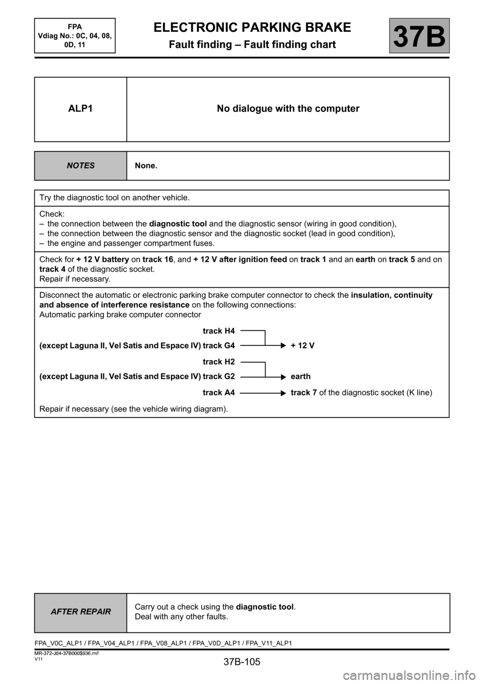
ALP1 No dialogue with the computer
NOTESNone.
Try the diagnostic tool on another vehicle.
Check:
– the connection between the diagnostic tool and the diagnostic sensor (wiring in good condition),
– the connection between the diagnostic sensor and the diagnostic socket (lead in good condition),
– the engine and passenger compartment fuses.
Check for + 12 V battery on track 16, and + 12 V after ignition feed on track 1 and an earth on track 5 and on
track 4 of the diagnostic socket.
Repair if necessary.
Disconnect the automatic or electronic parking brake computer connector to check the insulation, continuity
and absence of interference resistance on the following connections:
Automatic parking brake computer connector
track H4
(except Laguna II, Vel Satis and Espace IV) track G4 + 12 V
track H2
(except Laguna II, Vel Satis and Espace IV) track G2 earth
track A4 track 7 of the diagnostic socket (K line)
Repair if necessary (see the vehicle wiring diagram).
AFTER REPAIRCarry out a check using the diagnostic tool.
Deal with any other faults.
FPA_V0C_ALP1 / FPA_V04_ALP1 / FPA_V08_ALP1 / FPA_V0D_ALP1 / FPA_V11_ALP1
ELECTRONIC PARKING BRAKE
Fault finding – Fault finding chart
MR-372-J84-37B000$936.mif
Page 107 of 115

37B-107
MR-372-J84-37B000$936.mif
V11
ELECTRONIC PARKING BRAKE
Fault finding – Fault finding chart
FPA
Vdiag No.: 0C, 04, 08,
0D, 11
37B
ALP2
CONTINUED 1
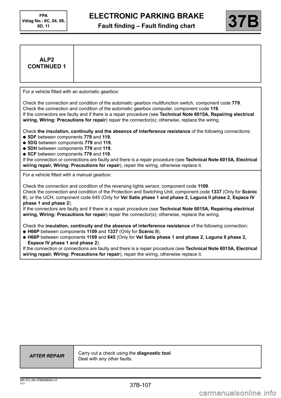
For a vehicle fitted with an automatic gearbox:
Check the connection and condition of the automatic gearbox multifunction switch, component code 779.
Check the connection and condition of the automatic gearbox computer, component code 119.
If the connectors are faulty and if there is a repair procedure (see Technical Note 6015A, Repairing electrical
wiring, Wiring: Precautions for repair) repair the connector(s); otherwise, replace the wiring.
Check the insulation, continuity and the absence of interference resistance of the following connections:
●5DF between components 779 and 119,
●5DG between components 779 and 119,
●5DH between components 779 and 119,
●5CF between components 779 and 119.
If the connection or connections are faulty and there is a repair procedure (see Technical Note 6015A, Electrical
wiring repair, Wiring: Precautions for repair), repair the wiring, otherwise replace it.
For a vehicle fitted with a manual gearbox:
Check the connection and condition of the reversing lights sensor, component code 1109.
Check the connection and condition of the Protection and Switching Unit, component code 1337 (Only for Scénic
II), or the UCH, component code 645 (Only for Vel Satis phase 1 and phase 2, Laguna II phase 2, Espace IV
phase 1 and phase 2).
If the connectors are faulty and if there is a repair procedure (see Technical Note 6015A, Repairing electrical
wiring, Wiring: Precautions for repair) repair the connector(s); otherwise, replace the wiring.
Check the insulation, continuity and the absence of interference resistance of the following connection:
●H66P between components 1109 and 1337 (Only for Scénic II),
●H66P between components 1109 and 645 (Only for Vel Satis phase 1 and phase 2, Laguna II phase 2,
Espace IV phase 1 and phase 2).
If the connection or connections are faulty and there is a repair procedure (see Technical Note 6015A, Electrical
wiring repair, Wiring: Precautions for repair), repair the wiring, otherwise replace it.
AFTER REPAIRCarry out a check using the diagnostic tool.
Deal with any other faults.
Page 110 of 115

37B-110
MR-372-J84-37B000$936.mif
V11
ELECTRONIC PARKING BRAKE
Fault finding – Fault finding chart
FPA
Vdiag No.: 0C, 04, 08,
0D, 11
37B
ALP3
CONTINUED
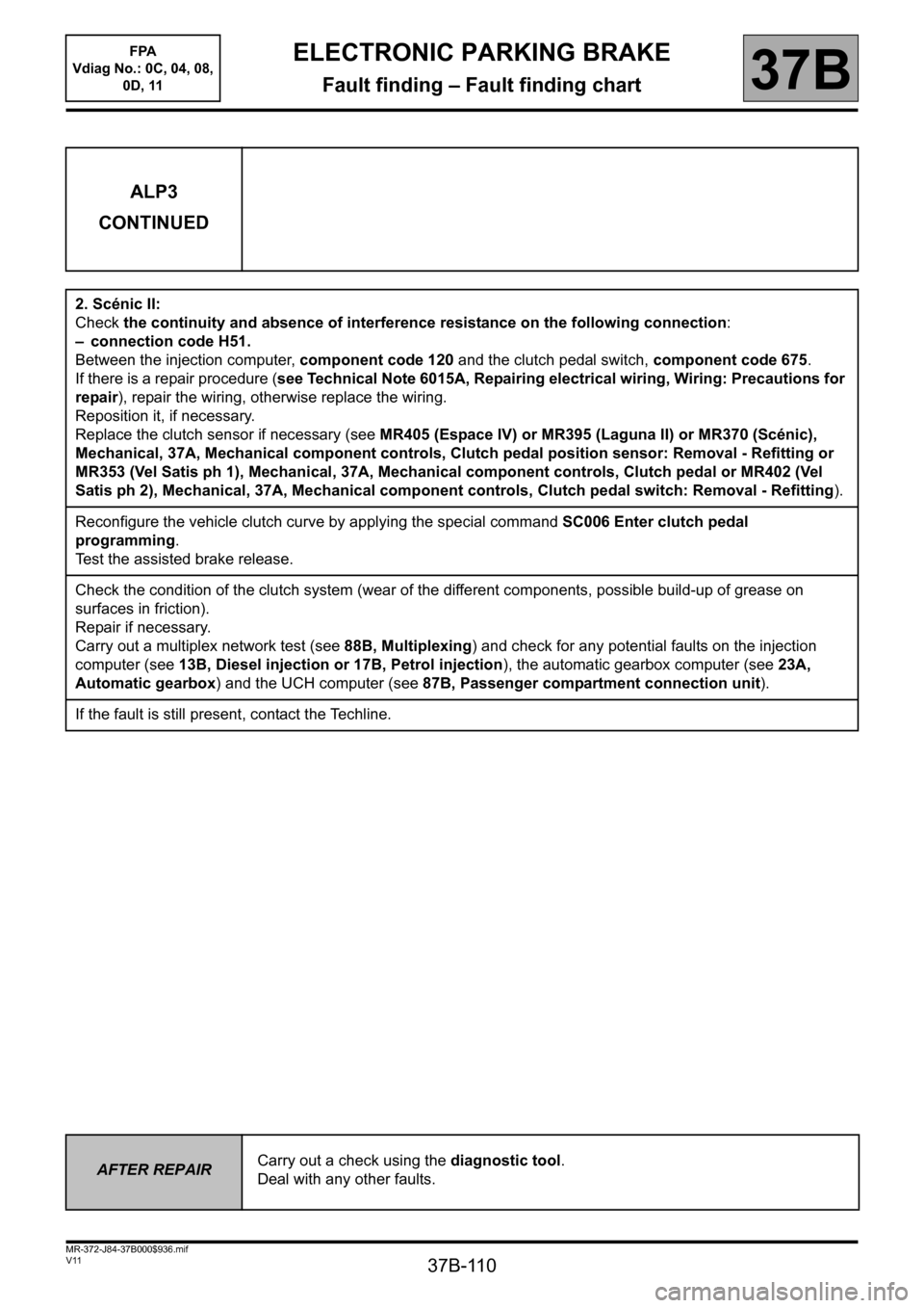
2. Scénic II:
Check the continuity and absence of interference resistance on the following connection:
– connection code H51.
Between the injection computer, component code 120 and the clutch pedal switch, component code 675.
If there is a repair procedure (see Technical Note 6015A, Repairing electrical wiring, Wiring: Precautions for
repair), repair the wiring, otherwise replace the wiring.
Reposition it, if necessary.
Replace the clutch sensor if necessary (see MR405 (Espace IV) or MR395 (Laguna II) or MR370 (Scénic),
Mechanical, 37A, Mechanical component controls, Clutch pedal position sensor: Removal - Refitting or
MR353 (Vel Satis ph 1), Mechanical, 37A, Mechanical component controls, Clutch pedal or MR402 (Vel
Satis ph 2), Mechanical, 37A, Mechanical component controls, Clutch pedal switch: Removal - Refitting).
Reconfigure the vehicle clutch curve by applying the special command SC006 Enter clutch pedal
programming.
Test the assisted brake release.
Check the condition of the clutch system (wear of the different components, possible build-up of grease on
surfaces in friction).
Repair if necessary.
Carry out a multiplex network test (see 88B, Multiplexing) and check for any potential faults on the injection
computer (see 13B, Diesel injection or 17B, Petrol injection), the automatic gearbox computer (see 23A,
Automatic gearbox) and the UCH computer (see 87B, Passenger compartment connection unit).
If the fault is still present, contact the Techline.
AFTER REPAIRCarry out a check using the diagnostic tool.
Deal with any other faults.
Page 115 of 115

37B-115
MR-372-J84-37B000$936.mif
V11
ELECTRONIC PARKING BRAKE
Fault finding – Fault finding chart
FPA
Vdiag No.: 0C, 04, 08,
0D, 11
37B
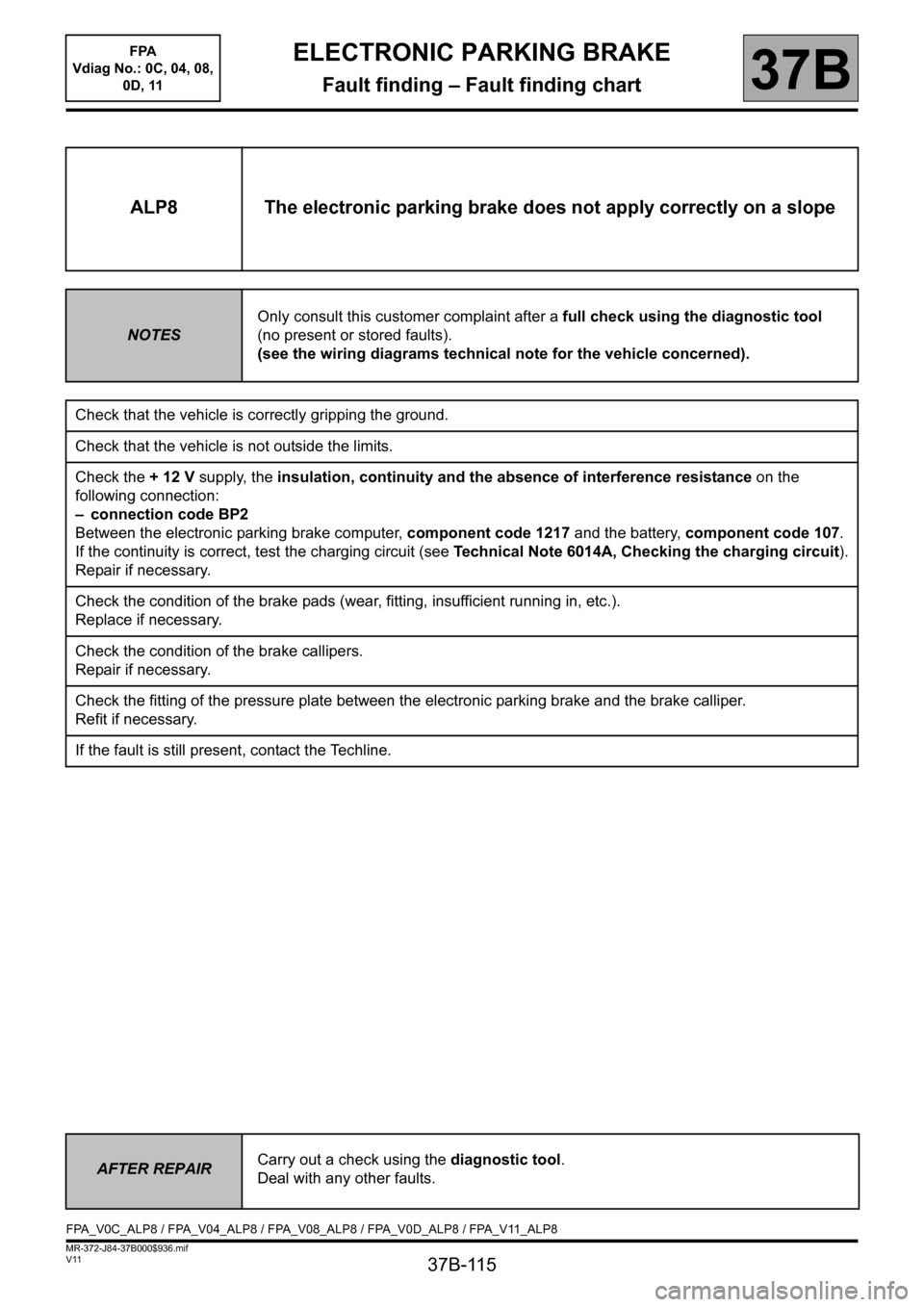
ALP8 The electronic parking brake does not apply correctly on a slope
NOTESOnly consult this customer complaint after a full check using the diagnostic tool
(no present or stored faults).
(see the wiring diagrams technical note for the vehicle concerned).
Check that the vehicle is correctly gripping the ground.
Check that the vehicle is not outside the limits.
Check the + 12 V supply, the insulation, continuity and the absence of interference resistance on the
following connection:
– connection code BP2
Between the electronic parking brake computer, component code 1217 and the battery, component code 107.
If the continuity is correct, test the charging circuit (see Technical Note 6014A, Checking the charging circuit).
Repair if necessary.
Check the condition of the brake pads (wear, fitting, insufficient running in, etc.).
Replace if necessary.
Check the condition of the brake callipers.
Repair if necessary.
Check the fitting of the pressure plate between the electronic parking brake and the brake calliper.
Refit if necessary.
If the fault is still present, contact the Techline.
AFTER REPAIRCarry out a check using the diagnostic tool.
Deal with any other faults.
FPA_V0C_ALP8 / FPA_V04_ALP8 / FPA_V08_ALP8 / FPA_V0D_ALP8 / FPA_V11_ALP8