2013 RENAULT SCENIC diagram
[x] Cancel search: diagramPage 2 of 115

37B-2
MR-372-J84-37B000$072.mif
V11
37B
ELECTRONIC PARKING BRAKE
Fault finding – Introduction
1. SCOPE OF THIS DOCUMENT
This document presents the fault finding procedure applicable to all computers with the following specifications:
2. PREREQUISITES FOR FAULT FINDING
Documentation type
Fault finding procedures (this document):
– Assisted fault finding (integrated into the diagnostic tool), Dialogys.
Wiring Diagrams:
– Visu-Schéma (CD-ROM), paper.
Type of diagnostic tools
–CLIP
Special tooling required
3. REMINDERS
Procedure
To save power, the UCH on the Laguna II Phase 2, Espace IV phase 1, 2 and 4, and Vel Satis phase 1 and 2
interrupts the + after ignition feed supply after 3 minutes.
To run fault finding on a computer, it is possible to force the + after ignition feed for 1 hour by applying the following
procedure:
– Press the card unlocking button,
– Insert the card into the reader,
– press the start button (interrupting the timed + after ignition feed mode),
– press the start button for more than 5 seconds, until the immobiliser warning light flashes rapidly (4 Hz).
This forced + after ignition feed mode remains active for 1 hour.
Pressing the start button or removing the card from the card reader interrupts the forced + after ignition feed, but
does not interrupt the time period for the forced + after ignition feed. Until one hour has elapsed, activating the +
after ignition feed will restart forced + after ignition feed for the remaining time. Vehicle(s): Vel Satis phase 1
Vel Satis phase 2
Laguna II Phase 2
Scénic II Phase 1 and
Scénic II Phase 2
Espace IV phase 1
Espace IV phase 2
Espace IV phase 4
Function concerned: Electronic parking brakeName of computer: FPA
Vdiag No.: 0C, 04, 08, 0D, 11
Special tooling required
Multimeter
Elé. 1681 Universal bornier
FPA_V0C_PRELI/FPA_V04_PRELI/FPA_V08_PRELI/FPA_V0D_PRELI/FPA_V11_PRELI
FPA
Vdiag No.: 0C, 04, 08,
0D, 11
MR-372-J84-37B000$072.mif
Page 19 of 115

37B-19
MR-372-J84-37B000$504.mif
V11
ELECTRONIC PARKING BRAKE
Fault finding – Interpretation of faults
FPA
Vdiag No.: 0C, 04, 08,
0D, 11
37B
DF003
CONTINUED
Disconnect the electronic parking brake computer connector (under the body near the rear axle) to check the
conformity of the power supply (this must equal the voltage measured at the battery terminals ± 0.5 V).
Check the insulation, continuity and the absence of interference resistance on the following connections:
Electronic parking brake computer connector
track H4
(except Laguna II, Vel Satis and Espace IV)
track G4+12V
track H2
(except Laguna II, Vel Satis and Espace IV)
track G2earth
Note:
If the electrical supply is correct, check that the supply has not been cut off by moving the electrical harness
(near to the intermediate connector under the front left-hand seat at the computer connector).
Repair if necessary (see the vehicle wiring diagram).
If the fault persists, contact the Techline.
AFTER REPAIRIf the computer has been replaced (at the request of the Techline), initialise the
electronic parking brake computer (see Replacement of components).
Issue several braking and release commands to confirm the repair.
Deal with any other faults.
Page 24 of 115

37B-24
MR-372-J84-37B000$504.mif
V11
ELECTRONIC PARKING BRAKE
Fault finding – Interpretation of faults
FPA
Vdiag No.: 0C, 04, 08,
0D, 11
37B
DF016
PRESENT
OR
STOREDWARNING LIGHT CIRCUIT
CC.0: Short circuit to earth
CC.1: Short circuit to + 12 V.
NOTESPriorities when dealing with a number of faults:
Deal with faults DF035 Undervoltage, DF055 Battery undervoltage and DF054
Battery voltage too high first, if they are present or stored.
Conditions for applying the fault finding procedure to a stored fault:
The fault is declared present after the forced + after ignition is switched on
(seeIntroduction) and an application request using the control lever.
Special notes:
The fault does not usually come from the electronic parking brake computer.
Note:
After a release request, the fault becomes stored.
Replacing the lever with the parking brake applied may cause this fault. If this fault
appears after replacing the lever, release the parking brake and carry out the
procedure again.
Only for Vdiag 08, 0C and 0D:
If there is a stored fault, refer to the statuses and parameters when it appears.
Explanation of counters: see Introduction section.
If the fault is stored and PR018 = 0 and PR022 > 25 clear the fault: do not take this
fault into account.
If the fault is stored and PR019 < 3, clear the fault: do not take this fault into account.
Check that the electronic parking brake control lever connector is in good condition and also check its clips
(terminals).
Repair if necessary.
Check that there is a 12 V + before ignition supply on track 6 of the electronic parking brake control lever:
see wiring diagram.
Repair if necessary.
Disconnect the electronic parking brake control lever connector in order to check the insulation, continuity and
absence of interference resistance on the following connection:
Electronic parking brake control lever connector:
1216Electronic parking brake computer connector:
1217
Track 5 Track C4
Repair if necessary.
If the fault is still present, replace the parking brake control lever (the indicator light cannot be separated).
If the fault persists, contact the Techline.
AFTER REPAIRIf the computer has been replaced (at the request of the Techline), initialise the
electronic parking brake computer (see Replacement of components).
Issue several braking and release commands to confirm the repair.
Deal with any other faults.
FPA_V0C_DF016/FPA_V04_DF016/FPA_V08_DF016/FPA_V0D_DF016/FPA_V11_DF016
Page 31 of 115

37B-31
MR-372-J84-37B000$504.mif
V11
ELECTRONIC PARKING BRAKE
Fault finding – Interpretation of faults
FPA
Vdiag No.: 0C, 04, 08,
0D, 11
37B
DF035
PRESENT
OR
STOREDUNDERVOLTAGE
1. DEF: Insufficient feed voltage during the command
NOTESPriority in the event of a number of faults:
Deal with fault DF055 Battery undervoltage first if it is present or stored.
Conditions for applying the fault finding procedure to a stored fault:
Apply this fault finding procedure if the fault reappears after the ignition has been
switched off and on again (+ forced after ignition feed: see Introduction) and an
application or release request using the control lever.
Special notes:
This fault is a power supply fault and does not usually stem from the electronic
parking brake computer.
This fault does not indicate computer feed undervoltage but a significant drop in
voltage to the parking brake motor while the command is being issued.
Only for Vdiag 08, 0C and 0D:
If there is a stored fault, refer to the statuses and parameters when it appears.
Explanation of counters: see Introduction.
If the fault is stored and PR018 = 0 and PR022 > 25, clear the fault:
do not take this fault into account.
Disconnect the electronic parking brake computer connector to check the conformity of the supplies and to
check the insulation, continuity and the absence of interference resistance on the following connections:
Electronic parking brake computer connector
track H4
(except Laguna II, Vel Satis and Espace IV)
track G4+12V
track H2
(except Laguna II, Vel Satis and Espace IV)
track G2earth
Repair if necessary (see the vehicle wiring diagram).
Apply the brake and then release it (engine running) to check that during the command the voltage measured at
the fuse does not drop below 10.5 V.
Make the repairs necessary for the parking brake computer electrical supply to be correct (equal to the battery
voltage).
If the fault persists, contact the Techline.
AFTER REPAIRIf the computer has been replaced (at the request of the Techline), initialise the
electronic parking brake computer (see Replacement of components).
Issue several braking and release commands to confirm the repair.
Deal with any other faults.
FPA_V0C_DF035/FPA_V04_DF035/FPA_V08_DF035/FPA_V0D_DF035/FPA_V11_DF035
Page 33 of 115

37B-33
MR-372-J84-37B000$504.mif
V11
ELECTRONIC PARKING BRAKE
Fault finding – Interpretation of faults
FPA
Vdiag No.: 0C, 04, 08,
0D, 11
37B
DF036
CONTINUED
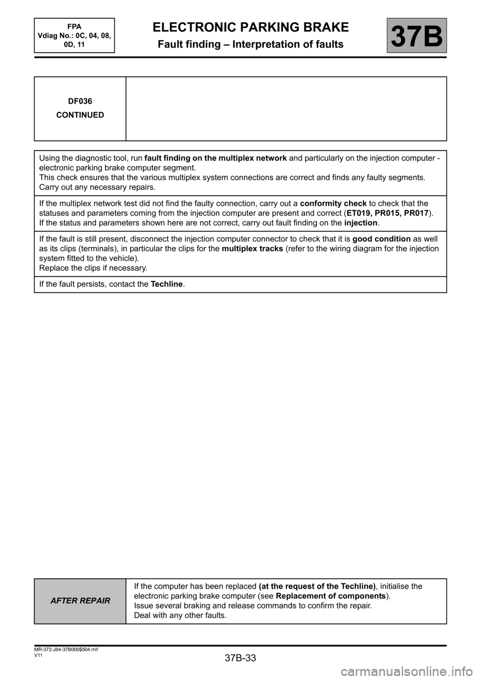
Using the diagnostic tool, run fault finding on the multiplex network and particularly on the injection computer -
electronic parking brake computer segment.
This check ensures that the various multiplex system connections are correct and finds any faulty segments.
Carry out any necessary repairs.
If the multiplex network test did not find the faulty connection, carry out a conformity check to check that the
statuses and parameters coming from the injection computer are present and correct (ET019, PR015, PR017).
If the status and parameters shown here are not correct, carry out fault finding on the injection.
If the fault is still present, disconnect the injection computer connector to check that it is good condition as well
as its clips (terminals), in particular the clips for the multiplex tracks (refer to the wiring diagram for the injection
system fitted to the vehicle).
Replace the clips if necessary.
If the fault persists, contact the Techline.
AFTER REPAIRIf the computer has been replaced (at the request of the Techline), initialise the
electronic parking brake computer (see Replacement of components).
Issue several braking and release commands to confirm the repair.
Deal with any other faults.
Page 35 of 115

37B-35
MR-372-J84-37B000$504.mif
V11
ELECTRONIC PARKING BRAKE
Fault finding – Interpretation of faults
FPA
Vdiag No.: 0C, 04, 08,
0D, 11
37B
DF037
CONTINUED
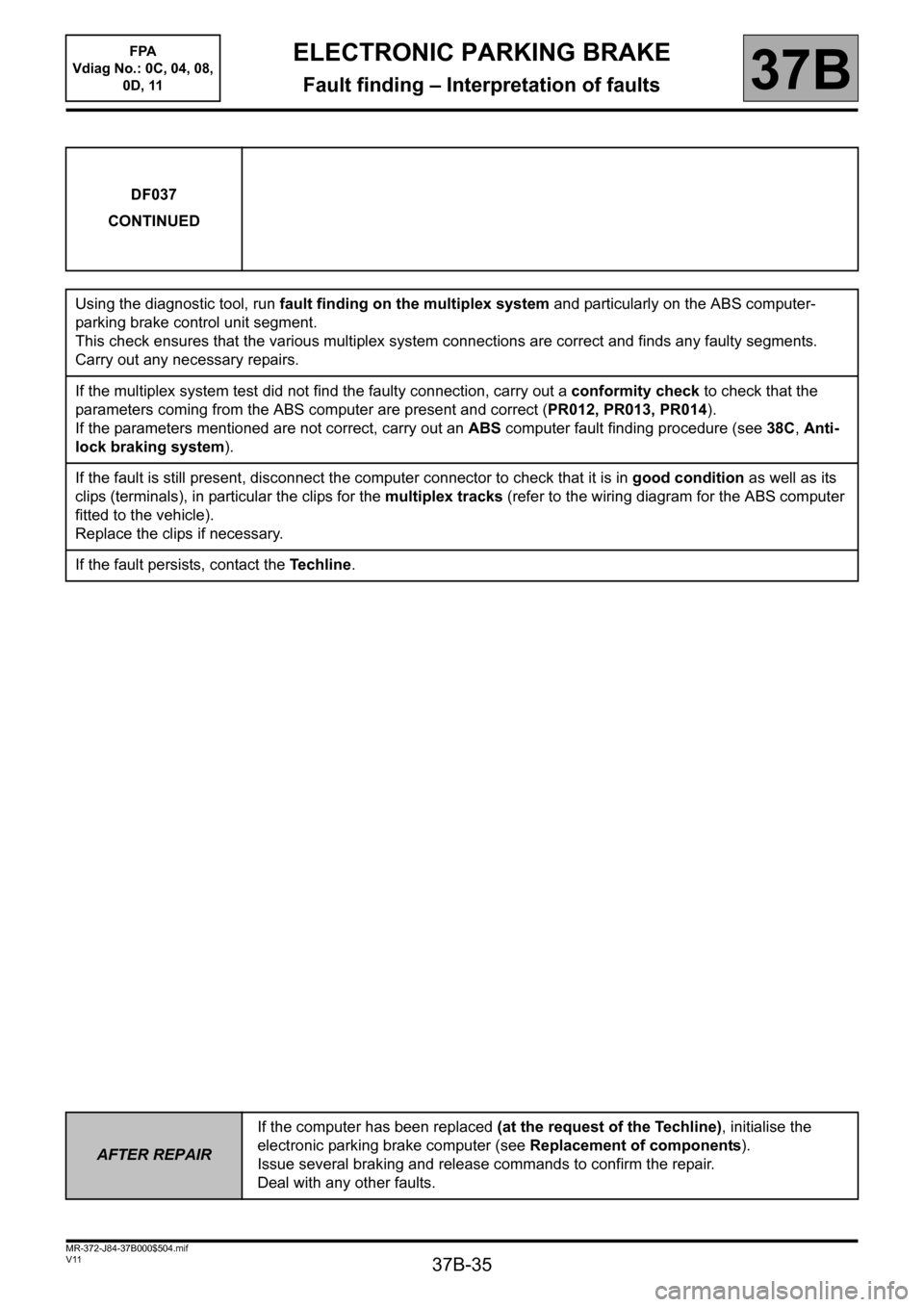
Using the diagnostic tool, run fault finding on the multiplex system and particularly on the ABS computer-
parking brake control unit segment.
This check ensures that the various multiplex system connections are correct and finds any faulty segments.
Carry out any necessary repairs.
If the multiplex system test did not find the faulty connection, carry out a conformity check to check that the
parameters coming from the ABS computer are present and correct (PR012, PR013, PR014).
If the parameters mentioned are not correct, carry out an ABS computer fault finding procedure (see 38C, Anti-
lock braking system).
If the fault is still present, disconnect the computer connector to check that it is in good condition as well as its
clips (terminals), in particular the clips for the multiplex tracks (refer to the wiring diagram for the ABS computer
fitted to the vehicle).
Replace the clips if necessary.
If the fault persists, contact the Techline.
AFTER REPAIRIf the computer has been replaced (at the request of the Techline), initialise the
electronic parking brake computer (see Replacement of components).
Issue several braking and release commands to confirm the repair.
Deal with any other faults.
Page 37 of 115

37B-37
MR-372-J84-37B000$504.mif
V11
ELECTRONIC PARKING BRAKE
Fault finding – Interpretation of faults
FPA
Vdiag No.: 0C, 04, 08,
0D, 11
37B
DF038
CONTINUED
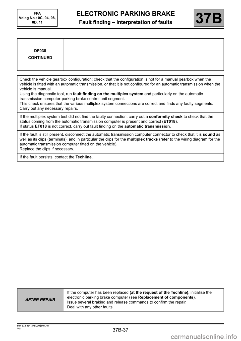
Check the vehicle gearbox configuration: check that the configuration is not for a manual gearbox when the
vehicle is fitted with an automatic transmission, or that it is not configured for an automatic transmission when the
vehicle is manual.
Using the diagnostic tool, run fault finding on the multiplex system and particularly on the automatic
transmission computer-parking brake control unit segment.
This check ensures that the various multiplex system connections are correct and finds any faulty segments.
Carry out any necessary repairs.
If the multiplex system test did not find the faulty connection, carry out a conformity check to check that the
status coming from the automatic transmission computer is present and correct (ET018).
If status ET018 is not correct, carry out fault finding on the automatic transmission.
If the fault is still present, disconnect the automatic transmission computer connector to check that it is sound as
well as its clips (terminals), and in particular the clips for the multiplex tracks (refer to the wiring diagram for the
automatic transmission computer fitted on the vehicle).
Replace the clips if necessary.
If the fault persists, contact the Techline.
AFTER REPAIRIf the computer has been replaced (at the request of the Techline), initialise the
electronic parking brake computer (see Replacement of components).
Issue several braking and release commands to confirm the repair.
Deal with any other faults.
Page 39 of 115

37B-39
MR-372-J84-37B000$504.mif
V11
ELECTRONIC PARKING BRAKE
Fault finding – Interpretation of faults
FPA
Vdiag No.: 0C, 04, 08,
0D, 11
37B
DF039
CONTINUED
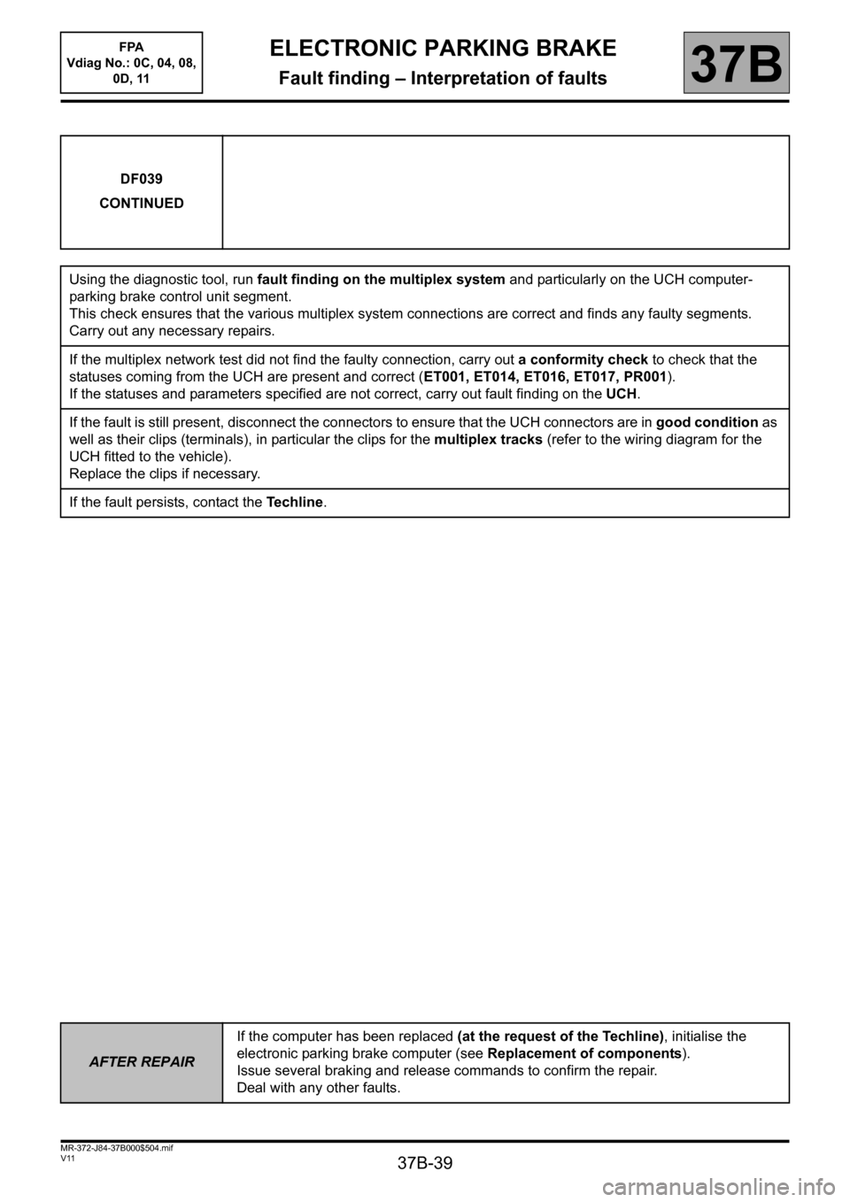
Using the diagnostic tool, run fault finding on the multiplex system and particularly on the UCH computer-
parking brake control unit segment.
This check ensures that the various multiplex system connections are correct and finds any faulty segments.
Carry out any necessary repairs.
If the multiplex network test did not find the faulty connection, carry out a conformity check to check that the
statuses coming from the UCH are present and correct (ET001, ET014, ET016, ET017, PR001).
If the statuses and parameters specified are not correct, carry out fault finding on the UCH.
If the fault is still present, disconnect the connectors to ensure that the UCH connectors are in good condition as
well as their clips (terminals), in particular the clips for the multiplex tracks (refer to the wiring diagram for the
UCH fitted to the vehicle).
Replace the clips if necessary.
If the fault persists, contact the Techline.
AFTER REPAIRIf the computer has been replaced (at the request of the Techline), initialise the
electronic parking brake computer (see Replacement of components).
Issue several braking and release commands to confirm the repair.
Deal with any other faults.