2013 RENAULT SCENIC gearbox
[x] Cancel search: gearboxPage 67 of 115
37B-67
MR-372-J84-37B000$504.mif
V11
ELECTRONIC PARKING BRAKE
Fault finding – Interpretation of faults
FPA
Vdiag No.: 0C, 04, 08,
0D, 11
37B
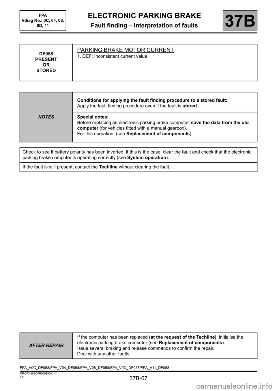
DF058
PRESENT
OR
STOREDPARKING BRAKE MOTOR CURRENT
1. DEF: Inconsistent current value
NOTESConditions for applying the fault finding procedure to a stored fault:
Apply the fault finding procedure even if the fault is stored.
Special notes:
Before replacing an electronic parking brake computer, save the data from the old
computer (for vehicles fitted with a manual gearbox).
For this operation, (see Replacement of components).
Check to see if battery polarity has been inverted, if this is the case, clear the fault and check that the electronic
parking brake computer is operating correctly (see System operation).
If the fault is still present, contact the Techline without clearing the fault.
AFTER REPAIRIf the computer has been replaced (at the request of the Techline), initialise the
electronic parking brake computer (see Replacement of components).
Issue several braking and release commands to confirm the repair.
Deal with any other faults.
FPA_V0C_DF058/FPA_V04_DF058/FPA_V08_DF058/FPA_V0D_DF058/FPA_V11_DF058
Page 69 of 115
37B-69
MR-372-J84-37B000$504.mif
V11
ELECTRONIC PARKING BRAKE
Fault finding – Interpretation of faults37B
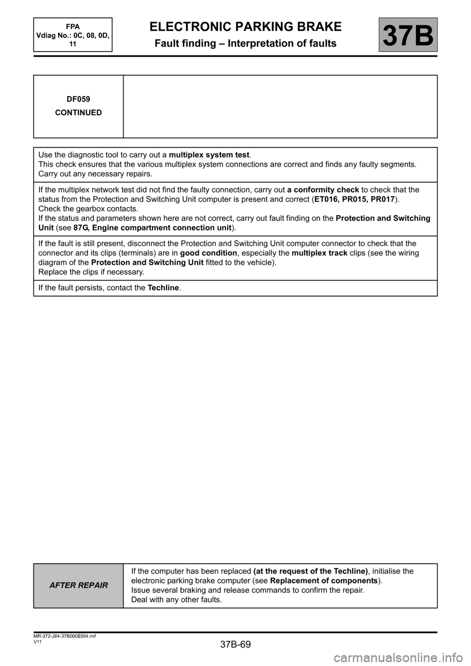
DF059
CONTINUED
Use the diagnostic tool to carry out a multiplex system test.
This check ensures that the various multiplex system connections are correct and finds any faulty segments.
Carry out any necessary repairs.
If the multiplex network test did not find the faulty connection, carry out a conformity check to check that the
status from the Protection and Switching Unit computer is present and correct (ET016, PR015, PR017).
Check the gearbox contacts.
If the status and parameters shown here are not correct, carry out fault finding on the Protection and Switching
Unit (see 87G, Engine compartment connection unit).
If the fault is still present, disconnect the Protection and Switching Unit computer connector to check that the
connector and its clips (terminals) are in good condition, especially the multiplex track clips (see the wiring
diagram of the Protection and Switching Unit fitted to the vehicle).
Replace the clips if necessary.
If the fault persists, contact the Techline.
AFTER REPAIRIf the computer has been replaced (at the request of the Techline), initialise the
electronic parking brake computer (see Replacement of components).
Issue several braking and release commands to confirm the repair.
Deal with any other faults.
FPA
Vdiag No.: 0C, 08, 0D,
11
Page 70 of 115
37B-70
MR-372-J84-37B000$504.mif
V11
ELECTRONIC PARKING BRAKE
Fault finding – Interpretation of faults
FPA
Vdiag No.: 0C, 04, 08,
0D, 11
37B
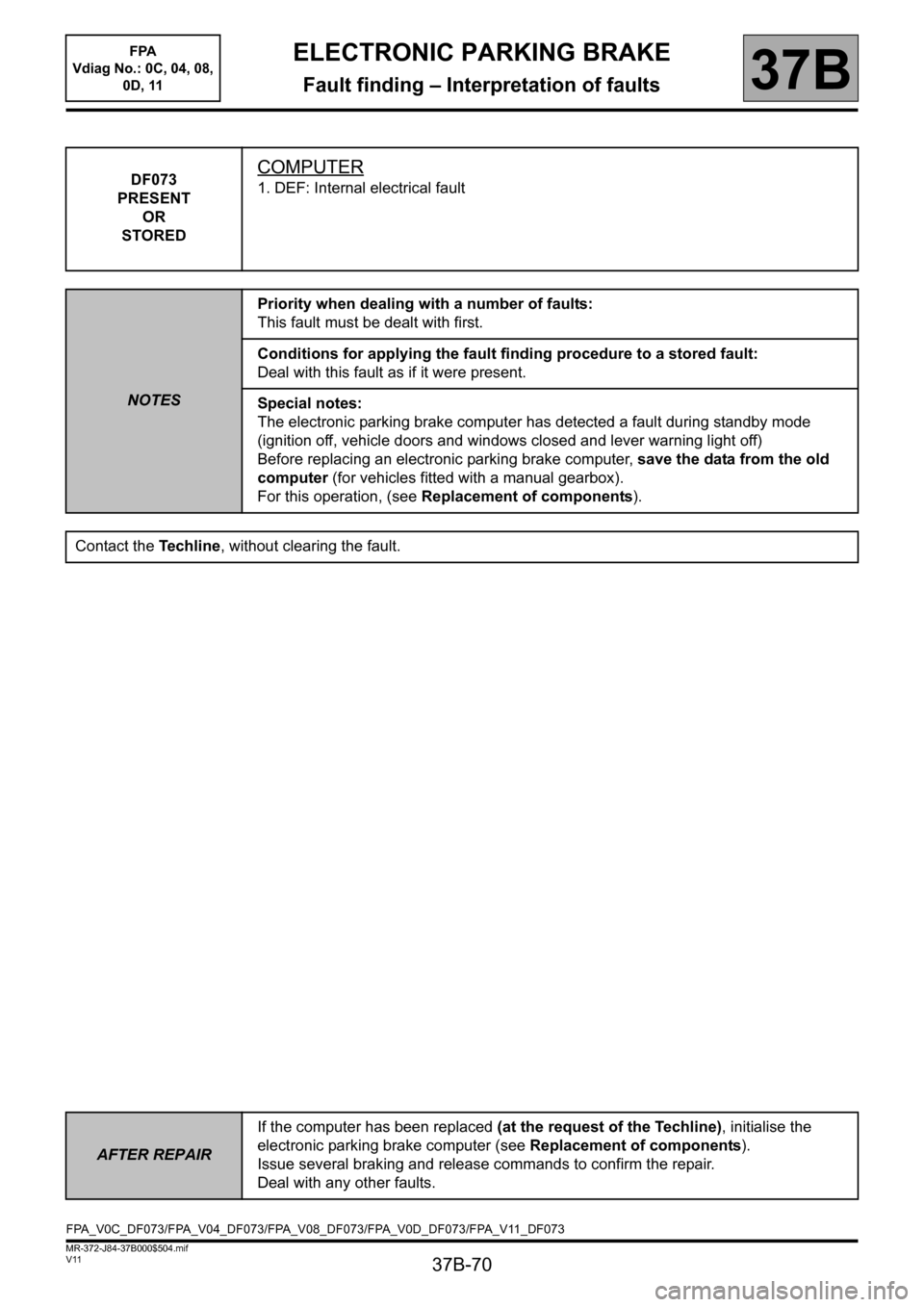
DF073
PRESENT
OR
STOREDCOMPUTER
1. DEF: Internal electrical fault
NOTESPriority when dealing with a number of faults:
This fault must be dealt with first.
Conditions for applying the fault finding procedure to a stored fault:
Deal with this fault as if it were present.
Special notes:
The electronic parking brake computer has detected a fault during standby mode
(ignition off, vehicle doors and windows closed and lever warning light off)
Before replacing an electronic parking brake computer, save the data from the old
computer (for vehicles fitted with a manual gearbox).
For this operation, (see Replacement of components).
Contact the Techline, without clearing the fault.
AFTER REPAIRIf the computer has been replaced (at the request of the Techline), initialise the
electronic parking brake computer (see Replacement of components).
Issue several braking and release commands to confirm the repair.
Deal with any other faults.
FPA_V0C_DF073/FPA_V04_DF073/FPA_V08_DF073/FPA_V0D_DF073/FPA_V11_DF073
Page 82 of 115
37B-82
MR-372-J84-37B000$576.mif
V11
FPA
Vdiag No.: 0C, 04, 08,
0D, 11ELECTRONIC PARKING BRAKE
Fault finding – Conformity check37B
SUB-FUNCTION: AUTOMATIC RELEASE (CONTINUED 1)
NOTESOnly carry out this conformity check after carrying out a complete check using the
diagnostic tool.
Application conditions: ignition on (forced + after ignition, see Introduction)
Note:
The interpretation of these statuses and parameters is only valid with the
ignition switched on, the statuses and parameters displayed in blue on the
diagnostic tool is information supplied by other computers, which are transmitted via
the multiplex network. If these variables display inconsistent values, check that the
multiplex system test has not shown up any faulty connections. Repair the faulty
multiplex connections before looking for a possible problem with the signals.
Each sub-function in this test is associated with a Fault finding chart.
Special notes
The diagnostic tool may display the message Computer busy when displaying
statuses and parameters. This message is displayed when the parking brake is
applying or releasing the brake, because the computer gives priority to controlling the
motor before transmitting variables. If this message is displayed, exit the current
screen and then return to it.
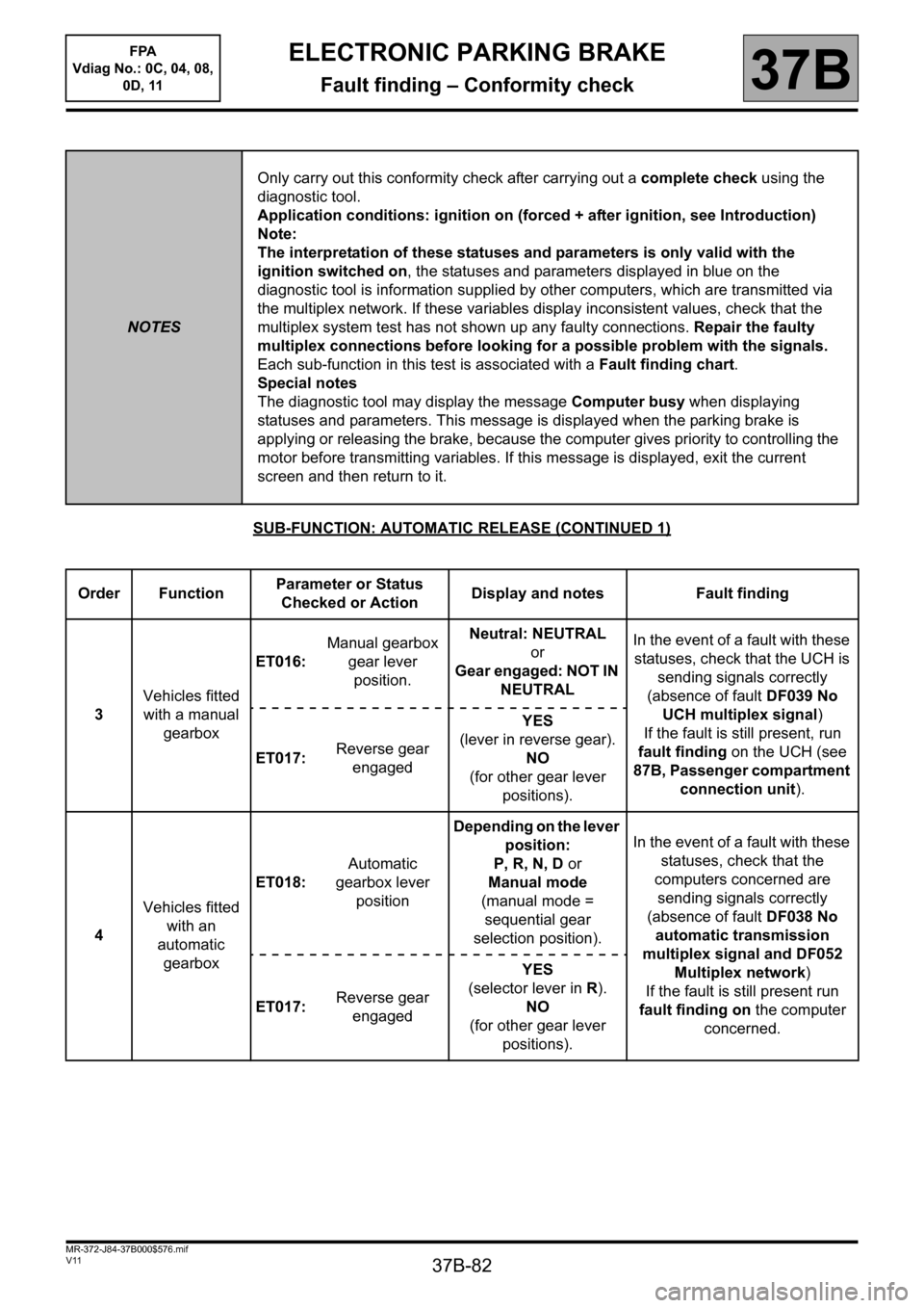
Order FunctionParameter or Status
Checked or ActionDisplay and notes Fault finding
3Vehicles fitted
with a manual
gearboxET016:Manual gearbox
gear lever
position.Neutral: NEUTRAL
or
Gear engaged: NOT IN
NEUTRALIn the event of a fault with these
statuses, check that the UCH is
sending signals correctly
(absence of fault DF039 No
UCH multiplex signal)
If the fault is still present, run
fault finding on the UCH (see
87B, Passenger compartment
connection unit). ET017:Reverse gear
engagedYES
(lever in reverse gear).
NO
(for other gear lever
positions).
4Vehicles fitted
with an
automatic
gearboxET018:Automatic
gearbox lever
positionDepending on the lever
position:
P, R, N, D or
Manual mode
(manual mode =
sequential gear
selection position).In the event of a fault with these
statuses, check that the
computers concerned are
sending signals correctly
(absence of fault DF038 No
automatic transmission
multiplex signal and DF052
Multiplex network)
If the fault is still present run
fault finding on the computer
concerned. ET017:Reverse gear
engagedYES
(selector lever in R).
NO
(for other gear lever
positions).
Page 93 of 115

37B-93
MR-372-J84-37B000$648.mif
V11
ELECTRONIC PARKING BRAKE
Fault finding – Status summary table
FPA
Vdiag No.: 0C, 04, 08,
0D, 11
37B
Tool status Diagnostic tool title
ET001+ After ignition supply
ET008Manual control: brake application switch
ET009Redundant braking switch position
ET010Manual control: brake releasing switch
ET011Parking brake
ET014Door opening switches
ET016Manual gearbox lever position
ET017Reverse gear engaged
ET018Automatic gearbox lever position
ET019Engine
ET022Automatic braking configuration
ET024System operation
ELECTRONIC PARKING BRAKE
Fault finding – Status summary table
MR-372-J84-37B000$648.mif
Page 101 of 115

37B-101
MR-372-J84-37B000$792.mif
V11
ELECTRONIC PARKING BRAKE
Fault finding – Interpretation of commands
FPA
Vdiag No.: 0C, 04, 08,
0D, 11
37B
SC005
SAVE CLUTCH PEDAL PROGRAMMING
NOTESSpecial notes:
The commands are found in the tool's repair mode, Programming button.
Run command SC005 Backup clutch pedal programming with the electronic parking brake computer which is
faulty or to be replaced.
The pedals and the gearbox must not be operated during the backup procedure.
Carrying out this backup procedure before each replacement of the computer enables the old clutch pedal travel
specifications to be re-entered into the new electronic parking brake computer.
Park the vehicle on a level surface.
– Select the diagnostic tool's Repair mode menu.
– From the tool's navigation menu, select Programming.
Run command SC005 Backup clutch pedal programming.
AFTER REPAIRRepeat the conformity check from the start.
Page 106 of 115
37B-106
MR-372-J84-37B000$936.mif
V11
ELECTRONIC PARKING BRAKE
Fault finding – Fault finding chart
FPA
Vdiag No.: 0C, 04, 08,
0D, 11
37B
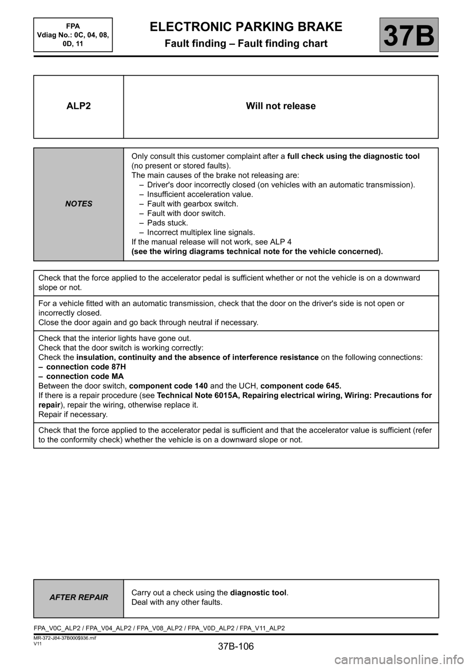
ALP2 Will not release
NOTESOnly consult this customer complaint after a full check using the diagnostic tool
(no present or stored faults).
The main causes of the brake not releasing are:
– Driver's door incorrectly closed (on vehicles with an automatic transmission).
– Insufficient acceleration value.
– Fault with gearbox switch.
– Fault with door switch.
– Pads stuck.
– Incorrect multiplex line signals.
If the manual release will not work, see ALP 4
(see the wiring diagrams technical note for the vehicle concerned).
Check that the force applied to the accelerator pedal is sufficient whether or not the vehicle is on a downward
slope or not.
For a vehicle fitted with an automatic transmission, check that the door on the driver's side is not open or
incorrectly closed.
Close the door again and go back through neutral if necessary.
Check that the interior lights have gone out.
Check that the door switch is working correctly:
Check the insulation, continuity and the absence of interference resistance on the following connections:
– connection code 87H
– connection code MA
Between the door switch, component code 140 and the UCH, component code 645.
If there is a repair procedure (see Technical Note 6015A, Repairing electrical wiring, Wiring: Precautions for
repair), repair the wiring, otherwise replace it.
Repair if necessary.
Check that the force applied to the accelerator pedal is sufficient and that the accelerator value is sufficient (refer
to the conformity check) whether the vehicle is on a downward slope or not.
AFTER REPAIRCarry out a check using the diagnostic tool.
Deal with any other faults.
FPA_V0C_ALP2 / FPA_V04_ALP2 / FPA_V08_ALP2 / FPA_V0D_ALP2 / FPA_V11_ALP2
Page 107 of 115
37B-107
MR-372-J84-37B000$936.mif
V11
ELECTRONIC PARKING BRAKE
Fault finding – Fault finding chart
FPA
Vdiag No.: 0C, 04, 08,
0D, 11
37B
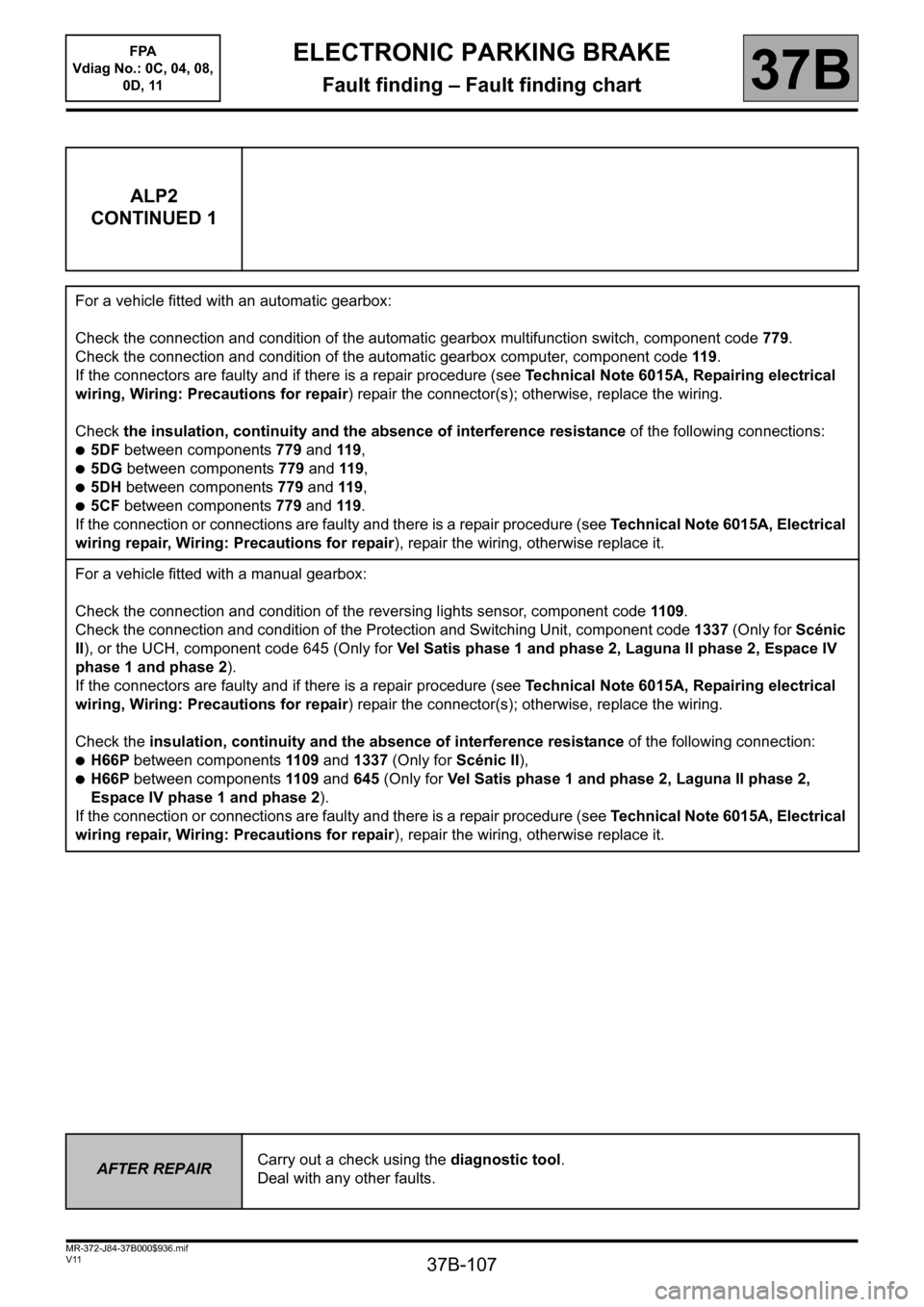
ALP2
CONTINUED 1
For a vehicle fitted with an automatic gearbox:
Check the connection and condition of the automatic gearbox multifunction switch, component code 779.
Check the connection and condition of the automatic gearbox computer, component code 119.
If the connectors are faulty and if there is a repair procedure (see Technical Note 6015A, Repairing electrical
wiring, Wiring: Precautions for repair) repair the connector(s); otherwise, replace the wiring.
Check the insulation, continuity and the absence of interference resistance of the following connections:
●5DF between components 779 and 119,
●5DG between components 779 and 119,
●5DH between components 779 and 119,
●5CF between components 779 and 119.
If the connection or connections are faulty and there is a repair procedure (see Technical Note 6015A, Electrical
wiring repair, Wiring: Precautions for repair), repair the wiring, otherwise replace it.
For a vehicle fitted with a manual gearbox:
Check the connection and condition of the reversing lights sensor, component code 1109.
Check the connection and condition of the Protection and Switching Unit, component code 1337 (Only for Scénic
II), or the UCH, component code 645 (Only for Vel Satis phase 1 and phase 2, Laguna II phase 2, Espace IV
phase 1 and phase 2).
If the connectors are faulty and if there is a repair procedure (see Technical Note 6015A, Repairing electrical
wiring, Wiring: Precautions for repair) repair the connector(s); otherwise, replace the wiring.
Check the insulation, continuity and the absence of interference resistance of the following connection:
●H66P between components 1109 and 1337 (Only for Scénic II),
●H66P between components 1109 and 645 (Only for Vel Satis phase 1 and phase 2, Laguna II phase 2,
Espace IV phase 1 and phase 2).
If the connection or connections are faulty and there is a repair procedure (see Technical Note 6015A, Electrical
wiring repair, Wiring: Precautions for repair), repair the wiring, otherwise replace it.
AFTER REPAIRCarry out a check using the diagnostic tool.
Deal with any other faults.