2013 RENAULT KANGOO fuel cap
[x] Cancel search: fuel capPage 12 of 204

13B-12V1 MR-376-X76-13B000$030.mif
DIESEL INJECTION
Fault finding – System operation13B
DCM 1.2 Injection
Program no.: 4C
Vdiag No.: 08
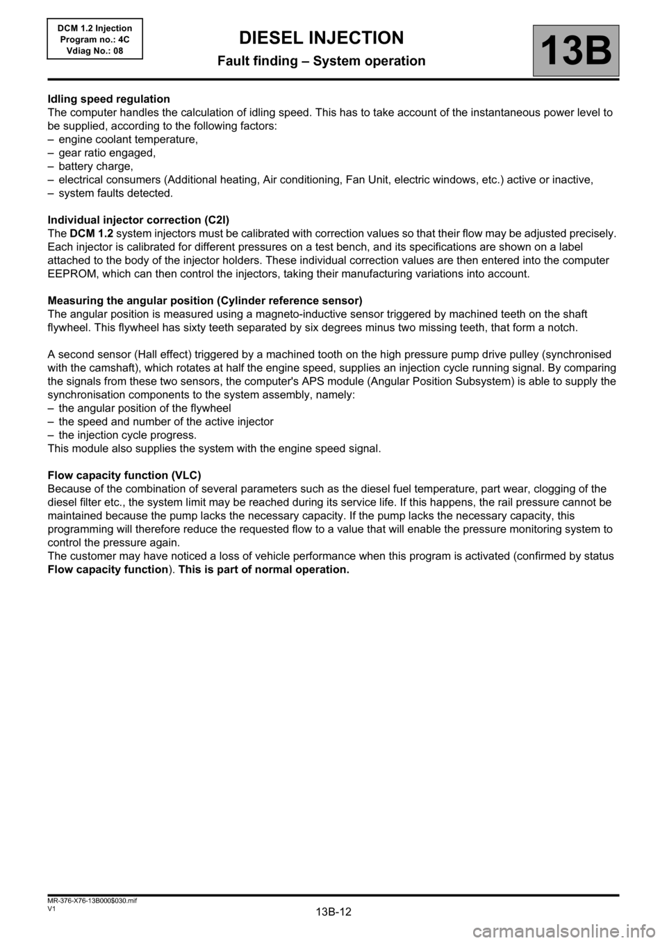
Idling speed regulation
The computer handles the calculation of idling speed. This has to take account of the instantaneous power level to
be supplied, according to the following factors:
– engine coolant temperature,
– gear ratio engaged,
– battery charge,
– electrical consumers (Additional heating, Air conditioning, Fan Unit, electric windows, etc.) active or inactive,
– system faults detected.
Individual injector correction (C2I)
The DCM 1.2 system injectors must be calibrated with correction values so that their flow may be adjusted precisely.
Each injector is calibrated for different pressures on a test bench, and its specifications are shown on a label
attached to the body of the injector holders. These individual correction values are then entered into the computer
EEPROM, which can then control the injectors, taking their manufacturing variations into account.
Measuring the angular position (Cylinder reference sensor)
The angular position is measured using a magneto-inductive sensor triggered by machined teeth on the shaft
flywheel. This flywheel has sixty teeth separated by six degrees minus two missing teeth, that form a notch.
A second sensor (Hall effect) triggered by a machined tooth on the high pressure pump drive pulley (synchronised
with the camshaft), which rotates at half the engine speed, supplies an injection cycle running signal. By comparing
the signals from these two sensors, the computer's APS module (Angular Position Subsystem) is able to supply the
synchronisation components to the system assembly, namely:
– the angular position of the flywheel
– the speed and number of the active injector
– the injection cycle progress.
This module also supplies the system with the engine speed signal.
Flow capacity function (VLC)
Because of the combination of several parameters such as the diesel fuel temperature, part wear, clogging of the
diesel filter etc., the system limit may be reached during its service life. If this happens, the rail pressure cannot be
maintained because the pump lacks the necessary capacity. If the pump lacks the necessary capacity, this
programming will therefore reduce the requested flow to a value that will enable the pressure monitoring system to
control the pressure again.
The customer may have noticed a loss of vehicle performance when this program is activated (confirmed by status
Flow capacity function). This is part of normal operation.
Page 23 of 204

13B-23V1 MR-376-X76-13B000$060.mif
DIESEL INJECTION
Fault finding – Fault summary table13B
DCM 1.2 Injection
Program no.: 4C
Vdiag No.: 08
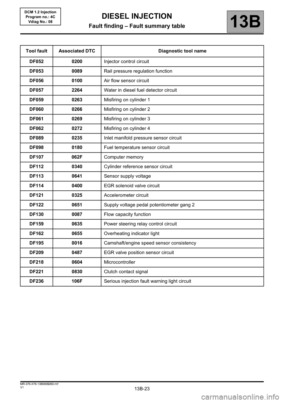
Tool fault Associated DTC Diagnostic tool name
DF052 0200Injector control circuit
DF053 0089Rail pressure regulation function
DF056 0100Air flow sensor circuit
DF057 2264Water in diesel fuel detector circuit
DF059 0263Misfiring on cylinder 1
DF060 0266Misfiring on cylinder 2
DF061 0269Misfiring on cylinder 3
DF062 0272Misfiring on cylinder 4
DF089 0235Inlet manifold pressure sensor circuit
DF098 0180Fuel temperature sensor circuit
DF107 062FComputer memory
DF112 0340Cylinder reference sensor circuit
DF113 0641Sensor supply voltage
DF114 0400EGR solenoid valve circuit
DF121 0325Accelerometer circuit
DF122 0651Supply voltage pedal potentiometer gang 2
DF130 0087Flow capacity function
DF159 0635Power steering relay control circuit
DF162 0655Overheating indicator light
DF195 0016Camshaft/engine speed sensor consistency
DF209 0487EGR valve position sensor circuit
DF218 0604Microcontroller
DF221 0830Clutch contact signal
DF236 106FSerious injection fault warning light circuit
Page 99 of 204

13B-99
AFTER
REPAIRDeal with any faults declared by the diagnostic tool.
Clear the computer memory.
Carry out a road test followed by another check with the diagnostic tool.
V1 MR-376-X76-13B000$072.mif
DIESEL INJECTION
Fault finding – Interpretation of faults13B
DCM 1.2 Injection
Program no.: 4C
Vdiag No.: 08
DF130
PRESENT
OR
STOREDFLOW CAPACITY FUNCTION
1.DEF: High flow capacity < minimum
2.DEF: High flow capacity > maximum
NOTESSpecial notes:
If the fault DF130 is present, the engine may stop and the level 2 warning light comes
on.
Conditions for applying the fault finding procedure to a stored fault:
The fault is considered present when the engine is running.
Use the Wiring Diagrams Technical Note for Logan, Sandero, Duster, Thalia 2/
Symbol 2 or Kangoo VLL.
Check the connection and condition of the flow actuator (IMV) connector, component code 1105.
Check the connection and condition of the injection computer connector, component code 120.
If the connectors are faulty and if there is a repair procedure (see Technical Note 6015A (Renault) or Technical
Note 9804A (Dacia), Electrical wiring repair, Wiring: Precautions for repair), repair the connector, otherwise
replace the wiring.
Check the insulation, continuity and the absence of interference resistance on the following connection:
●3HI between components 120 and 1105.
If the connection is faulty and if there is a repair procedure (see Technical Note 6015A (Renault) or Technical
Note 9804A (Dacia), Electrical wiring repair, Wiring: Precautions for repair), repair the wiring, otherwise
replace it.
Measure the resistance between connections 3HI and 3FB (or 3FB2) of the flow actuator, component code 1105.
If the resistance of the flow actuator is not between: 4.8 < X < 5.8 at 20°C, replace the flow actuator (see MR
388 (Logan/Sandero), MR 451 (Duster), MR 423 (Thalia 2/Symbol 2) or MR 374 (Kangoo VLL), Mechanical,
13B, Diesel injection, Flow actuator: Removal – Refitting).
Check the presence and conformity of fuel in the tank.
Apply test 13 Diesel fuel conformity check.
Run test 1 Low pressure circuit check.
If the fault is still present, run test 6 High pressure system check.
DCM1.2_V08_DF130
Page 135 of 204

13B-135V1 MR-376-X76-13B000$090.mif
13B
DCM 1.2 Injection
Program no.: 4C
Vdiag No.: 08
Tool Status Diagnostic tool title
ET003Engine immobiliser
ET007Pre-postheating control
ET008EGR solenoid valve control (not applicable to K9K796 Euro 2)
ET023Fast idle speed request
ET038Engine
ET039Brake pedal
ET116Climate control authorisation
ET122Brake switch no. 1 signal
ET123Brake switch no. 2 signal
ET164Configuration with air conditioning
ET200Fuel flow controller
ET227Key
ET233Clutch pedal
ET432Wastegate regulation
ET563Flow capacity function
ET637New pump chamber filling
DIESEL INJECTION
Fault finding – Status summary table
Page 168 of 204

13B-168
AFTER REPAIRCarry out a road test followed by a check with the diagnostic tool.
V1 MR-376-X76-13B000$150.mif
DIESEL INJECTION
Fault finding – Fault Finding Chart13B
DCM 1.2 Injection
Program no.: 4C
Vdiag No.: 08
ALP10 Engine hesitation
NOTESSpecial note:
Only consult this customer complaint after a complete check using the diagnostic tool
(see System operation, Function: Fuel supply management (advance, flow and
pressure), paragraph: flow capacity function (VLC)).
Check that the fuel tank is filled and that the appropriate fuel is used.
Apply TEST 13 Diesel fuel conformity check.
Check the low pressure circuit by running TEST 1 Low pressure circuit check.
Using the diagnostic tool, check that the injector codes (C2I) are correctly entered on the identification screen. If
not, configure the correct injector codes using command SC002 Enter injector codes
Is the engine wiring harness cut or pinched? Carry out the necessary repairs.
Is the compression in order? Carry out the necessary repairs.
Is the valve clearance set correctly? Carry out the necessary repairs.
Check the high pressure pump by running TEST 6 High pressure system check.
YES
NO
NO
YES
NO
YES
A
DCM1.2_V08_ALP10
Page 169 of 204

13B-169
AFTER REPAIRCarry out a road test followed by a check with the diagnostic tool.
V1 MR-376-X76-13B000$150.mif
DIESEL INJECTION
Fault finding – Fault Finding Chart13B
DCM 1.2 Injection
Program no.: 4C
Vdiag No.: 08
ALP10
CONTINUED
Is status ET563 Flow capacity function
"ACTIVE"?The vehicle has entered the "Flow capacity
function" program. This function is activated
more easily when: the external temperature is
high, the fuel level in the tank is at 1/4, the
vehicle is laden and if the vehicle speed is high.
Check the condition of the computer connections
(for bent pins, signs of oxidation, silicone, etc.) and
check that the computer connectors lock correctly.Check the diesel filter.
Is it close to the replacement mileage?
Contact the Techline if the customer complaint is
still present.
Replace the diesel filter (see MR 388 (Logan/
Sandero), MR 451 (Duster), MR 423 (Thalia 2/
Symbol 2) or MR 374 (Kangoo VLL),
Mechanical, 13A, Fuel supply, Fuel filter:
Removal - Refitting).
Contact the Techline if the customer complaint is
still present.
A
YES
NO
YES
Page 170 of 204

13B-170
AFTER REPAIRCarry out a road test followed by a check with the diagnostic tool.
V1 MR-376-X76-13B000$150.mif
DIESEL INJECTION
Fault finding – Fault Finding Chart13B
DCM 1.2 Injection
Program no.: 4C
Vdiag No.: 08
ALP11 Loss of power
NOTESSpecial note:
Only address this customer complaint after a complete check with the diagnostic
tool.
See explanation for flow capacity function in system operation.
Is status ET563 Flow capacity function "ACTIVE"?
Using the diagnostic tool, check that the
injector codes (C2I) are correctly
entered on the identification screen. If not,
configure the correct injector codes using
command SC002 Enter injector codesCheck the diesel filter.
Is it close to the replacement mileage?
Replace the diesel filter (see MR 388 (Logan/Sandero),
MR 451 (Duster), MR 423 (Thalia 2/Symbol 2) or MR
374 (Kangoo VLL), Mechanical, 13A, Fuel supply, Fuel
filter: Removal - Refitting).
Check the air inlet circuit by running TEST 5 Inlet circuit check.
Is the engine oil level correct? Top up the oil level.
NOYES
NO
YES
NO
A
YES
DCM1.2_V08_ALP11
Page 191 of 204

13B-191V1 MR-376-X76-13B000$160.mif
DIESEL INJECTION
Fault finding – Tests13B
DCM 1.2 Injection
Program no.: 4C
Vdiag No.: 08
TEST 6 High pressure system check
NOTESSpecial note:
Certain faults make it impossible to carry out this test - deal with these first.
WARNING
Running the starter motor for more than 5 seconds is dangerous and serves no useful
purpose.
Preliminary Checks:
– Check for the presence of fuel
– Check that there is no air in the low pressure circuit. Apply TEST 1 Low pressure circuit check.
– Ensure that the correct fuel is being used. Apply TEST 13 Diesel fuel conformity check.
The pump's capacity to produce high pressure can be checked by the following procedure:
–With the ignition off, disconnect the low pressure actuator from the pump (IMV brown connector) and
connect a test IMV or the MOT adapter. 1711 adapter.
– Electrically disconnect the four injectors.
– Switch on the ignition, connect the diagnostic tool and re-establish dialogue with the injection system.
– Go to the Main computer statuses and parameters screen.
– Run the test cold, PR064 "Coolant temperature" < 30 °C or equal to ambient temperature.
–Activate the starter for 5 seconds.
– Read the maximum rail pressure value PR038 Rail pressure during the test on the diagnostic tool.
PR038 > 1050 bar?
A
NO
B
YES
DCM1.2_V08_TEST06