Page 21 of 35

Downloaded from www.Manualslib.com manuals search engine 98CUP_2013 Release
C-21
B.6.3.4.2 SECONDARY ALARMS (CATEGORY B)
All non Cat A alarms are classified in the category B. They are clearly displayed to the
driver, but he is still able to drive normally (the dashboard information remains normally
readable).
A message is displayed in the Area “Default”
In addition with the message displayed, the corresp onding alarm LED becomes ORANGE:
- 1 Right HS column (gearbox diagnostic)
- 1 Left HS column (engine diagnostic)
If 1 or more alarms are present, the messages are s crolling in the “default” area
B.6.3.4.3 A
LARMS AND THRESHOLD
Category Message Alarm LED Meaning Threshold
A “V BAT MIN”
+ value in Red 4 LEFT + 3 RIGHT Min. battery voltage
V batt < 11V and
revs > 4000 rpm
B “V BAT MAX”
+ value in Orange 1 Left Max. battery voltage V batt > 15V
B “OILP max”
+ value in Orange 1 Left Max. oil pressure Oil P > 6 bar
A “OILP min”
+ value in Red 4 LEFT + 3 RIGHT Min. oil pressure Oil P < 1.5 bar and
revs > 3000rpm
A “Water T Max”
+ value in Red 4 LEFT + 3 RIGHT Max. water temperature
> 105°C and
revs > 1000 rpm
B “Water T Min”
+ value in Orange 1 Left Min. water temperature <40°C and
revs > 4000rpm
B "AIR T MAX"
+ value in Orange 1 Left Max. air temperature
Air T > 90°C
revs > 1000 rpm
B “HP fuel min”
+ value in Orange 1 Left Min HP fuel pump (rail pressure) < 300 mbars and
revs > 1500 rpm
B “LP fuel min”
+ value in Red 1 Left Min LP fuel pump
< 3 bars and
revs<1000rpm
B "Throttle - def"
+ value in Blue 1 Left Electrical fault on electrical throttle pot.
-
B “Pedal - def”
+ value in Blue 1 Left Electrical fault on pedal pot -
B "Boost P/ air T - def"
+ value in Blue 1 Left Electrical fault on boost pressure / air Tem
p sensor -
Engine
alarm LED gearbox
alarm LED
Page 23 of 35

Downloaded from www.Manualslib.com manuals search engine 98CUP_2013 Release
C-23
B.6.4.3 Turning off the engine
Flick the “IGNITION” switch to the down (OFF) posit ion
NOTE : The vehicle’s electrics remain switched on
Except in the event of an emergency stop, it’s stri ctly not advised to turn off the
engine using the power supply switch (OFF button).
It is also recommended to wait 30seconds between sw itching off the engine and
switching off the power supply.
Respecting these two recommendations will guarantee optimum operation of the power
steering.
B.6.4.4 Switching off the power supply
Press the “OFF” button of the facia switch panel an d hold there for at least half a second.
The dashboard display is switched off.
NOTE: Switching off the power supply also switches off th e engine.
B.6.4.5 Changing gears
2 modes are possible and are completely independent . It’s possible to make randomly
upshift and downshift manually (using the lever) or in semi-auto using paddle shift kit.
Please refer to Chapter D-Transmission/shifting for a complete description of the shifting
modes.
B.6.4.6 Pit limiter
The purpose of this function is to limit the vehicl e's speed to 60kph
. It is enabled and
disabled by the driver.
Principle:
By pressing the button “PIT” of the steering wheel, Engine revs are thus limited (by the
ECU) to those corresponding to a speed of 60kph and the message “PIT LIMITER” is
displayed on the dashboard in the RPM Area :
Page 32 of 35

Downloaded from www.Manualslib.com manuals search engine 98CUP_2013 Release
C-32
B.7.4 PASSENGER SEAT
A passenger seat may be installed on Clio Cup using the supports with part ref
8201380465 and 8201380466
The seats references remain the same as for driver side.
Fasteners:
Seat supports on the chassis:
Screws CHC10-25 x 4 77 11 156 901
Contact washer Ø10X22 x 4 77 11 156 926
Flat washer Ø10,25X26 ép:3 cl:10.9 x 4 77 03 053 341
Seat on the support :
Screws M8-35 cl.12,9 x 4 77 11 154 904
Contact washer Ø8X18 x 4 77 11 156 945
B.8
BALLAST
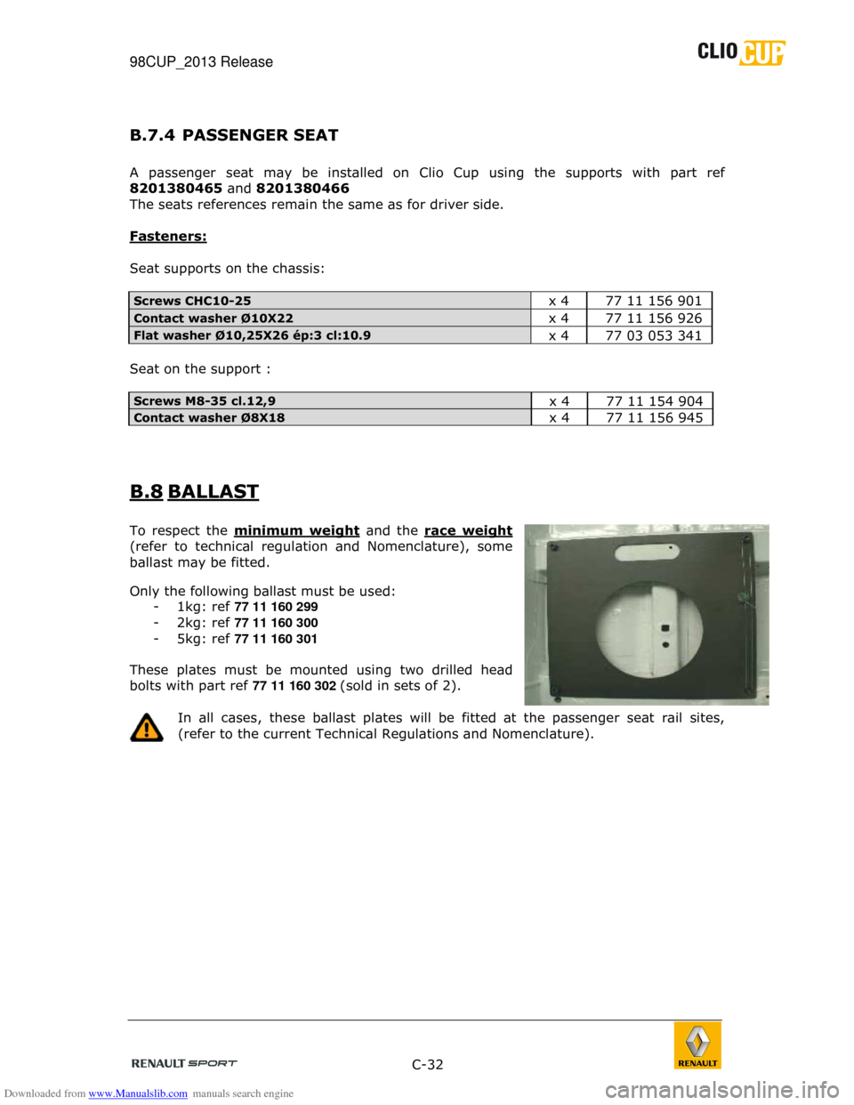
To respect the minimum weight
and the race weight
(refer to technical regulation and Nomenclature), s ome
ballast may be fitted.
Only the following ballast must be used: - 1kg: ref 77 11 160 299
- 2kg: ref 77 11 160 300
- 5kg: ref 77 11 160 301
These plates must be mounted using two drilled head
bolts with part ref 77 11 160 302 (sold in sets of 2).
In all cases, these ballast plates will be fitted a t the passenger seat rail sites,
(refer to the current Technical Regulations and Nom enclature).