2013 Ram 1500 key
[x] Cancel search: keyPage 101 of 196

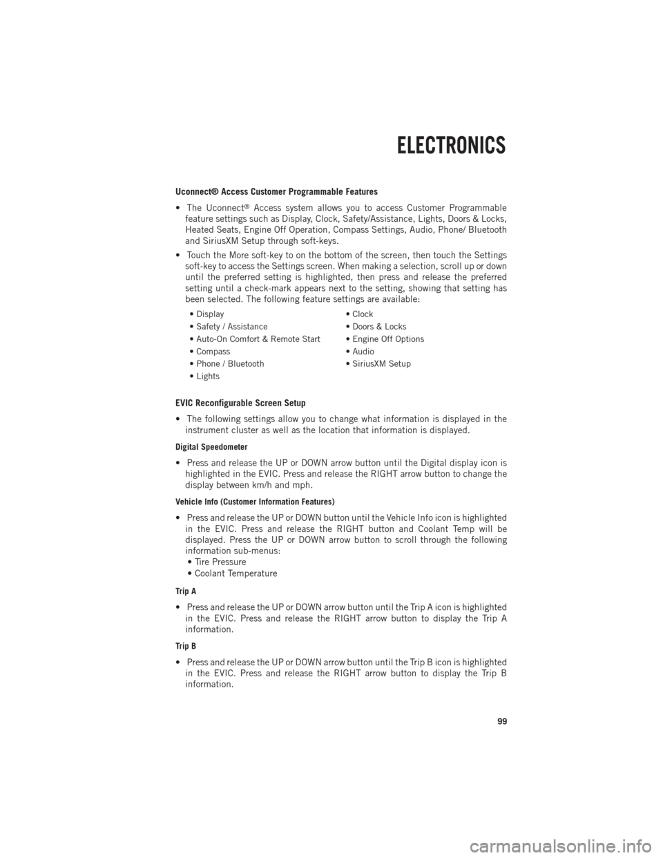
Uconnect® Access Customer Programmable Features
• The Uconnect
®Access system allows you to access Customer Programmable
feature settings such as Display, Clock, Safety/Assistance, Lights, Doors & Locks,
Heated Seats, Engine Off Operation, Compass Settings, Audio, Phone/ Bluetooth
and SiriusXM Setup through soft-keys.
• Touch the More soft-key to on the bottom of the screen, then touch the Settings soft-key to access the Settings screen. When making a selection, scroll up or down
until the preferred setting is highlighted, then press and release the preferred
setting until a check-mark appears next to the setting, showing that setting has
been selected. The following feature settings are available:
• Display • Clock
• Safety / Assistance • Doors & Locks
• Auto-On Comfort & Remote Start • Engine Off Options
• Compass • Audio
• Phone / Bluetooth • SiriusXM Setup
• Lights
EVIC Reconfigurable Screen Setup
• The following settings allow you to change what information is displayed in the instrument cluster as well as the location that information is displayed.
Digital Speedometer
• Press and release the UP or DOWN arrow button until the Digital display icon ishighlighted in the EVIC. Press and release the RIGHT arrow button to change the
display between km/h and mph.
Vehicle Info (Customer Information Features)
• Press and release the UP or DOWN button until the Vehicle Info icon is highlightedin the EVIC. Press and release the RIGHT button and Coolant Temp will be
displayed. Press the UP or DOWN arrow button to scroll through the following
information sub-menus:• Tire Pressure
• Coolant Temperature
Trip A
• Press and release the UP or DOWN arrow button until the Trip A icon is highlighted in the EVIC. Press and release the RIGHT arrow button to display the Trip A
information.
Trip B
• Press and release the UP or DOWN arrow button until the Trip B icon is highlightedin the EVIC. Press and release the RIGHT arrow button to display the Trip B
information.
ELECTRONICS
99
Page 106 of 196

POWER OUTLETS
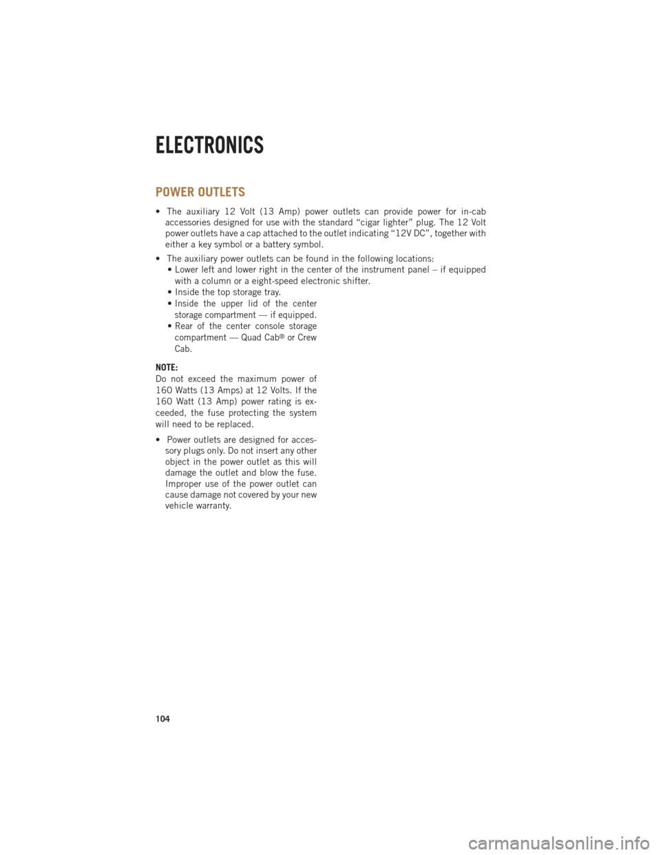
• The auxiliary 12 Volt (13 Amp) power outlets can provide power for in-cabaccessories designed for use with the standard “cigar lighter” plug. The 12 Volt
power outlets have a cap attached to the outlet indicating “12V DC”, together with
either a key symbol or a battery symbol.
• The auxiliary power outlets can be found in the following locations: • Lower left and lower right in the center of the instrument panel – if equipped
with a column or a eight-speed electronic shifter.
• Inside the top storage tray.
•
Inside the upper lid of the center
storage compartment — if equipped.
•Rear of the center console storage
compartment — Quad Cab®or Crew
Cab.
NOTE:
Do not exceed the maximum power of
160 Watts (13 Amps) at 12 Volts. If the
160 Watt (13 Amp) power rating is ex-
ceeded, the fuse protecting the system
will need to be replaced.
• Power outlets are designed for acces- sory plugs only. Do not insert any other
object in the power outlet as this will
damage the outlet and blow the fuse.
Improper use of the power outlet can
cause damage not covered by your new
vehicle warranty.
ELECTRONICS
104
Page 110 of 196

TONNEAU COVER
• The Tonneau Cover can be removed and reinstalled by using the locking clampslocated underneath the Tonneau Cover.
NOTE:
Be sure that the Tonneau Cover is secured before driving.
EASY-OFF TAILGATE
•To simplify mounting of a camper unit with an overhang, the tailgate can be removed.
NOTE:
If your vehicle is equipped with a rear camera or RKE the electrical connector must
be disconnected prior to removing the tailgate.
Removing the Tailgate
• Disconnect the wiring harness for the rear camera or RKE (if equipped).
• Unlatch the tailgate and remove the support cables by releasing the lock tang from the pivot.
• Raise the right side of the tailgate until the right side pivot clears the hanger bracket.
• Slide the entire tailgate to the right to free the left side pivot.
• Remove the tailgate from the vehicle.
NOTE:
Do not carry the tailgate loose in the truck pickup box.
Locking Tailgate
• The lock is located next to the tailgate handle. The tailgate can be locked using the vehicle key.
WARNING!
To avoid inhaling carbon monoxide, which is deadly, the exhaust system on vehicles
equipped with “Cap or Slide-In Campers” should extend beyond the overhanging
camper compartment and be free of leaks.
UTILITY
108
Page 113 of 196

•Storage bins feature two removable drain plugs (to allow water to drain from bins).
To remove plug, pull up on the edge. To install, push plug downward into drain hole.
• The RamBox®storage bins can be locked and unlocked using the vehicle key or
the remote keyless entry transmitter.
NOTE:
Provisions are provided in the bins for cargo dividers and shelf supports. These
accessories (in addition to other RamBox
®accessories) are available from MOPAR®.
RamBox® Storage Bin Cover Emergency Release Lever
• As a security measure, a Storage Bin Cover Emergency Release is built into the storage bin cover latching mechanism.
NOTE:
In the event of an individual being locked inside the storage bin, the storage bin cover
can be opened from inside of the bin by pulling on the glow-in-the-dark lever
attached to the storage bin cover latching mechanism.
Bed Extender
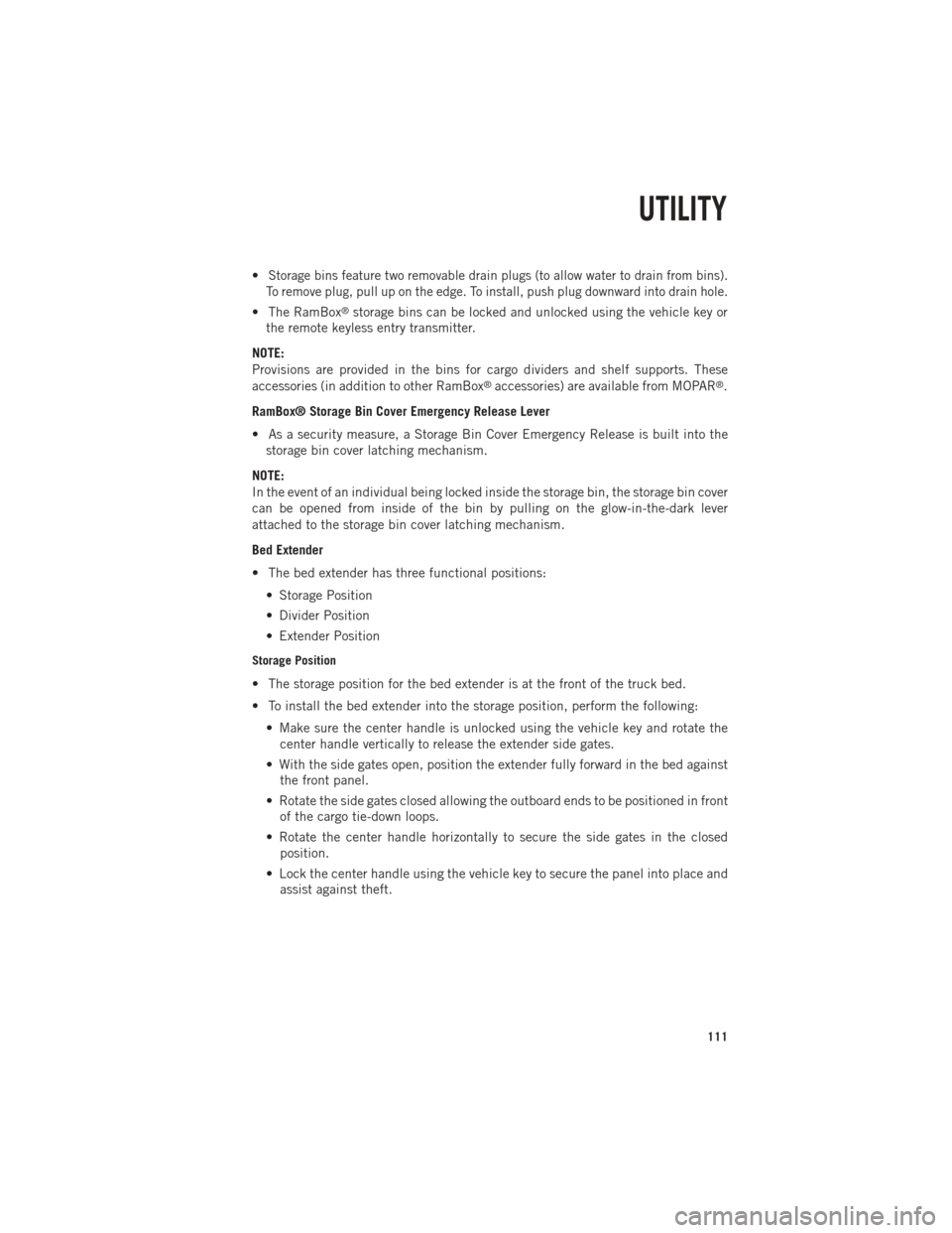
• The bed extender has three functional positions: • Storage Position
• Divider Position
• Extender Position
Storage Position
• The storage position for the bed extender is at the front of the truck bed.
• To install the bed extender into the storage position, perform the following:• Make sure the center handle is unlocked using the vehicle key and rotate thecenter handle vertically to release the extender side gates.
• With the side gates open, position the extender fully forward in the bed against the front panel.
• Rotate the side gates closed allowing the outboard ends to be positioned in front of the cargo tie-down loops.
• Rotate the center handle horizontally to secure the side gates in the closed position.
• Lock the center handle using the vehicle key to secure the panel into place and assist against theft.
UTILITY
111
Page 114 of 196

Divider Position
• There are 11 divider slots along the bed inner panels which allow for variouspositions to assist in managing your cargo.
• To install the bed extender into a divider position perform the following: • Make sure the center handle is unlocked using the vehicle key and rotate thecenter handle vertically to release the extender side gates.
• With the side gates open, position the extender so the outboard ends align with the intended slots in the sides of the bed.
• Rotate the side gates closed so that the outboard ends are secured into the intended slots of the bed.
• Rotate the center handle horizontally to secure the side gates in the closed position.
• Lock the center handle to secure the panel into place and assist against theft.
Extender Position
• The bed extender will add an additional 15 in (38 cm) in the back of the truck when additional cargo room is needed.
• To install the bed extender into the extender position, perform the following: • Lower the tailgate.
• Make sure the center handle is unlocked and rotate the center handle verticallyin order to release the extender side gates.
• Fit the end of the side gate ends onto the pin and handle.
• Rotate the handles to the horizontal position to secure into place.
Bed Rail Tie-Down System
• There are two adjustable cleats on each side of the bed that can be used to assist in securing cargo.
• Each cleat must be located and tightened down in one of the detents, along either rail, in order to keep cargo properly secure.
• To move the cleat to any position on the rail, turn the nut counterclockwise, approximately three turns. Then, pull out on the cleat and slide it to the detent
nearest the desired location. Make sure the cleat is seated in the detent and
tighten the nut.
• To remove the cleats from the utility rail, remove the end cap by pushing up on the locking tab, located on the bottom of the end cap. Slide the cleat off the end of the
rail.
UTILITY
112
Page 120 of 196

RECREATIONAL TOWING (BEHIND MOTORHOME, ETC.)
Towing This Vehicle Behind Another Vehicle
Towing ConditionWheels OFF The
Ground Two-Wheel Drive
Models Four-Wheel Drive Mod-
els
Flat Tow NONE NOT ALLOWED See Instructions:
• Automatic trans-
mission in PARK
• Manual transmis-
sion in gear (NOT
in NEUTRAL)
• Transfer case in
NEUTRAL (N)
• Tow in forward
direction
Dolly Tow Front NOT ALLOWED NOT ALLOWED
Rear OK NOT ALLOWED
On Trailer ALL OK OK
Recreational Towing – Two-Wheel Drive Models
• DO NOT flat tow this vehicle. Damage to the drivetrain will result.
• Recreational towing (for two-wheel drive models) is allowed ONLY if the rear wheels are OFF the ground. This may be accomplished using a tow dolly or vehicle
trailer. If using a tow dolly, follow this procedure:• Properly secure the dolly to the tow vehicle, following the dolly manufacturer's
instructions.
• Drive the rear wheels onto the tow dolly.
• Firmly set the parking brake. Place automatic transmission in PARK, manual transmission in gear (not in Neutral).
• Properly secure the rear wheels to the dolly, following the dolly manufacturer's instructions.
• Remove the key fob from the ignition switch.
• Install a suitable clamping device, designed for towing, to secure the front wheels in the straight position.
UTILITY
118
Page 129 of 196

COOL-DOWN IDLE CHART
TURBO "COOL DOWN" CHART
Driving Conditions Load Turbo TempIdle Time
(in minutes)
Before Shut Down
Stop and Go EmptyCoolLess than 1
Stop and Go MediumWarm 1
Highway Speeds Medium Warm2
City Traffic Max. GCWR Warm3
Highway Speeds Max. GCWR Warm4
Uphill Grade Max. GCWR Hot5
DIESEL EXHAUST FLUID
• Diesel Exhaust Fluid (DEF) sometimes known simply by the name of its active
component, UREA—is a key component of selective catalytic reduction (SCR)
systems, which help diesel vehicles meet stringent emission regulations. DEF is a
liquid reducing agent that reacts with engine exhaust in the presence of a catalyst
to convert smog-forming nitrogen oxides (NOx) into harmless nitrogen and water
vapor.
• Your vehicle is equipped with a Selective Catalytic Reduction system in order to meet the very stringent diesel emissions standards required by the Environmental
Protection Agency. Selective Catalytic Reduction (SCR) is the first and only
technology in decades to be as good for the environment as it is good for business
and vehicle performance.
• The purpose of the SCR system is to reduce levels of NOx (oxides of nitrogen emitted from engines) that are harmful to our health and the environment to an
almost near-zero level. Small quantities of Diesel Exhaust Fluid (DEF) are injected
into the exhaust upstream of a catalyst where, when vaporized, convert smog-
forming nitrogen oxides (NOx) into harmless nitrogen (N2) and water vapor (H2O),
two natural components of the air we breathe. You can operate with the comfort
that your vehicle is contributing to a cleaner, healthier world environment for this
and generations to come.
DIESEL
127
Page 152 of 196

EMERGENCY TOW HOOKS
• If your vehicle is equipped with tow hooks, they are mounted in the front.
• For off-road recovery, it is recommended to use both of the front tow hooks tominimize the risk of damage to the vehicle.
CAUTION!
Tow hooks are for emergency use only, to rescue a vehicle stranded off-road. Do not
use tow hooks for tow truck hookup or highway towing. You could damage your
vehicle. Tow straps are recommended when towing the vehicle; chains may cause
vehicle damage.
WARNING!
• Chains are not recommended for freeing a stuck vehicle. Chains may break,
causing serious injury or death.
• Stand clear of vehicles when pulling with tow hooks. Tow straps and chains may
break, causing serious injury.
SHIFT LEVER OVERRIDE
• If a malfunction occurs and the shift lever cannot be moved out of the PARKposition, you can use the following procedure to temporarily move the shift lever.
• Have your vehicle inspected by your local authorized dealer immediately if the shift lever override has been used.
Column Shifter
•
Tilt the steering wheel to the full up
position and firmly set the parking brake.
•Turn the Key Fob to the ACC or ON/RUN
position without starting the engine.
•Press and maintain firm pressure on the
brake pedal.
• Using a screwdriver, press and hold the override tab through the access
port (ringed circle) on the bottom of
the steering column.
• Move the shift lever into the NEUTRAL position and start the vehicle.
• Release the parking brake.
WHAT TO DO IN EMERGENCIES
150