2013 PEUGEOT 5008 brake
[x] Cancel search: brakePage 183 of 364
PRACTICAL INFORMATION
181
TEMPORARY PUNCTURE REPAIR KIT
Complete system consisting of a com-
pressor and a sealant cartridge which
permits temporary repair
of a tyre so
that you can drive to the nearest ga-
rage.
It is designed to repair most punctures
which could affect the tyre, located on
the tyre tread or shoulder.
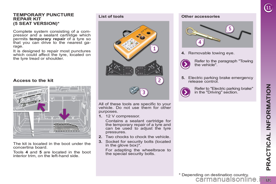
All of these tools are specifi c to your
vehicle. Do not use them for other
purposes.
1.
12 V compressor.
Contains a sealant cartridge for
the temporary repair of a tyre and
can be used to adjust the tyre
pressures.
2.
Two chocks to chock the vehicle.
3.
Socket for security bolts (located
in the glove box) * .
For adapting the wheelbrace to
the special security bolts.
List of tools
Other accessories
4.
Removable towing eye.
Refer to "Electric parking brake"
in the "Driving" section.
Refer to the paragraph "Towing
the vehicle".
5.
Electric parking brake emergency
release control.
Access to the kit
(5 SEAT VERSION)
*
The kit is located in the boot under the
concertina board.
Tools 4
and 5
are located in the boot
interior trim, on the left-hand side.
*
Depending on destination country.
Page 193 of 364
PRACTICAL INFORMATION
191
Other accessories
Wheel with trim
When removing the wheel
,
detach the trim fi rst using the
wheelbrace 1
pulling at the valve
passage hole.
When refi tting the wheel
, refi t the
trim starting by placing its notch fac-
ing the valve and press around its
edge with the palm of your hand.
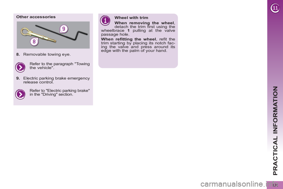
8.
Removable towing eye.
Refer to "Electric parking brake"
in the "Driving" section.
Refer to the paragraph "Towing
the vehicle".
9.
Electric parking brake emergency
release control.
Page 196 of 364
PRACTICAL INFORMATION
194
Parking the vehicle
Immobilise the vehicle where
it does not block traffi c: the
ground must be level, stable and
non-slippery ground.
Apply the parking brake unless it
has been programmed to automatic
mode, switch off the ignition and en-
gage fi rst gear * to lock the wheels.
Check that the braking warning lamp
and the P
warning lamp on the park-
ing brake control come on.
If necessary, place a chock under the
wheel diagonally opposite the wheel
to be changed.
The occupants must get out of the ve-
hicle and wait where they are safe.
Never go underneath a vehicle raised
using a jack; use an axle stand.
Removing a wheel
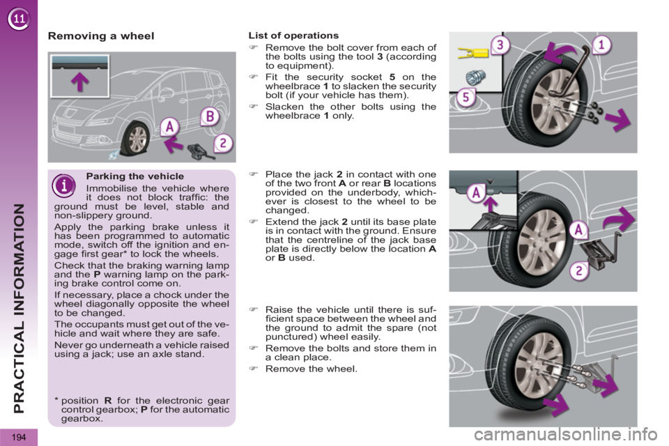
List of operations
�)
Remove the bolt cover from each of
the bolts using the tool 3
(according
to equipment).
�)
Fit the security socket 5
on the
wheelbrace 1
to slacken the security
bolt (if your vehicle has them).
�)
Slacken the other bolts using the
wheelbrace 1
only.
�)
Place the jack 2
in contact with one
of the two front A
or rear B
locations
provided on the underbody, which-
ever is closest to the wheel to be
changed.
�)
Extend the jack 2
until its base plate
is in contact with the ground. Ensure
that the centreline of the jack base
plate is directly below the location A
or B
used.
�)
Raise the vehicle until there is suf-
fi cient space between the wheel and
the ground to admit the spare (not
punctured) wheel easily.
�)
Remove the bolts and store them in
a clean place.
�)
Remove the wheel.
*
position R
for the electronic gear
control gearbox; P
for the automatic
gearbox.
Page 201 of 364
PRACTICAL INFORMATION
Rear lamps
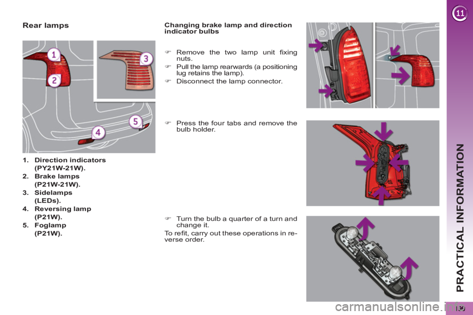
1.
Direction indicators
(PY21W-21W).
2.
Brake lamps
(P21W-21W).
3.
Sidelamps
(LEDs).
4.
Reversing lamp
(P21W).
5.
Foglamp
(P21W).
Changing brake lamp and direction
indicator bulbs
�)
Press the four tabs and remove the
bulb holder.
�)
Remove the two lamp unit fi xing
nuts.
�)
Pull the lamp rearwards (a positioning
lug retains the lamp).
�)
Disconnect the lamp connector.
�)
Turn the bulb a quarter of a turn and
change it.
To r efi t, carry out these operations in re-
verse order.
Page 202 of 364
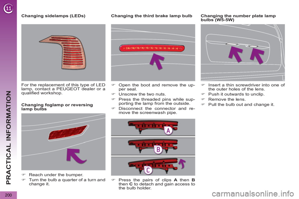
PRACTICAL INFORMATION
200
Changing the third brake lamp bulb
Changing foglamp or reversing
lamp bulbs
�)
Reach under the bumper.
�)
Turn the bulb a quarter of a turn and
change it.
�)
Open the boot and remove the up-
per seal.
�)
Unscrew the two nuts.
�)
Press the threaded pins while sup-
porting the lamp from the outside.
�)
Disconnect the connector and re-
move the screenwash pipe.
�)
Press the pairs of clips A
then B
then C
to detach and gain access to
the bulb holder.
Changing sidelamps (LEDs)
For the replacement of this type of LED
lamp, contact a PEUGEOT dealer or a
qualifi ed workshop.
�)
Insert a thin screwdriver into one of
the outer holes of the lens.
�)
Push it outwards to unclip.
�)
Remove the lens.
�)
Pull the bulb out and change it.
Changing the number plate lamp
bulbs (W5-5W)
Page 207 of 364
PRACTICAL INFORMATION
205
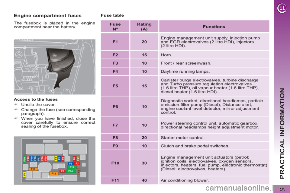
Engine compartment fuses
The fusebox is placed in the engine
compartment near the battery.
Access to the fuses
�)
Unclip the cover.
�)
Change the fuse (see corresponding
paragraph).
�)
When you have fi nished, close the
cover carefully to ensure correct
sealing of the fusebox.
Fuse table
Fuse
N°
Rating
(A)
Functions
F1
20
Engine management unit supply, injection pump
and EGR electrovalves (2 litre HDI), injectors
(2 litre HDI).
F2
15
Horn.
F3
10
Front / rear screenwash.
F4
10
Daytime running lamps.
F5
15
Canister purge electrovalves, turbine discharge
and Turbo pressure regulation electrovalves
(1.6 litre THP), oil vapour heater (1.6 litre THP),
diesel heater (1.6 litre HDI).
F6
10
Diagnostic socket, directional headlamps, particle
emission fi lter pump (Diesel), Distance alert,
engine coolant level detector, mirror adjustment
control.
F7
10
Power steering control unit, automatic gearbox,
directional headlamps height adjustment motor.
F8
20
Starter motor control.
F9
10
Clutch and brake pedal switches.
F10
30
Engine management unit actuators (petrol:
ignition coils, electrovalves, oxygen sensors,
injectors, heaters, fuel pump, electronic thermostat)
(Diesel: electrovalves, heaters).
F11
40
Air conditioning blower.
Page 209 of 364
PRACTICAL INFORMATION
207
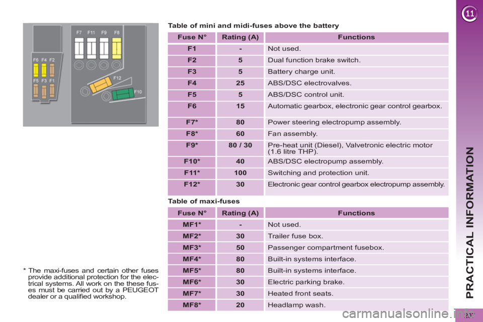
Table of mini and midi-fuses above the battery
Fuse N°
Rating
(A)
Functions
F1
-
Not used.
F2
5
Dual function brake switch.
F3
5
Battery charge unit.
F4
25
ABS/DSC electrovalves.
F5
5
ABS/DSC control unit.
F6
15
Automatic gearbox, electronic gear control gearbox.
F7 *
80
Power steering electropump assembly.
F8
*
60
Fan assembly.
F9 *
80 / 30
Pre-heat unit (Diesel), Valvetronic electric motor
(1.6 litre THP).
F10 *
40
ABS/DSC electropump assembly.
F11 *
100
Switching and protection unit.
F12 *
30
Electronic gear control gearbox electropump assembly.
Fuse N°
Rating (A)
Functions
MF1 *
-
Not used.
MF2 *
30
Trailer fuse box.
MF3 *
50
Passenger compartment fusebox.
MF4 *
80
Built-in systems interface.
MF5 *
80
Built-in systems interface.
MF6 *
30
Electric parking brake.
MF7 *
30
Heated front seats.
MF8 *
20
Headlamp wash.
Table of maxi-fuses
*
The maxi-fuses and certain other fuses
provide additional protection for the elec-
trical systems. All work on the these fus-
es must be carried out by a PEUGEOT
dealer or a qualifi ed workshop.
Page 215 of 364

PRACTICAL INFORMATION
213
TOWING A TRAILER
Your vehicle is primarily designed for
transporting people and luggage, but it
may also be used for towing a trailer.
Driving advice
Side wind
�)
Take into account the increased
sensitivity to side wind.
Cooling
Towing a trailer on a slope increases
the temperature of the coolant.
As the fan is electrically controlled, its
cooling capacity is not dependent on
the engine speed.
�)
To lower the engine speed, reduce
your speed.
Towbar suitable for the attachment of a
trailer or installation of a bicycle carrier,
with additional lighting and signalling.
Distribution of loads
�)
Distribute the load in the trailer so
that the heaviest items are as close
as possible to the axle and the nose
weight approaches the maximum
permitted without exceeding it.
Air density decreases with altitude, thus
reducing engine performance. Above
1 000 metres, the maximum towed load
must be reduced by 10 % for every
1 000 metres of altitude.
Driving with a trailer places greater de-
mands on the towing vehicle and the
driver must take particular care.
We recommend the use of
genuine PEUGEOT towbars
and their harnesses that have
been tested and approved from the
design stage of your vehicle, and that
the fi tting of the towbar is entrusted
to a PEUGEOT dealer or a qualifi ed
workshop.
If the towbar is not fi tted by a
PEUGEOT dealer, it is imperative
that it is fi tted in accordance with the
vehicle manufacturer's instructions.
General
recommendations
Observe the legislation in force in
your country.
Ensure that the weight of the tow-
ing vehicle is higher than that of the
towed vehicle.
The person at the wheel of the towed
vehicle must have a valid driving li-
cence.
When towing a vehicle with all four
wheels on the ground, always use an
approved towing bar; rope and straps
are prohibited.
When towing a vehicle with the en-
gine off, there is no longer any power
assistance for braking or steering.
In the following cases, you must al-
ways call on a professional recovery
service:
- vehicle broken down on a motor-
way or fast road,
- 4 wheel drive vehicle,
- when it is not possible to put the
gearbox into neutral, unlock the
steering, or release the parking
brake,
- towing with only two wheels on
the ground,
- where there is no approved towing
bar available...
Refer to the "Technical data" section for
details of the weights and towed loads
which apply to your vehicle.