Page 84 of 402
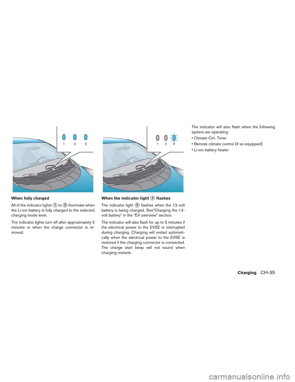
When fully charged
All of the indicator lights
�1to�3illuminate when
the Li-ion battery is fully charged to the selected
charging mode level.
The indicator lights turn off after approximately 5
minutes or when the charge connector is re-
moved. When the indicator light
�3flashes
The indicator light
�3flashes when the 12-volt
battery is being charged. See�Charging the 12-
volt battery� in the�EV overview� section.
The indicator will also flash for up to 5 minutes if
the electrical power to the EVSE is interrupted
during charging. Charging will restart automati-
cally when the electrical power to the EVSE is
restored if the charging connector is connected.
The charge start beep will not sound when
charging restarts. The indicator will also flash when the following
system are operating:
Climate Ctrl. Timer
Remote climate control (if so equipped)
Li-ion battery heater
ChargingCH-35
Page 143 of 402
1. Side ventilator
2. Meters and gauges
3. Center multi-function control panel (SeeLEAF Navigation System Owner’s Manual.)
— Navigation system
— Vehicle information and setting buttons
— Bluetooth® Hands-Free Phone System — Audio system
4. Hazard warning flasher switch
5. Center ventilator
6. Rear window defroster switch
7. Front passenger supplemental air bag
8. Hood release handle
9. Power switch 10. iPod® connector/USB connector (See
LEAF Navigation System Owner’s Manual.)
11. Power outlet
12. Auxiliary input jack (See LEAF Navigation System Owner’s Manual.)
13. Front passenger air bag status light/ Approaching Vehicle Sound for Pedestri-
ans (VSP) system warning light
14. Heater and air conditioner control
15. Glove box
INSTRUMENT PANEL
2-4Instruments and controls
Page 147 of 402
 .
The power meter also indicates if the power
provided to the motor is limited or if regenerative
braking is limited. When power or regenerative")
the regenerative brake system (Li-ion battery
charging) .
The power meter also indicates if the power
provided to the motor is limited or if regenerative
braking is limited. When power or regenerative
braking is limited, the circles on the display
change from a double circle to a single circle
�2.
Regenerative braking is automatically reduced
when the Li-ion battery is fully charged to prevent
the Li-ion battery from becoming overcharged.
Regenerative braking is also automatically re-
duced when the Li-ion battery temperature is
high/low (indicated by the red/blue zones on the
Li-ion battery temperature gauge) to prevent Li-
ion battery damage.
The more regenerative braking is reduced the
more double circles change to single circles
If the Li-ion battery charge is low, power provided
to the traction motor is reduced. Motor output is
also limited if the Li-ion battery temperature is
high/low (indicated by the red/blue zones on the
Li-ion battery temperature gauge) or the Li-ion
battery charge level is low.
The more power provided to the traction motor is
reduced the more double circles change to
single circles.
DRIVING RANGE
The driving range�1(miles or km) provides an
estimated distance that the vehicle can be driven
before recharging is necessary. The driving range
is constantly being calculated, based on the
amount of available Li-ion battery charge and the
actual power consumption average.
NOTE:
The driving range display will flash when
the low battery charge warning light illu-
minates. Additionally, if you continue to
drive the vehicle in this state and the Li-
ion battery is close to being completely
discharged, “---” will be displayed. Charge
the Li-ion battery as soon as possible.
When the Li-ion battery is charged, the
original display will be restored.
After the vehicle is charged, the displayed
driving range is calculated based on the
actual average energy consumption of the
previous driving. The displayed driving
range will vary every time the vehicle is
fully charged.
The driving range will increases or de-
creases when the air conditioner, heater
or Li-ion battery warmer is turned on or
off, or the vehicle is shifted between D
(Drive) and ECO, or when any other acces-
sory is turned on or off based on driving.
2-8Instruments and controls
Page 149 of 402
LI-ION BATTERY CAPACITY LEVEL
GAUGE
This gauge indicates the amount of charge the
Li-ion battery is capable of storing.
When the capacity of the Li-ion battery de-
creases with age and usage, the level of the
gauge will also decrease.
OUTSIDE AIR TEMPERATURE
The outside air temperature is displayed in °F or
°C.
The display may differ from the actual outside
temperature displayed on various signs or bill-
boards.
ECO INDICATOR
The ECO indicator displays how economically
the vehicle is being operated.
The meter display is affected by the following
conditions:
Accelerator pedal operation.
Brake pedal operation.
Driving conditions.
Traffic conditions.
Heater and air conditioner usage.
2-10Instruments and controls
Page 184 of 402

To turn the fog lights on, turn the headlight switch
to the
position, then turn the switch to the
position. To turn them off, turn the switch to
the OFF position.
The headlights must be on for the fog lights to
operate. The heated steering wheel system is designed to
operate only when the surface temperature of the
steering wheel is below approximately 68°F
(20°C) .
Push the heated steering wheel switch to warm
the steering wheel when the power switch is in
the ON position. The indicator light
�1on the
switch will illuminate.
If the surface temperature of the steering wheel is
below approximately 68°F (20°C) , the system will
heat the steering wheel and cycle off and on to
maintain a temperature above 68°F (20°C) . The indicator light will remain on as long as the sys-
tem is on.
Push the switch again to turn the heated steering
wheel system off manually. The indicator light turn
off.
NOTE:
If the surface temperature of the steering
wheel is above 68°F (20°C) when the
switch is turned on, the system will not
heat the steering wheel. This is not a mal-
function.
If the outside temperature is low (approxi-
mately 50°F (10°C) or less) and the Climate
Ctrl. Timer or Remote Climate Control are
used, the steering wheel heater will auto-
matically operate in the following condi-
tions. – When using the Climate Ctrl. Timer: Operates from approximately 15 min-
utes before the set departure time until
the set departure time.
– When using Remote Climate Control: Operates 15 minutes after Remote Cli-
mate Control starts.
FOG LIGHT SWITCH (IF SO
EQUIPPED) HEATED STEERING WHEEL SWITCH
Instruments and controls2-45
Page 185 of 402
The heated steering wheel consumes less
power than the heater and can be used to
either help extend vehicle range by reduc-
ing heater use or to maximize comfort by
supplementing the heater.
To sound the horn, push the center pad area of
the steering wheel.
WARNING
Do not disassemble the horn. Doing so
could affect proper operation of the
supplemental front air bag system. Tam-
pering with the supplemental front air
bag system may result in serious per-
sonal injury. To activate the ECO mode, press the ECO
switch
�1on the right side of the steering wheel.
The “ECO indicator light” on the instrument clus-
ter will illuminate.
To deactivate the ECO mode, press the ECO
switch
�1again. The “ECO indicator light” on the
instrument cluster will go out.
See “Electronic Shift Control System” in the
“Starting and Driving” section.
HORN ECO SWITCH
2-46Instruments and controls
Page 186 of 402

WARNING
Do not use or allow occupants to use the
seat heater if you or the occupants can-
not monitor elevated seat temperatures
or have an inability to feel pain in those
body parts in contact with the seat. Use
of the seat heater by such people could
result in serious injury.CAUTION
Do not use the seat heater for ex- tended periods or when no one is us-
ing the seat.
Do not put anything on the seat which insulates heat, such as a blanket,
cushion, seat cover, etc. Otherwise,
the seat may become overheated.
Do not place anything hard or heavy on the seat or pierce it with a pin or simi-
lar object. This may result in damage
to the heater.
Any liquid spilled on the heated seat should be removed immediately with a
dry cloth.
When cleaning the seat, never use gasoline, thinner, or any similar mate-
rials.
If any abnormalities are found or the heated seat does not operate, turn the
switch off and have the system
checked by a NISSAN certified LEAF
dealer.
Front
Rear
HEATED SEAT SWITCH
Instruments and controls2-47
Page 187 of 402

The front seats and the rear outboard seats can
be warmed by built-in heaters. The switches lo-
cated on the center console and at the side of the
front passenger seatback can be operated inde-
pendently of each other.
1. Place the power switch in the ON position.
2. Push the LO or HI position of the switch, asdesired, depending on the temperature. The
indicator light in the switch will illuminate.
3. To turn off the heater, return the switch to the level position. Make sure the indicator light
goes off.
The heater is controlled by a thermostat, auto-
matically turning the heater on and off. The indi-
cator light will remain on as long as the switch is
on.
When the vehicle’s interior is warmed, or before
you leave the vehicle, be sure to turn the switch
off.
NOTE:
The heated seats consumes less power
than the heater and can be used to either
help extend vehicle range by reducing
heater use or to maximize comfort by
supplementing the heater. The vehicle should be driven with the Vehicle
Dynamic Control (VDC) system on for most driv-
ing conditions.
If the vehicle is stuck in mud or snow, the VDC
system reduces the traction motor output to re-
duce wheel spin. The traction motor speed will be
reduced even if the accelerator is depressed to
the floor. If maximum traction motor power is
needed to free a stuck vehicle, turn the VDC
system off.
To turn off the VDC system, push the VDC OFF
switch. The
indicator will illuminate.Push the VDC OFF switch again to turn on the
VDC system, or the VDC is automatically turned
back on when the power switch is placed in the
off position and then placed back in the READY
to drive position. See
�Vehicle Dynamic Control
(VDC) system� in the�5 Starting and driving�
section.
VEHICLE DYNAMIC CONTROL (VDC)
OFF SWITCH
2-48Instruments and controls

— Navigation system
— Vehicle information and setting buttons
— Bluet")

