Page 9 of 39

NOTE:
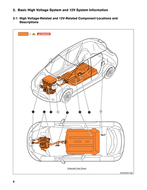
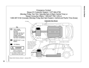
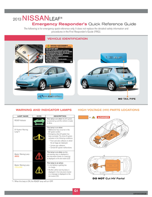
Components with white number in black background are high voltage components.No. Component
LocationDescription
a Charge
port Under hood Connecting port for EVSE (Electric Vehicle
Supply Equipment) . Two ports are available:
Normal charge and quick charge (if so
equipped) .
b High voltage
cables Under hood and
undercarriage Orange-colored power cables carry high volt-
age current between each of the high voltage
components.
c Traction Motor Under hood Converts three-phase AC power to drive
power (torque) which propels the vehicle.
Inverter Under hood Converts the DC power stored in the Li-ion
battery to three-phase AC power and controls
motor torque (revolution) by regulating the
motor current.
Electric air condi-
tioner compressor Under hood
Air conditioner compressor
Power Distribution
Module (PDM)
• On Board Charger
• DC/DC Converter
• High voltage junction box (J/B) Under hood
The PDM includes an On Board Charger, DC/DC
converter and high voltage junction box (J/B) .
The On Board Charger converts single-phase AC
power from a home power outlet to DC power and
increases the voltage in order to charge the Li-ion
battery.
The DC/DC converter reduces the voltage of the Li-ion
battery to provide power to the 12V battery in order to
operate the vehicle’s electric components (headlights,
audio system, etc.) .
The J/B provides electric power from the Li-ion battery
to all high voltage parts of the vehicle.
d 12V Battery Under hood A lead-acid battery that supplies power to the low
voltage devices.
e Cabin heater Interior (This unit is
installed behind the
instrument panel) This is the electric heat source for the cabin
heater. It heats the interior of the vehicle.
f Li-ion (Lithium ion)
battery Undercarriage Stores and outputs DC power (Maximum voltage
398.4V) needed to propel the vehicle.
g High voltage battery
service disconnect Rear seat floor Isolates the battery from the rest of the high volt-
age electrical system.
h Brake power supply
backup unit Cargo area (This unit
is installed behind a
trim panel to prevent
access) Power supply backup unit for the brake system. It
supplies power to the brake system if a malfunc-
tion occurs in the 12V battery.
9
Page 10 of 39
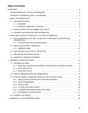
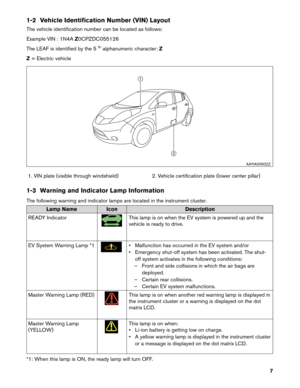
2-1.1 Li-ion Battery Pack Specifications
Li-ion battery voltage
360V nominal
(240V - 398.4V usable range)
Number of Li-ion battery modules in the pack 48
Li-ion battery dimensions 60.91 x 46.77 x 10.39 in. (1547 x 1188 x 264 mm)
Li-ion battery weight 606 lbs (275 kg)
2-2 High Voltage Safety Measures Circuit insulation
The high voltage positive (+) and negative (-) circuits are insulated
from
the metal chassis.
Reducing the risk of electrocution The high voltage components and harnesses have insulated cases or orange-colored coverings which provide insulation and easy
identification.
The high voltage battery case is electrically connected to the vehicle ground.
This connection helps protect the vehicle occupants and emergency
responders from high voltage electrical shock.
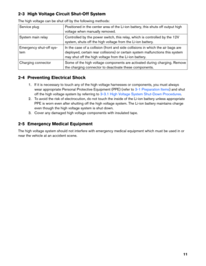
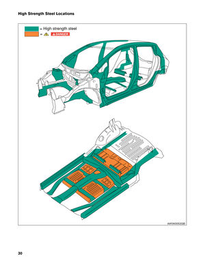
Identification The high voltage components are labeled “WARNING” similar to label
shown below. All high voltage harnesses are coated in orange.
2-2.1 Warning Label AAYIA0147ZZ
10
Page 11 of 39

2-3 High Voltage Circuit Shut-Off System
The
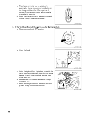
high voltage can be shut off by the following methods: Service plug
Positioned in the center area of the Li-ion battery, this shuts off output high
voltage
when manually removed.
System main relay Controlled by the power switch, this relay, which is controlled by the 12V system, shuts off the high voltage from the Li-ion battery.
Emergency shut-off sys-
tem In the case of a collision (front and side collisions in which the air bags are
deployed, certain rear collisions) or certain system malfunctions this system
may shut off the high voltage from the Li-ion battery.
Charging connector Some of the high voltage components are activated during charging. Remove the charging connector to deactivate these components.
2-4 Preventing Electrical Shock 1. If it is necessary to touch any of the high voltage harnesses or components, you must alwayswear appropriate Personal Protective Equipment (PPE) (refer to 3-1 Preparation Items) and shut
off
the high voltage system by referring to 3-3.1 High Voltage System Shut-Down Procedures.
2.
To avoid the risk of electrocution, do not touch the inside of the Li-ion battery unless appropriate
PPE is worn even after shutting off the high voltage system. The Li-ion battery maintains charge
even though the high voltage system is shut down.
3. Cover any damaged high voltage components with insulated tape.
2-5 Emergency Medical Equipment
The high voltage system should not interfere with emergency medical equipment which must be used in or
near the vehicle at an accident scene.
11
Page 12 of 39

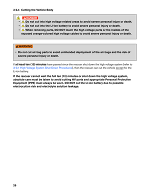
3. Emergency Response Steps
• Failure to properly shut down the high voltage electrical system before the
Emergency Response Procedures are performed will result in serious injury or death
from electrical shock. To prevent serious injury or death, DO NOT touch high voltage
harnesses or components without always wearing appropriate Personal Protective
Equipment (PPE) .
• If it is necessary to touch any of the high voltage harnesses or components you
must
always wear appropriate PPE to avoid electrical shock. Shut down the high
voltage system by following the steps outlined in 3-3.1 High Voltage System Shut-
Down
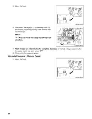
Procedures. Wait at least ten (10) minutes for complete discharge of the high
voltage
capacitor after the high voltage system has been shut down. • NEVER assume the LEAF is shut OFF simply because it is quiet.
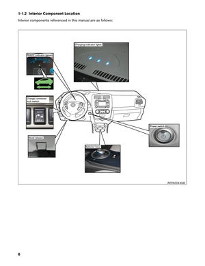
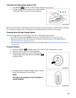
• If the READY indicator or charging indicator are ON, the high voltage system is
active.
• If possible, be sure to verify that the READY indicator on the instrument cluster
is
OFF and the high voltage system is stopped.
• Some of the under hood parts get hot and may cause serious burns. Use caution when working on or around these parts.
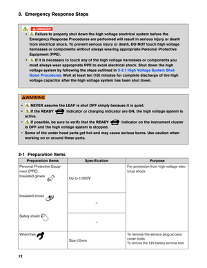
3-1 Preparation Items Preparation Items
Specification Purpose
Personal
Protective Equip-
ment (PPE):
Insulated gloves Up to 1,000V
For
protection from high voltage elec-
trical shock
Insulated shoes –
Safety
shield –
W
renches Size:10mm
T
o remove the service plug access
cover bolts.
To remove the 12V battery terminal bolt.
12
Page 13 of 39

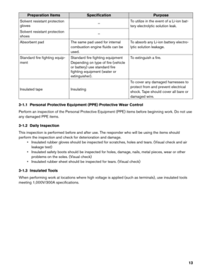
Preparation Items
Specification Purpose
Solvent resistant protection
gloves –
To utilize in the event of a Li-ion bat-
tery electrolytic solution leak.
Solvent resistant protection
shoes –
Absorbent pad The same pad used for internal
combustion engine fluids can be
used. To absorb any Li-ion battery electro-
lytic solution leakage.
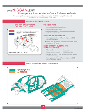
Standard fire fighting equip-
ment Standard fire fighting equipment
Depending on type of fire (vehicle
or battery) use standard fire
fighting equipment (water or
extinguisher) . To extinguish a fire.
Insulated tape Insulating To cover any damaged harnesses to
protect from and prevent electrical
shock. Tape should cover all bare or
damaged wire.
3-1.1 Personal Protective Equipment (PPE) Protective Wear Control
Perform an inspection of the Personal Protective Equipment (PPE) items before beginning work. Do not use
any damaged PPE items.
3-1.2 Daily Inspection
This inspection is performed before and after use. The responder who will be using the items should
perform the inspection and check for deterioration and damage. • Insulated rubber gloves should be inspected for scratches, holes and tears. (Visual check and airleakage test)
• Insulated safety boots should be inspected for holes, damage, nails, metal pieces, wear or other problems on the soles. (Visual check)
• Insulated rubber sheet should be inspected for tears. (Visual check)
3-1.3 Insulated Tools
When performing work at locations where high voltage is applied (such as terminals) , use insulated tools
meeting 1,000V/300A specifications.
13
Page 14 of 39
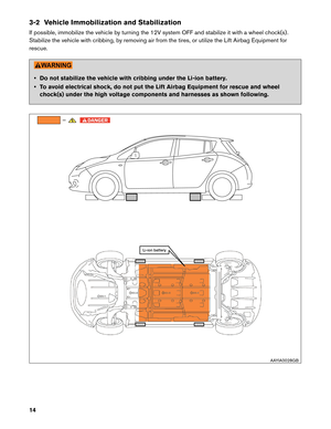
3-2 Vehicle Immobilization and Stabilization
If
possible, immobilize the vehicle by turning the 12V system OFF and stabilize it with a wheel chock(s) .
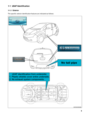
Stabilize the vehicle with cribbing, by removing air from the tires, or utilize the Lift Airbag Equipment for
rescue. • Do not stabilize the vehicle with cribbing under the Li-ion battery.
•
To avoid electrical shock, do not put the Lift Airbag Equipment for rescue and wheel
chock(s) under the high voltage components and harnesses as shown following. =
Li-ion battery
AAYIA0028GB
14
Page 15 of 39
 system has
been automatically shut off at the time of")
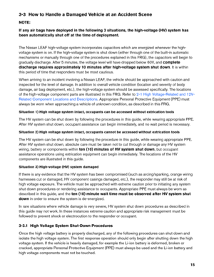
3-3 How to Handle a Damaged Vehicle at an Accident Scene
NO
TE:
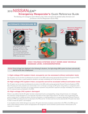
If any air bags have deployed in the following 3 situations, the high-voltage (HV) system has
been automatically shut off at the time of deployment.
The Nissan LEAF high-voltage system incorporates capacitors which are energized whenever the high-
voltage system is on. If the high-voltage system is shut down (either through one of the built-in automatic
mechanisms or manually through one of the procedures explained in this FRG) , the capacitors will begin to
gradually discharge. After 5 minutes, the voltage level will have dropped below 60V, and complete
discharge requires approximately 10 minutes after high-voltage system shut down. It is within
this period of time that responders must be most cautious.
When arriving to an incident involving a Nissan LEAF, the vehicle should be approached with caution and
inspected for the level of damage. In addition to overall vehicle condition (location and severity of body
damage, air bag deployment, etc.) , the high-voltage system should be assessed specifically. The locations
of the high-voltage component parts are illustrated in this FRG. Refer to 2-1 High Voltage-Related and 12V-
Related
Component Locations and Descriptions . Appropriate Personal Protective Equipment (PPE) must
always
be worn when approaching a vehicle of unknown condition, as described in this FRG.
Situation 1) High voltage system intact, occupants can be accessed without extrication tools
The HV system can be shut down by following the procedures in this guide, while wearing appropriate PPE.
After HV system shut down, occupant assistance can begin immediately, and no wait period is necessary.
Situation 2) High voltage system intact, occupants cannot be accessed without extrication tools
The HV system can be shut down by following the procedure in this guide, while wearing appropriate PPE.
After HV system shut down, absolute care must be taken not to cut through or damage any HV system
wiring, battery or components within ten (10) minutes of HV system shut down, but occupant
assistance operations using extrication equipment can begin immediately. The locations of the HV
components are illustrated in this guide.
Situation 3) High-voltage (HV) system damaged
If there is any evidence that the HV system has been compromised (such as arcing/sparking, orange wiring
harnesses cut or damaged, HV component casings damaged, etc.) , the responder may still be at risk of
high voltage exposure. The vehicle must be approached with extreme caution prior to initiating any system
shut down procedures or rendering assistance to occupants. Appropriate PPE must always be worn as
described in this guide, and the ten (10) minute wait time must be observed after HV system shut
down in order to ensure the system is de-energized.
In rare situations where vehicle damage is very severe, HV system shut down procedures as described in
this guide may not work. In these instances extreme caution and appropriate risk management must be
followed to prevent shock or electrocution to the responder or occupant.
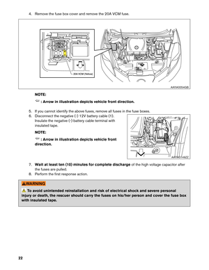
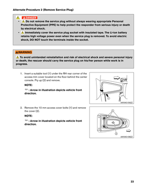
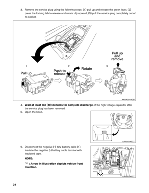
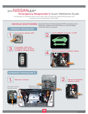
3-3.1 High Voltage System Shut-Down Procedures
Once the high voltage battery is properly discharged, any of the following procedures can shut down and
isolate the high voltage system. The first response operation should only begin after shutting down the high
voltage system. If the vehicle is heavily damaged, for example the Li-ion battery is deformed, broken or
cracked, appropriate Personal Protective Equipment (PPE) must always be used and the Li-ion battery and
high voltage components must not be touched.
15
Page 16 of 39

• Failure to properly shut down the high voltage system before the Emergency
Response Procedures are performed will result in serious injury or death from
electrical shock. To prevent serious injury or death, DO NOT touch high voltage
harnesses or components without always wearing appropriate Personal Protective
Equipment (PPE) .
• When contact with high voltage components or high voltage harnesses is
unavoidable,
or when there is risk of such contact, you must always wear appropriate
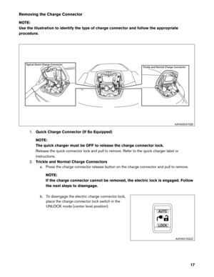
PPE. • If the charge connector is connected to the vehicle, remove it. Refer to
Removing the
Charge
Connector .
• The vehicle contains parts that contain powerful magnets. If a person who is wearing
a
pacemaker or other medical device is close to these parts, the medical device may be
affected by the magnets. Such persons must not perform work on the vehicle.
• Be sure to verify that the READY indicator is off and the high voltage system is
stopped.
•
After the high voltage system is shut down, please wait at least ten (10) minutes for
complete discharge of the high voltage capacitor. While waiting, do not operate any vehicle
functions.
NOTE:
The high voltage full discharge takes ten (10) minutes, but after five (5) minutes the voltage
has dropped below 60V.
• After shutting down the high voltage system and removing the 12V battery negative (-) terminal, wait at least three (3) minutes to discharge the air bag capacitor. Even though the
12V battery negative (-) is disconnected, the Supplemental Restraint System (SRS) air bag
maintains voltage at least three (3) minutes. During this time, there is a possibility of
sudden SRS air bag inflation due to harness short circuit or damage and it may cause
serious injuries.
• Always shut down the high voltage system before disconnecting the 12V battery. Not doing so may result in serious injury or death from electrical shock.
• The 12V system will remain active even after the 12V battery negative (-) terminal is removed while the high voltage system is active. The high voltage system is active during
any of the following conditions:
– charging indicator is turned ON
– READY indicator is turned ON
Refer to 1-1.2 Interior Component Location for location of these indicators. This is because
DC/DC
converter will not shut down and power will be supplied to the 12V system and
high voltage system continuously.
16


Number of Li-ion battery modules in the pack 48
Li-ion battery dimensions 60.91 x 46.77 x 10.3")
 .
Stabilize the vehicle with cribbing, by removing")