2013 NISSAN LEAF battery location
[x] Cancel search: battery locationPage 3 of 44
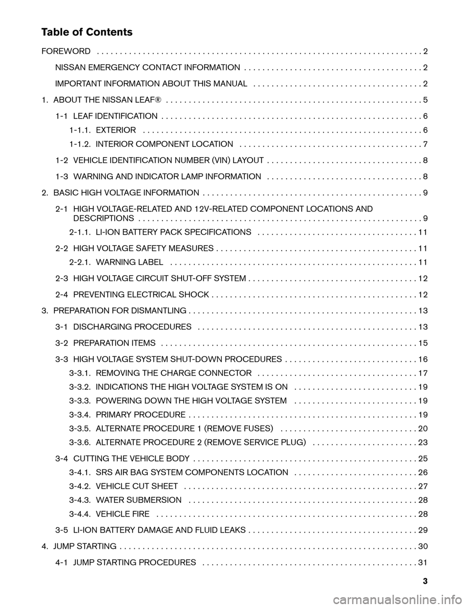
Table of Contents
FOREWORD
. . . . . . . . . . . . . . . . . . . . . . . . . . . . . . . . . . . . . . . . . . . . . . . . . . . . . . . . . . . . . . . . . . . . . . . 2
NISSAN EMERGENCY CONTACT INFORMATION . . . . . . . . . . . . . . . . . . . . . . . . . . . . . . . . . . . . . . . 2
IMPORTANT INFORMATION ABOUT THIS MANUAL . . . . . . . . . . . . . . . . . . . . . . . . . . . . . . . . . . . . . 2
1. ABOUT THE NISSAN LEAF® . . . . . . . . . . . . . . . . . . . . . . . . . . . . . . . . . . . . . . . . . . . . . . . . . . . . . . . . 5 1-1 LEAF IDENTIFICATION . . . . . . . . . . . . . . . . . . . . . . . . . . . . . . . . . . . . . . . . . . . . . . . . . . . . . . . . . 61-1.1. EXTERIOR . . . . . . . . . . . . . . . . . . . . . . . . . . . . . . . . . . . . . . . . . . . . . . . . . . . . . . . . . . . . . 6
1-1.2. INTERIOR COMPONENT LOCATION . . . . . . . . . . . . . . . . . . . . . . . . . . . . . . . . . . . . . . . . 7
1-2 VEHICLE IDENTIFICATION NUMBER (VIN) LAYOUT . . . . . . . . . . . . . . . . . . . . . . . . . . . . . . . . . . 8
1-3 WARNING AND INDICATOR LAMP INFORMATION . . . . . . . . . . . . . . . . . . . . . . . . . . . . . . . . . . 8
2. BASIC HIGH VOLTAGE INFORMATION . . . . . . . . . . . . . . . . . . . . . . . . . . . . . . . . . . . . . . . . . . . . . . . . 9 2-1 HIGH VOLTAGE-RELATED AND 12V-RELATED COMPONENT LOCATIONS AND DESCRIPTIONS . . . . . . . . . . . . . . . . . . . . . . . . . . . . . . . . . . . . . . . . . . . . . . . . . . . . . . . . . . . . . . 9
2-1.1. LI-ION BATTERY PACK SPECIFICATIONS . . . . . . . . . . . . . . . . . . . . . . . . . . . . . . . . . . . 11
2-2 HIGH VOLTAGE SAFETY MEASURES . . . . . . . . . . . . . . . . . . . . . . . . . . . . . . . . . . . . . . . . . . . . 11 2-2.1. WARNING LABEL . . . . . . . . . . . . . . . . . . . . . . . . . . . . . . . . . . . . . . . . . . . . . . . . . . . . . . 11
2-3 HIGH VOLTAGE CIRCUIT SHUT-OFF SYSTEM . . . . . . . . . . . . . . . . . . . . . . . . . . . . . . . . . . . . . 12
2-4 PREVENTING ELECTRICAL SHOCK . . . . . . . . . . . . . . . . . . . . . . . . . . . . . . . . . . . . . . . . . . . . . 12
3. PREPARATION FOR DISMANTLING . . . . . . . . . . . . . . . . . . . . . . . . . . . . . . . . . . . . . . . . . . . . . . . . . . 13 3-1 DISCHARGING PROCEDURES . . . . . . . . . . . . . . . . . . . . . . . . . . . . . . . . . . . . . . . . . . . . . . . . 13
3-2 PREPARATION ITEMS . . . . . . . . . . . . . . . . . . . . . . . . . . . . . . . . . . . . . . . . . . . . . . . . . . . . . . . . 15
3-3 HIGH VOLTAGE SYSTEM SHUT-DOWN PROCEDURES . . . . . . . . . . . . . . . . . . . . . . . . . . . . . 163-3.1. REMOVING THE CHARGE CONNECTOR . . . . . . . . . . . . . . . . . . . . . . . . . . . . . . . . . . . 17
3-3.2. INDICATIONS THE HIGH VOLTAGE SYSTEM IS ON . . . . . . . . . . . . . . . . . . . . . . . . . . . 19
3-3.3. POWERING DOWN THE HIGH VOLTAGE SYSTEM . . . . . . . . . . . . . . . . . . . . . . . . . . . 19
3-3.4. PRIMARY PROCEDURE . . . . . . . . . . . . . . . . . . . . . . . . . . . . . . . . . . . . . . . . . . . . . . . . . . 19
3-3.5. ALTERNATE PROCEDURE 1 (REMOVE FUSES) . . . . . . . . . . . . . . . . . . . . . . . . . . . . . . 20
3-3.6. ALTERNATE PROCEDURE 2 (REMOVE SERVICE PLUG) . . . . . . . . . . . . . . . . . . . . . . . 23
3-4 CUTTING THE VEHICLE BODY . . . . . . . . . . . . . . . . . . . . . . . . . . . . . . . . . . . . . . . . . . . . . . . . . 25 3-4.1. SRS AIR BAG SYSTEM COMPONENTS LOCATION . . . . . . . . . . . . . . . . . . . . . . . . . . . 26
3-4.2. VEHICLE CUT SHEET . . . . . . . . . . . . . . . . . . . . . . . . . . . . . . . . . . . . . . . . . . . . . . . . . . . 27
3-4.3. WATER SUBMERSION . . . . . . . . . . . . . . . . . . . . . . . . . . . . . . . . . . . . . . . . . . . . . . . . . . 28
3-4.4. VEHICLE FIRE . . . . . . . . . . . . . . . . . . . . . . . . . . . . . . . . . . . . . . . . . . . . . . . . . . . . . . . . . 28
3-5 LI-ION BATTERY DAMAGE AND FLUID LEAKS . . . . . . . . . . . . . . . . . . . . . . . . . . . . . . . . . . . . . 29
4. JUMP STARTING . . . . . . . . . . . . . . . . . . . . . . . . . . . . . . . . . . . . . . . . . . . . . . . . . . . . . . . . . . . . . . . . . 30 4-1 JUMP STARTING PROCEDURES . . . . . . . . . . . . . . . . . . . . . . . . . . . . . . . . . . . . . . . . . . . . . . . 31
3
Page 10 of 44
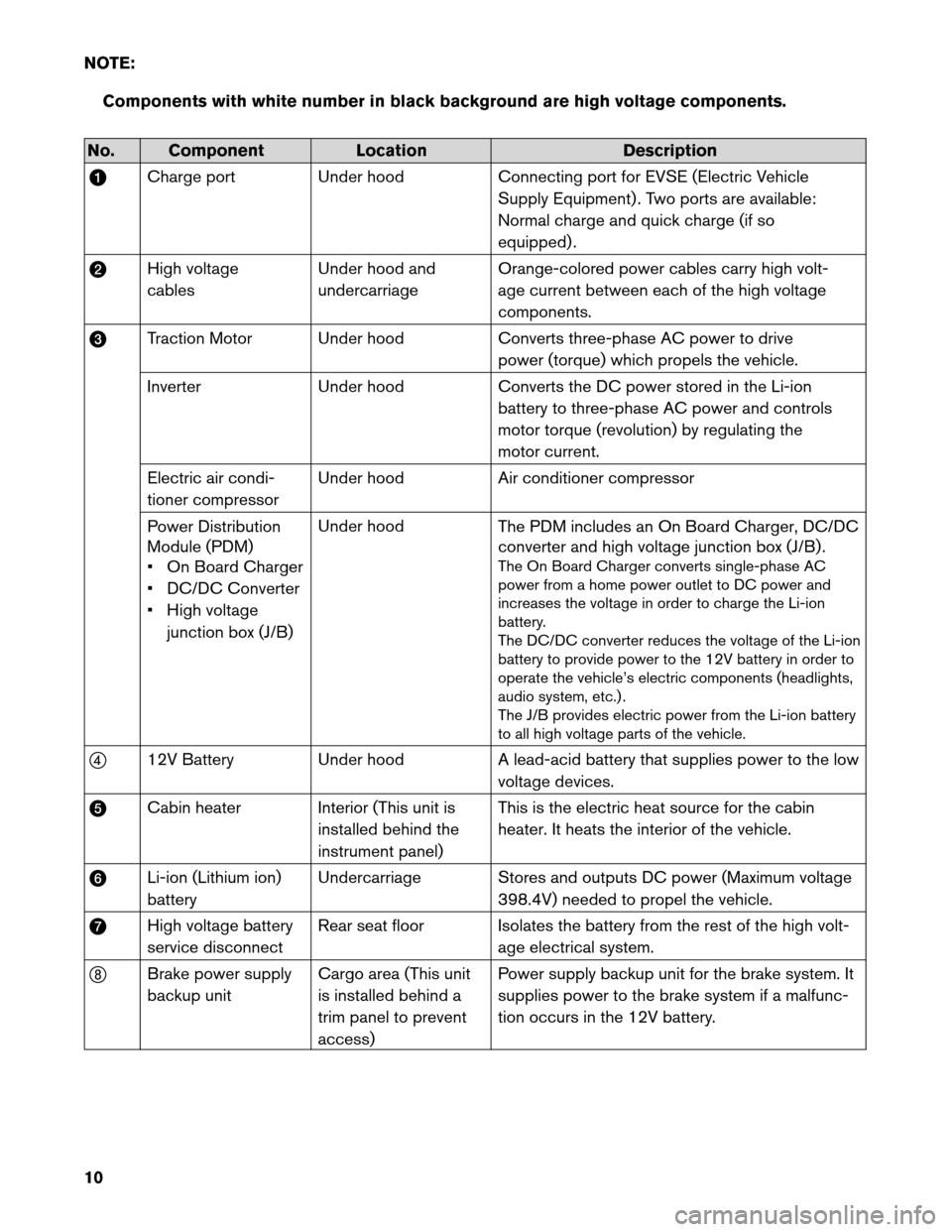
NOTE:
Components with white number in black background are high voltage components.No. Component
LocationDescription
a Charge
port Under hood Connecting port for EVSE (Electric Vehicle
Supply Equipment) . Two ports are available:
Normal charge and quick charge (if so
equipped) .
b High voltage
cables Under hood and
undercarriage Orange-colored power cables carry high volt-
age current between each of the high voltage
components.
c Traction Motor Under hood Converts three-phase AC power to drive
power (torque) which propels the vehicle.
Inverter Under hood Converts the DC power stored in the Li-ion
battery to three-phase AC power and controls
motor torque (revolution) by regulating the
motor current.
Electric air condi-
tioner compressor Under hood
Air conditioner compressor
Power Distribution
Module (PDM)
• On Board Charger
• DC/DC Converter
• High voltage junction box (J/B) Under hood
The PDM includes an On Board Charger, DC/DC
converter and high voltage junction box (J/B) .
The On Board Charger converts single-phase AC
power from a home power outlet to DC power and
increases the voltage in order to charge the Li-ion
battery.
The DC/DC converter reduces the voltage of the Li-ion
battery to provide power to the 12V battery in order to
operate the vehicle’s electric components (headlights,
audio system, etc.) .
The J/B provides electric power from the Li-ion battery
to all high voltage parts of the vehicle.
d 12V Battery Under hood A lead-acid battery that supplies power to the low
voltage devices.
e Cabin heater Interior (This unit is
installed behind the
instrument panel) This is the electric heat source for the cabin
heater. It heats the interior of the vehicle.
f Li-ion (Lithium ion)
battery Undercarriage Stores and outputs DC power (Maximum voltage
398.4V) needed to propel the vehicle.
g High voltage battery
service disconnect Rear seat floor Isolates the battery from the rest of the high volt-
age electrical system.
h Brake power supply
backup unit Cargo area (This unit
is installed behind a
trim panel to prevent
access) Power supply backup unit for the brake system. It
supplies power to the brake system if a malfunc-
tion occurs in the 12V battery.
10
Page 16 of 44
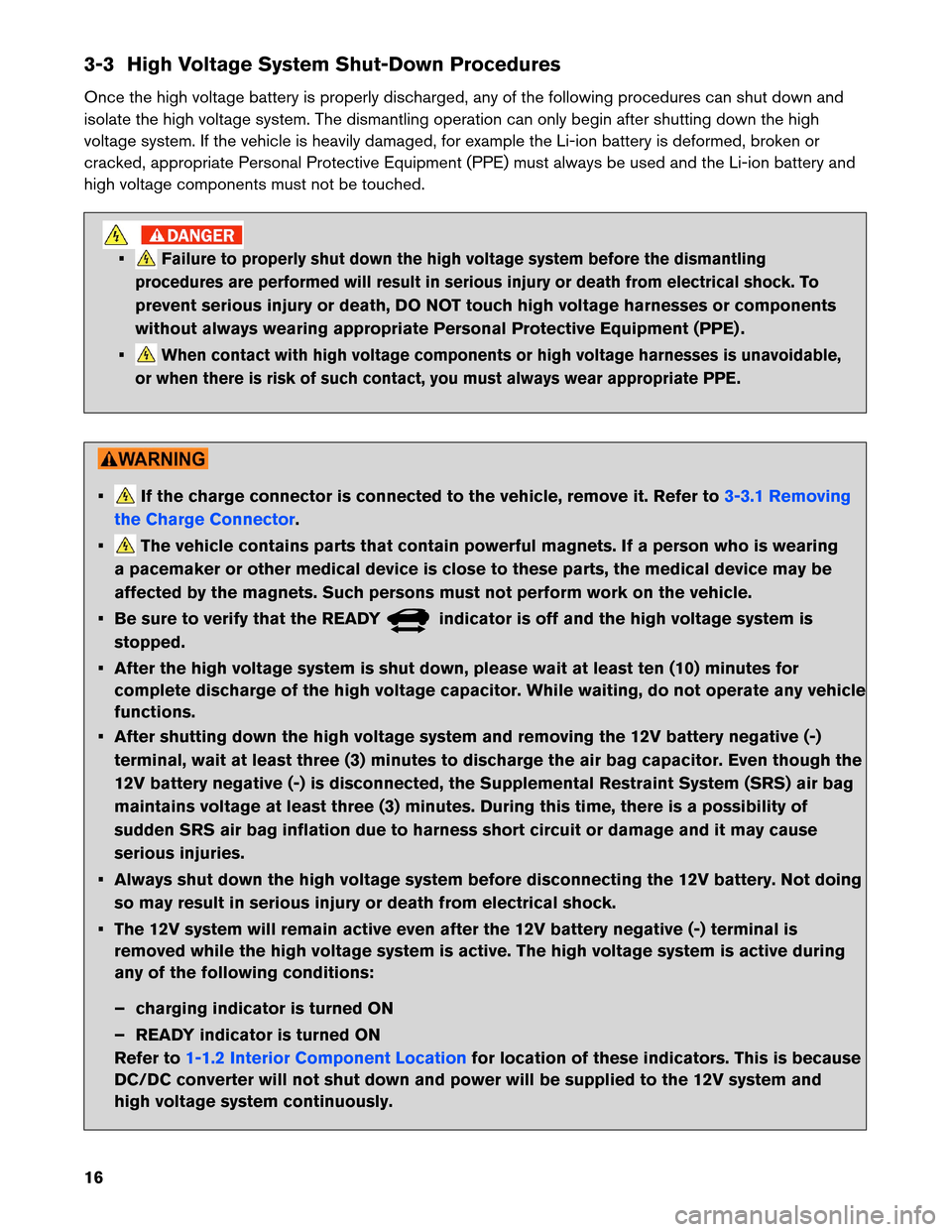
3-3 High Voltage System Shut-Down Procedures
Once
the high voltage battery is properly discharged, any of the following procedures can shut down and
isolate the high voltage system. The dismantling operation can only begin after shutting down the high
voltage system. If the vehicle is heavily damaged, for example the Li-ion battery is deformed, broken or
cracked, appropriate Personal Protective Equipment (PPE) must always be used and the Li-ion battery and
high voltage components must not be touched. •
Failure to properly shut down the high voltage system before the dismantling
procedures are performed will result in serious injury or death from electrical shock.
To
prevent serious injury or death, DO NOT touch high voltage harnesses or components
without always wearing appropriate Personal Protective Equipment (PPE) .
•
When contact with high voltage components or high voltage harnesses is unavoidable,
or when there is risk of such contact, you must always wear appropriate PPE. • If the charge connector is connected to the vehicle, remove it. Refer to
3-3.1 Removing
the
Charge Connector .
• The vehicle contains parts that contain powerful magnets. If a person who is wearing
a
pacemaker or other medical device is close to these parts, the medical device may be
affected by the magnets. Such persons must not perform work on the vehicle.
• Be sure to verify that the READY indicator is off and the high voltage system is
stopped.
•
After the high voltage system is shut down, please wait at least ten (10) minutes for
complete discharge of the high voltage capacitor. While waiting, do not operate any vehicle
functions.
• After shutting down the high voltage system and removing the 12V battery negative (-) terminal, wait at least three (3) minutes to discharge the air bag capacitor. Even though the
12V battery negative (-) is disconnected, the Supplemental Restraint System (SRS) air bag
maintains voltage at least three (3) minutes. During this time, there is a possibility of
sudden SRS air bag inflation due to harness short circuit or damage and it may cause
serious injuries.
• Always shut down the high voltage system before disconnecting the 12V battery. Not doing so may result in serious injury or death from electrical shock.
• The 12V system will remain active even after the 12V battery negative (-) terminal is removed while the high voltage system is active. The high voltage system is active during
any of the following conditions:
– charging indicator is turned ON
– READY indicator is turned ON
Refer to 1-1.2 Interior Component Location
for location of these indicators. This is because
DC/DC
converter will not shut down and power will be supplied to the 12V system and
high voltage system continuously.
16
Page 26 of 44
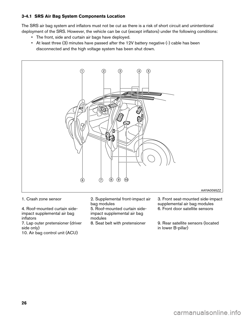
3-4.1 SRS Air Bag System Components Location
The
SRS air bag system and inflators must not be cut as there is a risk of short circuit and unintentional
deployment of the SRS. However, the vehicle can be cut (except inflators) under the following conditions: • The front, side and curtain air bags have deployed.
• At least three (3) minutes have passed after the 12V battery negative (-) cable has beendisconnected and the high voltage system has been shut down.
1. Crash zone sensor 2. Supplemental front-impact air
bag modules 3. Front seat-mounted side-impact
supplemental air bag modules
4. Roof-mounted curtain side-
impact supplemental air bag
inflators 5. Roof-mounted curtain side-
impact supplemental air bag
modules6. Front door satellite sensors
7. Lap outer pretensioner (driver
side only) 8. Seat belt with pretensioner 9. Rear satellite sensors (located
in lower B-pillar)
10. Air bag control unit (ACU) 11 2 3 4 5
6 7 8 9 10
AAYIA0095ZZ
26
Page 34 of 44
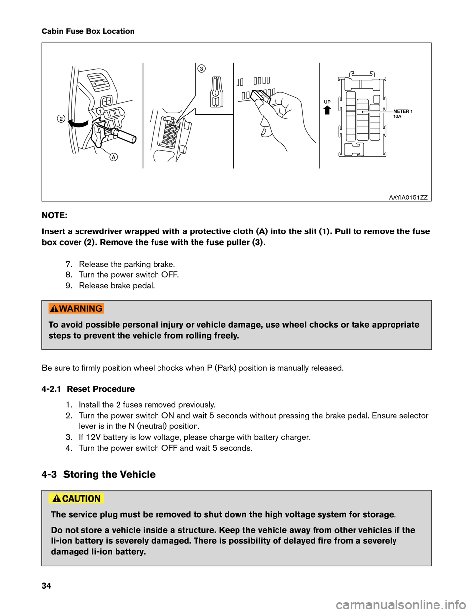
Cabin Fuse Box Location
NO
TE:
Insert a screwdriver wrapped with a protective cloth (A) into the slit (1) . Pull to remove the fuse
box cover (2) . Remove the fuse with the fuse puller (3) .
7. Release the parking brake.
8. Turn the power switch OFF.
9. Release brake pedal. To avoid possible personal injury or vehicle damage, use wheel chocks or take appropriate
steps
to prevent the vehicle from rolling freely.
Be sure to firmly position wheel chocks when P (Park) position is manually released.
4-2.1 Reset Procedure 1. Install the 2 fuses removed previously.
2. Turn the power switch ON and wait 5 seconds without pressing the brake pedal. Ensure selectorlever is in the N (neutral) position.
3. If 12V battery is low voltage, please charge with battery charger.
4. Turn the power switch OFF and wait 5 seconds.
4-3 Storing the Vehicle The service plug must be removed to shut down the high voltage system for storage.
Do
not store a vehicle inside a structure. Keep the vehicle away from other vehicles if the
li-ion battery is severely damaged. There is possibility of delayed fire from a severely
damaged li-ion battery. UP
METER 1
10A
11 3
2
A
AAYIA0151ZZ
34