2013 NISSAN GT-R change time
[x] Cancel search: change timePage 3 of 346
WHEN READING THE MANUAL
This manual includes information for all
options available on this model. Therefore,
you may find some information that does
not apply to your vehicle.
All information, specifications and illustrations in
this manual are those in effect at the time of
printing. NISSAN reserves the right to change
specifications or design at any time without
notice.
IMPORTANT INFORMATION ABOUT
THIS MANUAL
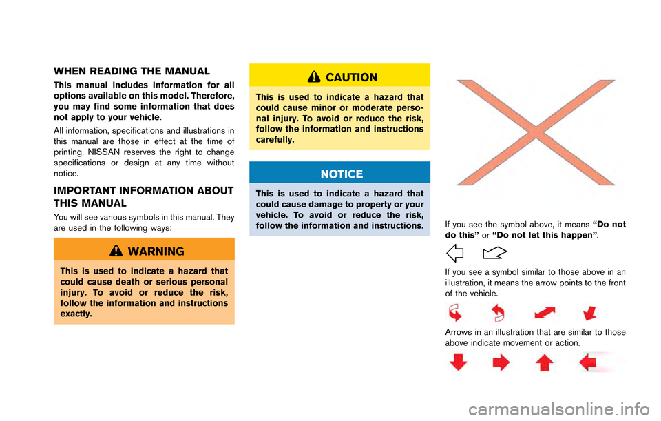
You will see various symbols in this manual. They
are used in the following ways:
WARNING
This is used to indicate a hazard that
could cause death or serious personal
injury. To avoid or reduce the risk,
follow the information and instructions
exactly.
CAUTION
This is used to indicate a hazard that
could cause minor or moderate perso-
nal injury. To avoid or reduce the risk,
follow the information and instructions
carefully.
NOTICE
This is used to indicate a hazard that
could cause damage to property or your
vehicle. To avoid or reduce the risk,
follow the information and instructions.
If you see the symbol above, it means“Do not
do this” or“Do not let this happen” .
If you see a symbol similar to those above in an
illustration, it means the arrow points to the front
of the vehicle.
Arrows in an illustration that are similar to those
above indicate movement or action.
Page 16 of 346
TRANSMISSION SETTINGS
The design of the clutch and transmission
requires inspection and adjustment of the clutch
and shift forks by a GT-R certified NISSAN
dealer at the recommended intervals. Depend-
ing on the driving conditions, more frequent
adjustments may be necessary to help maximize
vehicle performance.
CHECKING THE EXHAUST FIN-
ISHER AND REAR BUMPER
CLEARANCE
Clearance between the enlarged-diameter ex-
haust finisher and the rear bumper is realized by
using highly rigid exhaust mount rubber to
control rear muffler vibration. The clearance
between the exhaust finisher and the rear
bumper may alter as the exhaust mount rubber
changes shape due to vibration, passage of time
and high exhaust temperature during high
performance driving. Therefore, inspection of
the clearance is necessary during the GT-R
special inspection and when engaging in
performance driving.
INCREASE TIGHTENING OF THE
STRUT SUPPORT BAR ATTACH-
MENT SECTION WITH THE SHOCK
ABSORBER
During the first GT-R special inspection (after
1,000 miles) , the strut support bar attachment
bracket and shock absorber (each one on the
left and right sides) must be tightened to the
specified tightening specification. The strut
support bar attachment bracket and shock
absorber (each one on the left and right sides)
must be tightened to the specified tightening
specification 300-600 miles (500-1,000 km)
after the support bar or shock absorber have
been removed or installed.
(
“Engine compartment check locations”
page 8-8)
NOTICE
Follow these recommendations to ob-
tain maximum engine performance and
ensure the future reliability and econo-
my of your new vehicle. Failure to
follow these recommendations may
result in shortened engine life and
reduced vehicle performance.
Please observe the following types of driving
until the mileage shown below has been
reached.
Until 300 miles (500 km):
. Do not depress the accelerator pedal more
than halfway and avoid rapid acceleration.
. Drive with the engine speed kept at less
than 3,500 RPM.
. Avoid unnecessary quick steering, abrupt
braking and driving on poor roads.
300 to 600 miles (500 to 1,000 km):
. Avoid rapid acceleration in a low gear (1st to
3rd gears) with the accelerator pedal fully
depressed. Depress the pedal slowly.
. Avoid unnecessary quick steering and
abrupt braking.
GT-R OverviewGTR-9
BREAK-IN SCHEDULE
Page 36 of 346
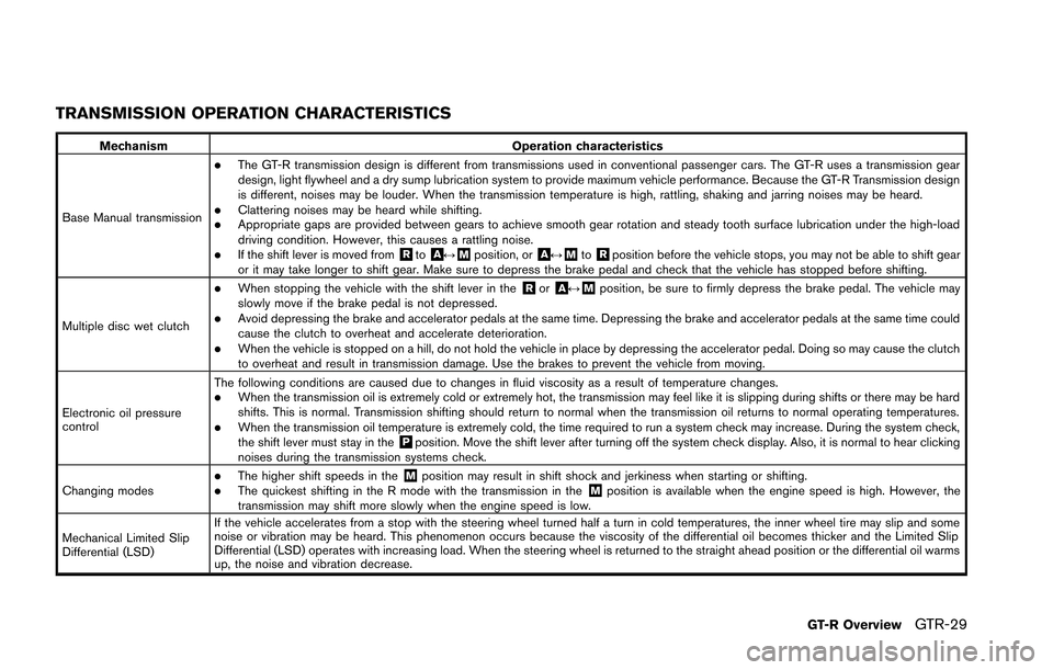
TRANSMISSION OPERATION CHARACTERISTICS
MechanismOperation characteristics
Base Manual transmission
.The GT-R transmission design is different from transmissions used in conventional passenger cars. The GT-R uses a transmission gear
design, light flywheel and a dry sump lubrication system to provide maximum vehicle performance. Because the GT-R Transmission design
is different, noises may be louder. When the transmission temperature is high, rattling, shaking and jarring noises may be heard.
.Clattering noises may be heard while shifting..Appropriate gaps are provided between gears to achieve smooth gear rotation and steady tooth surface lubrication under the high-load
driving condition. However, this causes a rattling noise.
.If the shift lever is moved from&Rto&A↔&Mposition, or&A↔&Mto&Rposition before the vehicle stops, you may not be able to shift gear
or it may take longer to shift gear. Make sure to depress the brake pedal and check that the vehicle has stopped before shifting.
Multiple disc wet clutch
.When stopping the vehicle with the shift lever in the&Ror&A↔&Mposition, be sure to firmly depress the brake pedal. The vehicle may
slowly move if the brake pedal is not depressed.
.Avoid depressing the brake and accelerator pedals at the same time. Depressing the brake and accelerator pedals at the same time could
cause the clutch to overheat and accelerate deterioration.
.When the vehicle is stopped on a hill, do not hold the vehicle in place by depressing the accelerator pedal. Doing so may cause the clutch
to overheat and result in transmission damage. Use the brakes to prevent the vehicle from moving.
Electronic oil pressure
control The following conditions are caused due to changes in fluid viscosity as a result of temperature changes.
.When the transmission oil is extremely cold or extremely hot, the transmission may feel like it is slipping during shifts or there may be hard
shifts. This is normal. Transmission shifting should return to normal when the transmission oil returns to normal operating temperatures.
.When the transmission oil temperature is extremely cold, the time required to run a system check may increase. During the system check,
the shift lever must stay in the&Pposition. Move the shift lever after turning off the system check display. Also, it is normal to hear clicking
noises during the transmission systems check.
Changing modes
.The higher shift speeds in the&Mposition may result in shift shock and jerkiness when starting or shifting..The quickest shifting in the R mode with the transmission in the&Mposition is available when the engine speed is high. However, the
transmission may shift more slowly when the engine speed is low.
Mechanical Limited Slip
Differential (LSD) If the vehicle accelerates from a stop with the steering wheel turned half a turn in cold temperatures, the inner wheel tire may slip and some
noise or vibration may be heard. This phenomenon occurs because the viscosity of the differential oil becomes thicker and the Limited Slip
Differential (LSD) operates with increasing load. When the steering wheel is returned to the straight ahead position or the differential oil warms
up, the noise and vibration decrease.
GT-R OverviewGTR-29
Page 56 of 346
WARNING
.Every person who drives or rides in
this vehicle should use a seat belt at
all times. Children should be prop-
erly restrained in the rear seat and,
if appropriate, in a child restraint.
. The seat belt should be properly
adjusted to a snug fit. Failure to do
so may reduce the effectiveness of
the entire restraint system and in-
crease the chance or severity of
injury in an accident. Serious injury
or death can occur if the seat belt is
not worn properly.
. Always route the shoulder belt over
your shoulder and across your
chest. Never put the belt behind
your back, under your arm or across
your neck. The belt should be away
from your face and neck, but not
falling off your shoulder.
. Position the lap belt as low and
snug as possible AROUND THE
HIPS, NOT THE WAIST. A lap belt
worn too high could increase the
risk of internal injuries in an acci-
dent. .
Be sure the seat belt tongue is
securely fastened to the proper
buckle.
. Do not wear the seat belt inside out
or twisted. Doing so may reduce its
effectiveness.
. Do not allow more than one person
to use the same seat belt.
. Never carry more people in the
vehicle than there are seat belts.
. If the seat belt warning light glows
continuously while the ignition is
turned ON with all doors closed and
all seat belts fastened, it may in-
dicate a malfunction in the system.
Have the system checked by a GT-R
certified NISSAN dealer.
. No changes should be made to the
seat belt system. For example, do
not modify the seat belt, add mate-
rial, or install devices that may
change the seat belt routing or
tension. Doing so may affect the
operation of the seat belt system.
Modifying or tampering with the
seat belt system may result in
serious personal injury. .
Once a seat belt pretensioner has
activated, it cannot be reused and
must be replaced together with the
retractor. See a GT-R certified
NISSAN dealer.
. Removal and installation of the
pretensioner system components
should be done by a GT-R certified
NISSAN dealer.
. All seat belt assemblies, including
retractors and attaching hardware,
should be inspected after any colli-
sion by a GT-R certified NISSAN
dealer. NISSAN recommends that
all seat belt assemblies in use
during a collision be replaced un-
less the collision was minor and the
belts show no damage and continue
to operate properly.
Seat belt assemblies not in use
during a collision should also be
inspected and replaced if either
damage or improper operation is
noted.
. All child restraints and attaching
hardware should be inspected after
any collision. Always follow the
restraint manufacturer’s inspection
Safety — Seats, seat belts and supplemental restraint system1-7
Page 109 of 346
2-14Instruments and controls
after the system check is finished.
Release the button and push it again
to operate the shift lever.
. During winter or at other times when
the temperature is extremely low,
changes in the hydraulic response
characteristics may increase the
amount of time that is required for the
system check. During the system check,
a thudding operating noise may occur
or the engine speed may decrease,
however this does not indicate that
there is a malfunction.
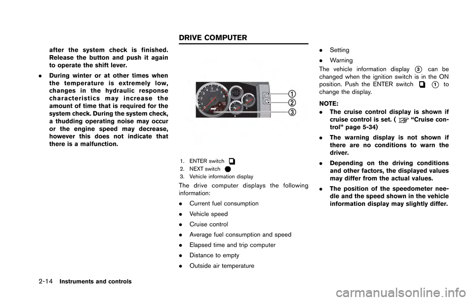
1. ENTER switch2. NEXT switch3. Vehicle information display
The drive computer displays the following
information:
.Current fuel consumption
. Vehicle speed
. Cruise control
. Average fuel consumption and speed
. Elapsed time and trip computer
. Distance to empty
. Outside air temperature .
Setting
. Warning
The vehicle information display
*3can be
changed when the ignition switch is in the ON
position. Push the ENTER switch
*1to
change the display.
NOTE:
. The cruise control display is shown if
cruise control is set. (
“Cruise con-
trol” page 5-34)
. The warning display is not shown if
there are no conditions to warn the
driver.
. Depending on the driving conditions
and other factors, the displayed values
may differ from the actual values.
. The position of the speedometer nee-
dle and the speed shown in the vehicle
information display may slightly differ.
DRIVE COMPUTER
Page 114 of 346
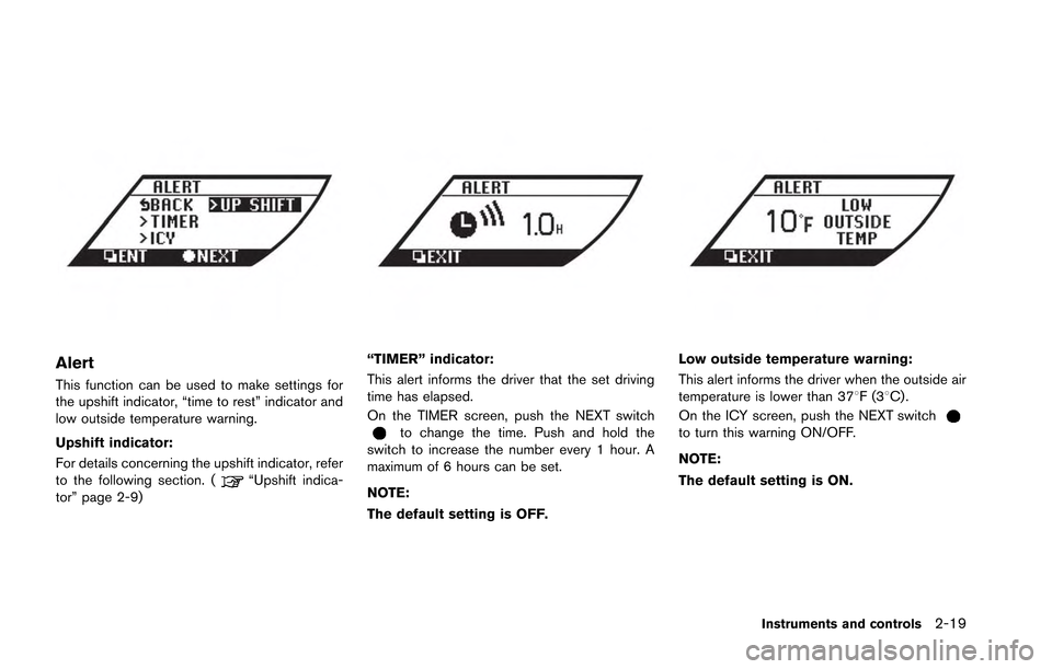
Alert
This function can be used to make settings for
the upshift indicator, “time to rest” indicator and
low outside temperature warning.
Upshift indicator:
For details concerning the upshift indicator, refer
to the following section. (
“Upshift indica-
tor” page 2-9)
“TIMER” indicator:
This alert informs the driver that the set driving
time has elapsed.
On the TIMER screen, push the NEXT switch
to change the time. Push and hold the
switch to increase the number every 1 hour. A
maximum of 6 hours can be set.
NOTE:
The default setting is OFF.
Low outside temperature warning:
This alert informs the driver when the outside air
temperature is lower than 378F(3 8C) .
On the ICY screen, push the NEXT switch
to turn this warning ON/OFF.
NOTE:
The default setting is ON.
Instruments and controls2-19
Page 140 of 346
5. Confirm that the security indicator lightcomes on. The security indicator light stays
on for about 30 seconds. The vehicle
security system is now pre-armed. After
about 30 seconds the vehicle security
system automatically shifts into the armed
phase. The security light begins to flash
once every approximately 3 seconds. If,
during this 30-second pre-arm time period,
the door is unlocked, or the ignition switch is
pushed to ACC or ON, the system will not
arm.
Even when the driver and/or passengers
are in the vehicle, the system will activate
with all doors, hood, and trunk lid locked
with the ignition switch in the LOCK
position. When pushing the ignition switch
to the ACC or ON position, the system will
be released.
Vehicle security system activation
The vehicle security system will give the follow-
ing alarm:
. The headlights blink and the horn sounds
intermittently.
. The alarm automatically turns off after
approximately 1 minute. However, the alarm
reactivates if the vehicle is tampered with
again. The alarm is activated by:
.
Opening the door or the trunk lid without
using the button on the Intelligent Key, the
door handle request switch or the mechan-
ical key. (Even if the door is opened by
releasing the door inside lock knob, the
alarm will activate.)
. Opening the hood.
How to stop an activated alarm
The alarm will stop by:
.Unlocking a door by pushing the UNLOCK
button on the Intelligent Key.
. Unlocking a door by pushing the door
handle request switch.
. Pushing the ignition switch to the ACC or
ON position.
If the system does not operate as de-
scribed above, have it checked by a GT-R
certified NISSAN dealer.
NISSAN VEHICLE IMMOBILIZER
SYSTEM
The NISSAN Vehicle Immobilizer System will not
allow the engine to start without the use of the
registered Intelligent Key. Never leave these
keys in the vehicle. FCC Notice:
For USA:
This device complies with Part 15 of the
FCC Rules. Operation is subject to the
following two conditions: (1) This device
may not cause harmful interference, and
(2) this device must accept any interfer-
ence received, including interference that
may cause undesired operation.
Note: Changes or modifications not ex-
pressly approved by the party responsible
for compliance could void the user’s
authority to operate the equipment.
For Canada:
This device complies with RSS-210 of
Industry Canada. Operation is subject to
the following two conditions: (1) this
device may not cause interference, and
(2) this device must accept any interfer-
ence, including interference that may
cause undesired operation of the device.
Instruments and controls2-45
Page 147 of 346
2-52Instruments and controls
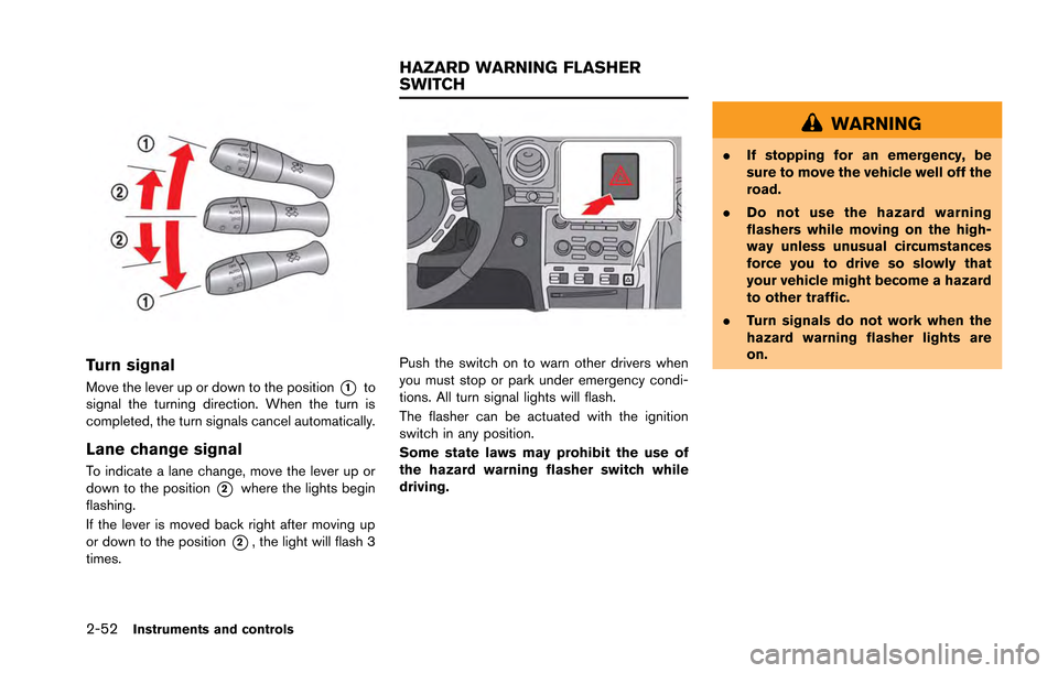
Turn signal
Move the lever up or down to the position*1to
signal the turning direction. When the turn is
completed, the turn signals cancel automatically.
Lane change signal
To indicate a lane change, move the lever up or
down to the position
*2where the lights begin
flashing.
If the lever is moved back right after moving up
or down to the position
*2, the light will flash 3
times.
Push the switch on to warn other drivers when
you must stop or park under emergency condi-
tions. All turn signal lights will flash.
The flasher can be actuated with the ignition
switch in any position.
Some state laws may prohibit the use of
the hazard warning flasher switch while
driving.
WARNING
. If stopping for an emergency, be
sure to move the vehicle well off the
road.
. Do not use the hazard warning
flashers while moving on the high-
way unless unusual circumstances
force you to drive so slowly that
your vehicle might become a hazard
to other traffic.
. Turn signals do not work when the
hazard warning flasher lights are
on.
HAZARD WARNING FLASHER
SWITCH