2013 NISSAN GT-R warning
[x] Cancel search: warningPage 31 of 346
GTR-24GT-R Overview
REFUELING PRECAUTIONS
WARNING
Do not attempt to top off the fuel tank
after the fuel pump nozzle shuts off
automatically. Continued refueling may
cause fuel overflow, resulting in fuel
spray and possibly a fire. The fuel tank
is full at the first automatic shutoff.
To maximize vehicle performance, the fuel tank is
located as low as possible to lower the vehicle
center of gravity. The tank is also divided into
two parts. This fuel tank design causes higher
pressures inside the tank than other vehicles so
fuel spillage is possible by trying to top off the
fuel tank after automatic shutoff.
The fuel tank pressure is higher when the vehicle
is hot, especially if the tank is more than half full.
If the cap is opened when the vehicle is hot, it
may cause fuel spray and there may be a hissing
noise. Open the cap slowly, releasing the
pressure from the tank gradually. Also, if the
vehicle is refueled when the vehicle is hot, the
fuel pump may automatically shut off before the
tank is full. This does not indicate that there is a
malfunction. Refuel slowly or refuel after the vehicle has cooled.
GASOLINE SMELL
The fuel temperature is higher when the vehicle
is hot. This may cause a gasoline smell from the
vehicle. This does not indicate that there is a
malfunction. The smell will go away when the
fuel temperature has cooled.
OUTSIDE TEMPERATURE DISPLAY
INDICATES HIGHER TEMPERATURE
Heat from the engine compartment, radiator and
intercoolers can affect the outside temperature
display. The outside temperature display may
indicate a higher than actual temperature while
driving or stopped. This is normal.
IDLE SPEED IS NOT STEADY
The idle speed may not be steady when the
engine compartment is extremely hot. This is
normal. The engine speed will be steady when
the engine cools down.
In this case, the Malfunction Indicator Light (MIL)
may come on. After a few driving trips, the MIL
should turn off. If the light remains on after a few
driving trips, have the vehicle inspected by a
GT-R certified NISSAN dealer.
ENGINE SPEED IS RESTRICTED
To help protect the engine, the maximum engine
speed is automatically controlled in the following
conditions:
.
Revving the engine with the shift lever in the
&Por&Nposition: The maximum engine
speed is 5,000 RPM
. Revving the engine when the engine oil is at
a low (below 328F(0 8C)) or extremely high
(over 2758 F (1358C)) temperature: The
maximum engine speed is 4,000 RPM (The
&Mposition will automatically change to the
&Aposition.)
ENGINE OUTPUT
High altitude
To protect the engine, engine output is con-
trolled so that it does not increase at altitudes
4,922 ft (1,500 meters) or higher.
Engine output according to the
coolant temperature
The engine output is controlled at a low level
when the engine coolant temperature is lower
than approximately 1588F (708C) or higher than
2308F (1108C). This is not a malfunction.
If the temperature is lower than approximately
GT-R SPECIFIC VEHICLE
CHARACTERISTICS
Page 32 of 346
1588F (708C) , drive the vehicle until it reaches
normal operating temperature. If the temperature
is higher than 2308F (1108C), perform cool-
down driving procedure. (
“Cool down”
page GTR-13) When the temperature of the
engine coolant is between 1588F (708C) and
2308F (1108C) , the engine output returns to
normal.
DISTORTION OF REAR SPOILER
When the vehicle is parked in direct sunlight on
a hot day, the center of the rear spoiler may
become distorted. This is normal. When the
surface temperature of the rear spoiler is
reduced, the shape of the spoiler should return
to normal.
UNEVEN WEAR OF TIRES
The GT-R is equipped with high performance,
low profile, run-flat tires that are optimized for
performance and handling. The life of these tires
will be less than those of tires installed on a
typical vehicle, and you are likely to experience
uneven tire wear and tire noise regardless of the
type of tire used.
NOISES ARE HEARD WHILE DRIV-
ING
. The GT-R brake pads use material that
provides a high amount of braking power
even in high temperatures. This material can
cause an intermittent screeching noise just
before the vehicle comes to a stop when the
brakes are gently applied. The noise de-
creases as the brake pads wear. However,
the additional brake pad break-in or repla-
cing the cross spring may decrease the
noise. Contact a GT-R certified NISSAN
dealer.
. A screeching noise may be heard when the
brake pedal is depressed:
— When driving the vehicle for the first time
in the morning,
— After leaving the vehicle parked for extended periods of time, or
— When the vehicle is damp following rain showers or washing the vehicle.
These sounds are normal. The noise is
caused when the brake pads absorb moist-
ure, and the noise stops after the brake is
applied several times.
. A screeching noise may also be heard when
the brake pedal is depressed: — When repeatedly applying gentle brak-
ing, especially on a curve at a low speed,
or
— When the brake rotors have circular scores with the brake temperature high.
WARNING
Follow the instructions below when
parking the vehicle to help prevent the
brake rotor and brake pads from rust-
ing together. Failure to follow the
instructions could cause the rotor and
pads to rust together. If the rotor and
pads rust together, there may be a
popping noise and some vibration
when the vehicle is driven, a wheel
may not roll correctly, or the brake pads
could be damaged. If the pads are
damaged, this may reduce the effec-
tiveness of the brake system which
could cause a collision, serious perso-
nal injury or death.
. The GT-R uses brake pad materials that
have high metallic content. The brake pad
material helps maintain braking performance
in a wide range of weather and driving
conditions.
GT-R OverviewGTR-25
Page 38 of 346
 ........................................................................\
... 0-2Front .......................")
0 Illustrated table of contents
Seats, seat belts and Supplemental Restraint
System (SRS) ........................................................................\
... 0-2Front ........................................................................\
.............. 0-2
Rear ........................................................................\
............... 0-3
Exterior ........................................................................\
................ 0-4 Front ........................................................................\
.............. 0-4
Rear ........................................................................\
............... 0-5 Passenger compartment ........................................................ 0-6
Cockpit ........................................................................\
............... 0-7
Instrument panel ...................................................................... 0-8
Meters and gauges ................................................................. 0-9
Engine compartment ........................................................... 0-10
Warning and indicator lights ............................................. 0-11
Page 45 of 346
0-8Illustrated table of contents
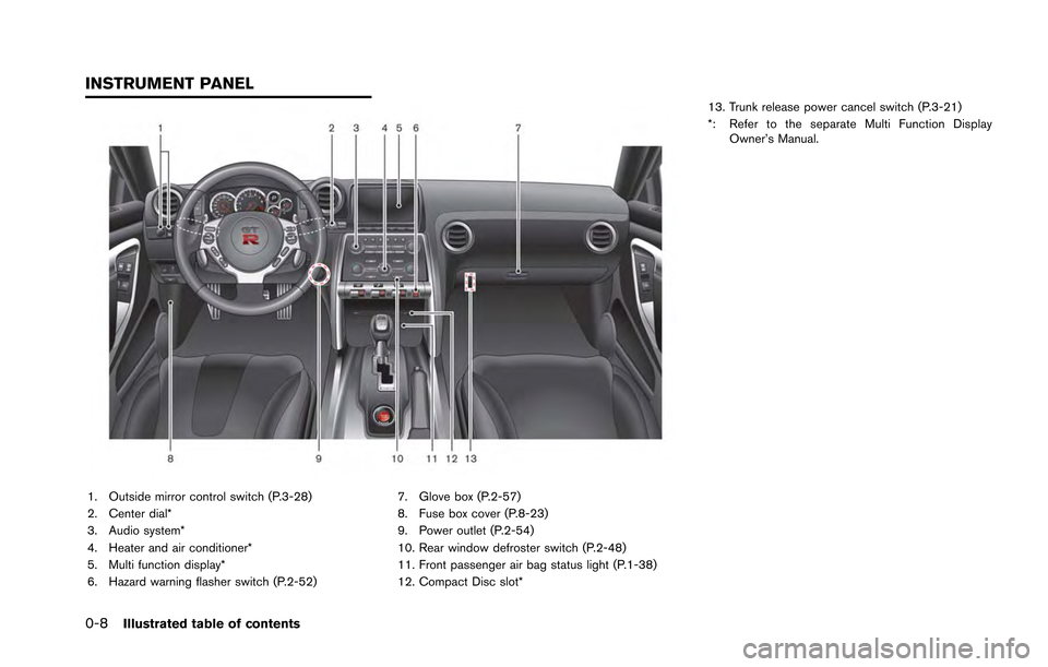
1. Outside mirror control switch (P.3-28)
2. Center dial*
3. Audio system*
4. Heater and air conditioner*
5. Multi function display*
6. Hazard warning flasher switch (P.2-52)7. Glove box (P.2-57)
8. Fuse box cover (P.8-23)
9. Power outlet (P.2-54)
10. Rear window defroster switch (P.2-48)
11. Front passenger air bag status light (P.1-38)
12. Compact Disc slot*13. Trunk release power cancel switch (P.3-21)
*: Refer to the separate Multi Function Display
Owner’s Manual.
INSTRUMENT PANEL
Page 48 of 346
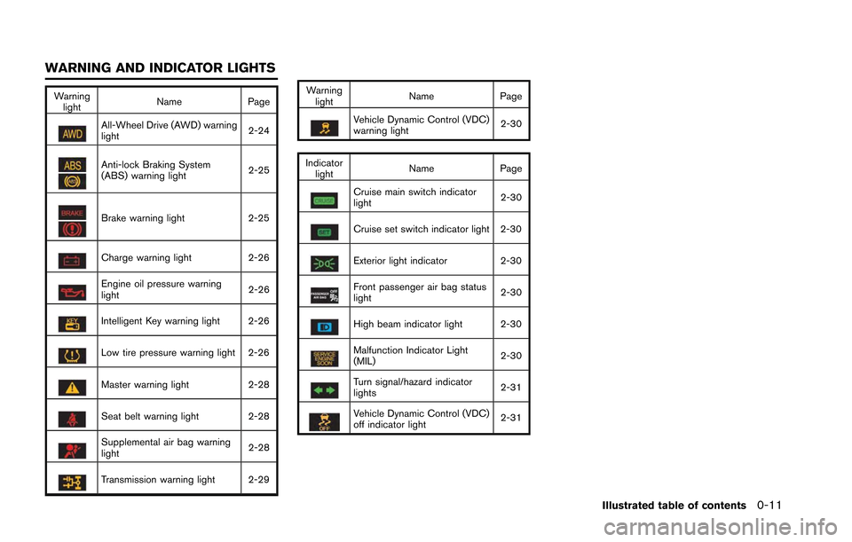
Warninglight Name
Page
All-Wheel Drive (AWD) warning
light 2-24
Anti-lock Braking System
(ABS) warning light2-25
Brake warning light
2-25
Charge warning light 2-26
Engine oil pressure warning
light 2-26
Intelligent Key warning light 2-26
Low tire pressure warning light 2-26
Master warning light
2-28
Seat belt warning light 2-28
Supplemental air bag warning
light 2-28
Transmission warning light 2-29 Warning
light Name
Page
Vehicle Dynamic Control (VDC)
warning light 2-30
Indicator light Name
Page
Cruise main switch indicator
light 2-30
Cruise set switch indicator light 2-30
Exterior light indicator
2-30
Front passenger air bag status
light 2-30
High beam indicator light 2-30
Malfunction Indicator Light
(MIL)2-30
Turn signal/hazard indicator
lights
2-31
Vehicle Dynamic Control (VDC)
off indicator light2-31
Illustrated table of contents0-11
WARNING AND INDICATOR LIGHTS
Page 50 of 346

1 Safety — Seats, seat belts and supple-mental restraint system
Seats ........................................................................\
................... 1-2
Front seats ........................................................................\
... 1-3
Head restraints ................................................................... 1-5
Seat belts ........................................................................\
........... 1-6 Precautions on seat belt usage ...................................... 1-6
Pregnant women ................................................................ 1-8
Injured persons ................................................................... 1-8
Three-point type seat belt with retractor ..................... 1-8
Seat belt extenders ......................................................... 1-12
Seat belt maintenance ................................................... 1-12
Child safety ........................................................................\
..... 1-12 Infants ........................................................................\
......... 1-13
Small children ................................................................... 1-13
Larger children ................................................................. 1-13
Child restraints ....................................................................... 1-14 Precautions on child restraints .................................... 1-14
Lower Anchors and Tethers for CHildren
System (LATCH) ............................................................. 1-16
Rear-facing child restraint installation
using LATCH .................................................................... 1-18 Rear-facing child restraint installation using the
seat belts ........................................................................\
. 1-20
Forward-facing child restraint installation
using LATCH .................................................................. 1-22
Forward-facing child restraint installation using the
seat belts ........................................................................\
. 1-24
Installing top tether strap ............................................ 1-27
Booster seats ................................................................. 1-28
Supplemental restraint system .......................................... 1-31 Precautions on supplemental restraint system ...... 1-31
NISSAN Advanced Air Bag System
(front seats) .................................................................... 1-37
Front seat-mounted side-impact supplemental
air bag and roof-mounted curtain side-impact
supplemental air bag systems ................................... 1-41
Seat belts with pretensioners (front seats) ............ 1-42
Supplemental air bag warning labels ...................... 1-43
Supplemental air bag warning light ......................... 1-44
Repair and replacement procedure ......................... 1-44
Page 51 of 346
1-2Safety — Seats, seat belts and supplemental restraint system
WARNING
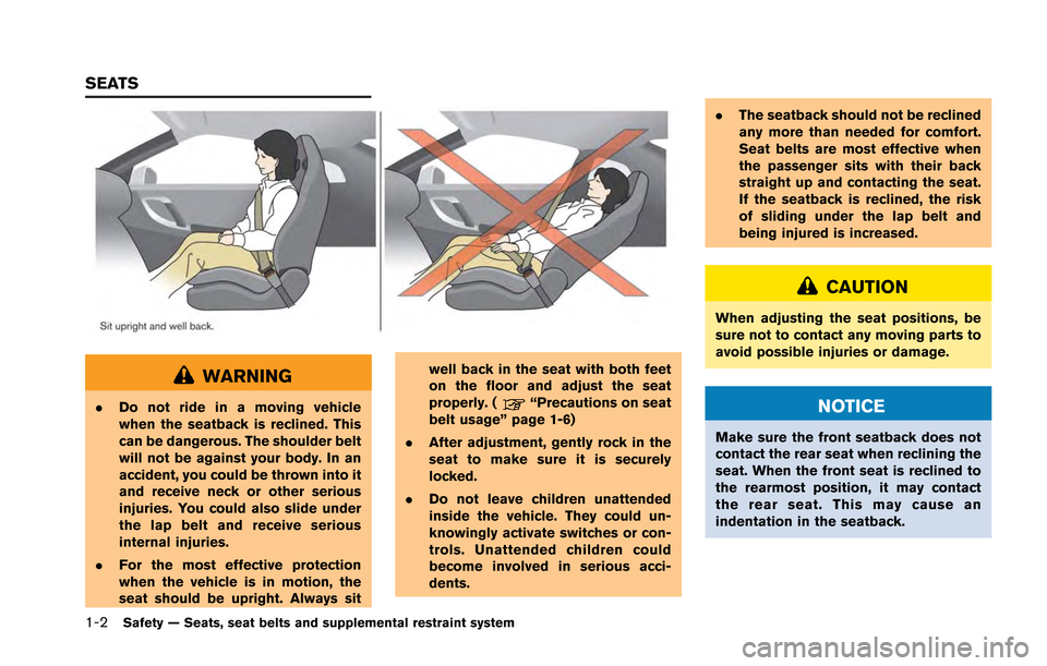
.Do not ride in a moving vehicle
when the seatback is reclined. This
can be dangerous. The shoulder belt
will not be against your body. In an
accident, you could be thrown into it
and receive neck or other serious
injuries. You could also slide under
the lap belt and receive serious
internal injuries.
. For the most effective protection
when the vehicle is in motion, the
seat should be upright. Always sit well back in the seat with both feet
on the floor and adjust the seat
properly. (“Precautions on seat
belt usage” page 1-6)
. After adjustment, gently rock in the
seat to make sure it is securely
locked.
. Do not leave children unattended
inside the vehicle. They could un-
knowingly activate switches or con-
trols. Unattended children could
become involved in serious acci-
dents. .
The seatback should not be reclined
any more than needed for comfort.
Seat belts are most effective when
the passenger sits with their back
straight up and contacting the seat.
If the seatback is reclined, the risk
of sliding under the lap belt and
being injured is increased.
CAUTION
When adjusting the seat positions, be
sure not to contact any moving parts to
avoid possible injuries or damage.
NOTICE
Make sure the front seatback does not
contact the rear seat when reclining the
seat. When the front seat is reclined to
the rearmost position, it may contact
the rear seat. This may cause an
indentation in the seatback.
SEATS
Page 54 of 346
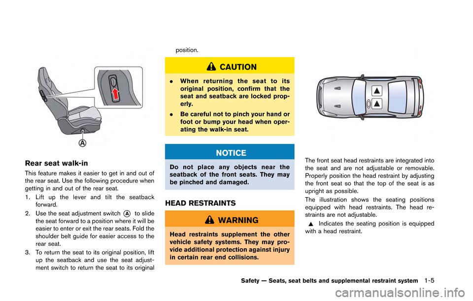
Rear seat walk-in
This feature makes it easier to get in and out of
the rear seat. Use the following procedure when
getting in and out of the rear seat.
1. Lift up the lever and tilt the seatbackforward.
2. Use the seat adjustment switch
*Ato slide
the seat forward to a position where it will be
easier to enter or exit the rear seats. Fold the
shoulder belt guide for easier access to the
rear seat.
3. To return the seat to its original position, lift up the seatback and use the seat adjust-
ment switch to return the seat to its original position.
CAUTION
.
When returning the seat to its
original position, confirm that the
seat and seatback are locked prop-
erly.
. Be careful not to pinch your hand or
foot or bump your head when oper-
ating the walk-in seat.
NOTICE
Do not place any objects near the
seatback of the front seats. They may
be pinched and damaged.
HEAD RESTRAINTS
WARNING
Head restraints supplement the other
vehicle safety systems. They may pro-
vide additional protection against injury
in certain rear end collisions.
The front seat head restraints are integrated into
the seat and are not adjustable or removable.
Properly position the head restraint by adjusting
the front seat so that the top of the seat is as
upright as possible.
The illustration shows the seating positions
equipped with head restraints. The head re-
straints are not adjustable.
Indicates the seating position is equipped
with a head restraint.
Safety — Seats, seat belts and supplemental restraint system1-5