2013 NISSAN GT-R park assist
[x] Cancel search: park assistPage 33 of 346
GTR-26GT-R Overview
For the first 3,000-6,000 miles (5,000-
10,000 km) of the vehicle’s service life,
and for the first 3,000-6,000 miles (5,000-
10,000 km) after a brake replacement, the
brake pad to brake rotor clearance is very
small. When parking, apply the parking
brake and move the shift lever to the
&Pposition. Idle the engine for more than 20
seconds without depressing the brake
pedal. This allows the brake pads to move
away from the rotor so the pad does not
contact the rotor.
Additionally, the brakes must be dry before
parking the vehicle after driving on wet roads
or after washing the vehicle. If the roads are
wet, lightly apply the brakes for a short
distance before parking the vehicle to dry
the brakes. After washing the vehicle, dry the
brakes by driving on a dry road for a few
miles and apply the brakes normally based
on traffic and road conditions.
The metallic brake pads and brake disc rotor
may rust together when the brakes are not
applied:
— If the vehicle is not idled for 20 secondswithout the brakes applied, or if the
brakes are applied when the vehicle is
shut off, the rotor and pads can rust
together, even when the brake pads are dry.
— If the brakes are wet when the vehicle is parked and the parking brake is applied
for a long time.
— The hill start assist system can apply the brakes even if the brake pedal is not
depressed. The brake pads and rotors
can rust together if the parking proce-
dure previously described is not fol-
lowed.
Contact a GT-R certified NISSAN dealer if
the brake pads and brake rotor have rusted
together.
NOTICE
To help reduce the possibility of the
rotors and brake pads rusting:
Have the brake pads and/or rotors
quenched when the brake pads are
replaced. For detailed information
about quenching, contact a GT-R certi-
fied NISSAN dealer.
After quenching the brake pads and/or
rotors, apply a brake of 0.5G to stop the
vehicle 6-7 times at least once a week
in a safe location. G-force can be
checked on the multi function display. Refer to the separate Multi Function
Display Owner’s Manual.
. To maintain steady braking performance in
both extremely high and low temperatures,
the gap between the brake pad and caliper
is larger than normal and large-size brake
pads are used. When driving over a bump, a
light rattling sound may be heard from the
brake pad. This does not indicate that there
is a malfunction.
. When the brake disc rotor undergoes
thermal expansion, a ticking noise may be
heard from the engaging portion of the
wheel and the brake disc rotor. This does
not indicate that there is a malfunction. The
noise will reduce when the temperature
decreases.
. In addition to noise resulting from uneven
tire wear discussed in the previous section,
the GT-R tires are more rigid than a typical
passenger car tire and are made from a
specially formulated rubber to maximize the
vehicle’s performance capabilities. These
characteristics cause the GT-R tires to have
more road noise than a typical passenger
car tire. This road noise is normal.
. Due to the performance capabilities and
Page 61 of 346
1-12Safety — Seats, seat belts and supplemental restraint system
SEAT BELT EXTENDERS
If, because of body size or driving position, it is
not possible to properly fit the lap-shoulder belt
and fasten it, an extender that is compatible with
the installed seat belts is available that can be
purchased. The extender adds approximately 8
in (200 mm) of length and may be used for either
the driver or front passenger seating position.
See a GT-R certified NISSAN dealer for
assistance with purchasing an extender if an
extender is required.
WARNING
.Only NISSAN seat belt extenders,
made by the same company which
made the original equipment seat
belts, should be used with the
NISSAN seat belts.
. Adults and children who can use the
standard seat belt should not use an
extender. Such unnecessary use
could result in serious personal
injury in the event of an accident.
. Never use seat belt extenders to
install child restraints. If the child
restraint is not secured properly, the
child could be seriously injured in a collision or a sudden stop.
SEAT BELT MAINTENANCE
.
To clean the seat belt webbing, apply a
mild soap solution or any solution recom-
mended for cleaning upholstery or carpets.
Then, wipe with a cloth and allow the seat
belts to dry in the shade. Do not allow the
seat belts to retract until they are completely
dry.
. If dirt builds up in the shoulder belt
guide of the seat belt anchors, the seat
belts may retract slowly. Wipe the shoulder
belt guide with a clean, dry cloth.
. Periodically check to see that the seat
belt and the metal components such as
buckles, tongues, retractors, flexible wires
and anchors work properly. If loose parts,
deterioration, cuts or other damage on the
webbing is found, the entire seat belt
assembly should be replaced.
WARNING
Do not allow children to play with the
seat belts. Most seating positions are
equipped with Automatic Locking Re-
tractor (ALR) mode seat belts. If the
seat belt becomes wrapped around a
child’s neck with the ALR mode acti-
vated, the child can be seriously injured
or killed if the seat belt retracts and
becomes tight. This can occur even if
the vehicle is parked. Unbuckle the seat
belt to release the child. If the seat belt
can not be unbuckled or is already
unbuckled, release the child by cutting
the seat belt with a suitable tool (such
as a knife or scissors) to release the
seat belt.
Children need adults to help protect them.
They need to be properly restrained.
In addition to the general information in this
manual, child safety information is available from
many other sources, including doctors, teachers,
government traffic safety offices, and community
organizations. Every child is different, so be sure
to learn the best way to transport your child.
There are three basic types of child restraint
CHILD SAFETY
Page 125 of 346
2-30Instruments and controls
NOTICE
While the warning light is illuminated,
the engine output is controlled so that
it does not increase.
Vehicle Dynamic Control (VDC)
warning light
The light will blink when the VDC system or the
traction control system is operating, thus alerting
the driver that the vehicle is nearing its traction
limits. The road surface may be slippery.
If the VDC warning light illuminates when the
VDC system is turned on, this light alerts the
driver to the fact that the VDC system’s fail-safe
mode is operating, for example the VDC or hill
start assist system may not be functioning
properly. Have the system checked by a GT-R
certified NISSAN dealer. If a malfunction occurs
in the system, the VDC system function will be
canceled but the vehicle is still driveable.
(
“Vehicle Dynamic Control (VDC) system”
page 5-49)
INDICATOR LIGHTS
Cruise main switch indicator
light
The light comes on when the cruise control is
pushed. The light turns off when the main switch
is pushed again. While the cruise control system
main switch indicator light is on, the cruise
control system is operational.
Cruise set switch indicator
light
The light comes on while the vehicle speed is
controlled by the cruise control system. If the
light blinks while the engine is running, it may
indicate the cruise control system is not
functioning properly. Have the system checked
by a GT-R certified NISSAN dealer.
Exterior light indicator
This indicator illuminates when the headlight
switch is turned to the AUTO,orposition and the front parking lights, instrument
panel lights, rear combination lights, license
plate lights or headlights are on. The indicator
turns off when these lights are turned off.
Front passenger air bag status
light
The front passenger air bag status light ()
will be lit and the passenger front air bag will be
OFF depending on how the front passenger
seat is being used. (
“NISSAN Advanced
Air Bag System (front seats)” page 1-37)
High beam indicator light
This light comes on when the headlight high
beam is on and goes out when the low beam is
selected.
Malfunction Indicator Light
(MIL)
If the malfunction indicator light comes on
steady or blinks while the engine is running, it
may indicate a potential emission control mal-
function.
The malfunction indicator light may also come on
steady if the fuel-filler cap is loose or missing, or
if the vehicle runs out of fuel. Check to make
sure the fuel-filler cap is installed and closed
tightly, and that the vehicle has at least 3 US
gallons (12 liters) of fuel in the fuel tank.
After a few driving trips, the
light should
turn off if no other potential emission control
system malfunction exists.
If this indicator light remains on for 20 seconds
Page 194 of 346
5 Starting and driving
Precautions when starting and driving ............................... 5-3Exhaust gas (carbon monoxide) ..................................... 5-3Three-way catalyst ............................................................. 5-3
Tire Pressure Monitoring System (TPMS) ................... 5-4
Avoiding collision and rollover ........................................ 5-7
Off-road recovery ............................................................... 5-7
Rapid air pressure loss ..................................................... 5-8
Drinking alcohol/drugs and driving ................................ 5-8All-Wheel Drive (AWD) driving safety precautions .... 5-9
Push-button ignition switch ................................................... 5-9
Operating range for engine start ................................ 5-10
Ignition switch operation ............................................... 5-10
Ignition switch positions ................................................ 5-10
Emergency engine shut off ........................................... 5-11
Intelligent Key battery discharge ................................. 5-11
Before starting the engine .................................................. 5-13
Starting the engine ............................................................... 5-13
Driving the vehicle ................................................................ 5-15 Dual clutch transmission ............................................... 5-15
Driving tips ........................................................................\
5-21
VDC, transmission and suspension setup switches .... 5-24 How to switch the modes ............................................ 5-25
Features of each mode .................................................. 5-27 Turbocharger system ........................................................... 5-31
R mode start function ......................................................... 5-32
How to use R mode start function ........................... 5-33
Parking brake ........................................................................\
. 5-33
Cruise control ........................................................................\
5-34 Precautions on cruise control .................................... 5-35
Steering-wheel-mounted controls ............................ 5-35
Indicators and display .................................................. 5-36
Cruise control operations ........................................... 5-36
Hill Start Assist ..................................................................... 5-38
Break-in schedule ................................................................ 5-39 Wheel alignment ........................................................... 5-39
Increasing fuel economy ..................................................... 5-40
All-Wheel Drive (AWD) ...................................................... 5-41 AWD warning light ....................................................... 5-41
Tight corner braking phenomenon ........................... 5-42
Tires ........................................................................\
.......... 5-43AWD system characteristics ...................................... 5-43
Limited Slip Differential (LSD) .......................................... 5-44
Parking/parking on hills ....................................................... 5-45
Power steering ...................................................................... 5-46
Brake system ........................................................................\
. 5-47 Braking precautions ..................................................... 5-47
Parking brake break-in ................................................. 5-47
Page 214 of 346
.Fifth gear:
Use this position for all normal forward
driving at highway speeds. Engine braking
is weaker in this position.
. Sixth gear:
Use this position for all normal forward
driving at highway speeds. Engine braking
is weakest in this position.
Suggested maximum speed in each gear:
Downshift to a lower gear if the engine is not
running smoothly, or if you need to accelerate.
Do not exceed the maximum suggested speed
(shown below) in any gear. For level road
driving, use the highest gear suggested for that
speed. Always observe posted speed limits, and
drive according to the road conditions that will
ensure safe operation. Do not over-rev the
engine when shifting to a lower gear as it may
cause engine damage or loss of vehicle control.
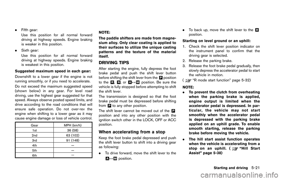
Gear MPH (km/h)
1st 36 (58)
2nd 63 (102)
3rd 91 (148)
4th —
5th —
6th —
NOTE:
The paddle shifters are made from magne-
sium alloy. Only clear coating is applied to
their surfaces to utilize the unique casting
patterns and the texture of the material
itself.
DRIVING TIPS
After starting the engine, fully depress the foot
brake pedal and push the shift lever button
before shifting the shift lever from the
&Pposition
to the&R,&N,or&A↔&Mposition. Be sure the
vehicle is fully stopped before attempting to shift
the shift lever.
The transmission is designed so that the foot
brake pedal must be depressed before shifting
from
&Pto any other position.
The shift lever cannot be moved out of the
&Pposition and into any other position with the
ignition switch other in the LOCK, OFF or ACC
position.
When accelerating from a stop
Keep the foot brake pedal depressed and push
the shift lever button to shift into a driving gear
as following:
. To drive forward, move the shift lever to the
&A↔&Mposition. .
To back up, move the shift lever to the
&Rposition.
Starting on level ground or an uphill:
1. Check the shift lever position indicator on the instrument panel to confirm that the
driving gear is selected.
2. Release the parking brake.
3. Release the foot brake pedal gradually, then slowly depress the accelerator pedal to start
the vehicle in motion.
(
“R mode start function” page 5-32)
NOTE:
. To prevent the clutch from overheating
when the parking brake is applied,
engine output is limited when the
accelerator pedal is depressed. In par-
ticular, the vehicle may not start
smoothly when the accelerator pedal
is depressed with the parking brake
applied on an uphill grade. To enable
smooth starting, release the parking
brake before moving the vehicle.
. The hill start assist function operates
when the vehicle is accelerating from a
stop on an uphill. (
“Hill Start
Assist” page 5-38)
Starting and driving5-21
Page 239 of 346
5-46Starting and driving
.HEADED UPHILL OR DOWNHILL, NO
CURB:
*3Turn the wheels toward the side of the
road so the vehicle will move away from
the center of the road if it moves.
4. Push the ignition switch to the LOCK position.
The GT-R uses brake pad materials that have
high metallic content. The brake pad material
helps maintain braking performance in a wide
range of weather and driving conditions.
For the first 3,000 - 6,000 miles (5,000 -
10,000 km) of the vehicle’s service life, and for
the first 3,000 - 6,000 miles (5,000 - 10,000
km) after a brake replacement, the brake pad to
brake rotor clearance is very small. When
parking, apply the parking brake and move the
shift lever to the
&Pposition. Idle the engine for
more than 20 seconds without depressing the
brake pedal. This allows the brake pads to move
away from the rotor so the pad does not contact
the rotor.
Additionally, the brakes must be dry before
parking the vehicle after driving on wet roads or
after washing the vehicle. If the roads are wet,
lightly apply the brakes for a short distance
before parking the vehicle to dry the brakes.
After washing the vehicle, dry the brakes by
driving on a dry road for a few miles and apply the brakes normally based on traffic and road
conditions.
The metallic brake pads and brake disc rotor
may rust together when the brakes are not
applied:
.
If the vehicle is not idled for 20 seconds
without the brakes applied, or if the brakes
are applied when the vehicle is shut off, the
rotor and pads can rust together, even when
the brake pads are dry.
. If the brakes are wet when the vehicle is
parked and the parking brake is applied for a
long time.
Contact a GT-R certified NISSAN dealer if the
brake pads and brake rotor have rusted
together.
WARNING
If the engine is not running or is turned
off while driving, the power assist for
the steering will not work. Steering will
be harder to operate.
The power assisted steering uses a hydraulic
pump, driven by the engine, to assist steering.
If the engine stops or the drive belt breaks, you
will still have control of the vehicle. However,
much greater steering effort is needed, espe-
cially in sharp turns and at low speeds.
POWER STEERING
Page 240 of 346
BRAKING PRECAUTIONS
The brake system has two separate hydraulic
circuits. If one circuit malfunctions, you will still
have braking at two wheels.
You may feel a small click and hear a sound
when the brake pedal is fully depressed slowly.
This is not a malfunction and indicates that the
brake assist mechanism is operating properly.
Vacuum assisted brakes
The brake booster aids braking by using engine
vacuum. If the engine stops, you can stop the
vehicle by depressing the brake pedal. However,
greater foot pressure on the brake pedal will be
required to stop the vehicle and the stopping
distance will be longer.
Wet brakes
When the vehicle is washed or driven through
water, the brakes may get wet. As a result, your
braking distance will be longer and the vehicle
may pull to one side during braking.
To dry brakes, drive the vehicle at a safe speed
while lightly tapping the brake pedal to heat-up
the brakes. Do this until the brakes return to
normal. Avoid driving the vehicle at high speeds
until the brakes function correctly.
Using the brakes
Avoid resting your foot on the brake pedal while
driving. This will cause overheating of the
brakes, wearing out the brake and pads faster
and reduce gas mileage.
To help reduce brake wear and to prevent the
brakes from overheating, reduce speed and
downshift to a lower gear before going down a
slope or long grade. Overheated brakes may
reduce braking performance and could result in
loss of vehicle control.
WARNING
.While driving on a slippery surface,
be careful when braking, accelerat-
ing or downshifting. Abrupt braking
or accelerating could cause the
wheels to skid and result in an
accident.
. If the engine is not running or is
turned off while driving, the power
assist for the brakes will not work.
Braking will be harder.
PARKING BRAKE BREAK-IN
Break in the parking brake shoes whenever the
stopping effect of the parking brake is weakened
or whenever the parking brake shoes and/or
drums/rotors are replaced, in order to assure the
best braking performance.
This procedure is described in the vehicle
service manual and can be performed by a
GT-R certified NISSAN dealer.
Starting and driving5-47
BRAKE SYSTEM
Page 251 of 346
6-4In case of emergency
NOTICE
.Never install tire chains on a punc-
tured run-flat tire, as this could
damage your vehicle.
. Avoid driving over any projection or
pothole, as the clearance between
the vehicle and the ground is smal-
ler than normal.
. Do not enter an automated car wash
with a punctured run-flat tire.
. Have the punctured tire replaced by
your GT-R certified NISSAN dealer
as soon as possible, as the tire’s
performance capability is reduced.
If you have a flat tire and have to stop the
vehicle, follow the instructions below.
1. Safely move the vehicle off the road and away from traffic.
2. Turn on the hazard warning flashers.
3. Park on a level surface and apply the parking brake. Move the shift lever to the
&Pposition.
4. Turn off the engine.
5. Raise the hood to warn other traffic, and to signal professional road assistance person-
nel that you need assistance. 6. Have all passengers get out of the vehicle
and stand in a safe place, away from traffic
and clear of the vehicle.
If needed Roadside Assistance is available.
Please see your Warranty Information Booklet
for the toll-free number to call (U.S.) or Warranty
Information Booklet (Canada).
For the tire removing procedure, see the
following section. (
“Jacking vehicle and
removing wheels” page 8-42)
The following circumstances indicate that the
battery is discharged.
. The starter motor does not turn or it turns
weakly and the engine does not start.
. The vehicle lights are much dimmer than
usual.
. The sound of the horn is weak. The horn
makes no sound.
NOTICE
When the battery is discharged, do not
close either of the front doors. The
automatic window adjusting function
will not work, and the side roof panel
may be damaged.
To start your engine with a booster battery, the
instructions and precautions below must be
followed.
For the battery maintenance information, see the
following section. (
“Battery” page 8-17)
JUMP STARTING