Page 4 of 602
Overview
Drive mode-selector (if so equipped)
P. 3 - 8 4Center vents P.5-2
Gearshift or selector lever P.3-71, 3-75 12V power outlet P.3-238 Glove compartment P.3-247
Fuel tank filler door
release lever P.1-4 Rear window defogger switch P.3-203Side vents P.5-2
Engine hood release lever
P.7-4 Hazard warning flasher switch P.3-193
Mitsubishi Multi-Communication System
(if so equipped)
Audio (if so equipped) P.5-46
Clock (if so equipped) P.5-103
Air conditioning P.5-6, 5-16, 5-25, 5-35 Key slot (if so equipped) P.3-28
Cup holder P.3-251
Fuses P.7-39
Multi-information meter switch
P.3-131
Parking brake lever P.7-33
BK0150700US.book 2 ページ 2012年3月22日 木曜日 午後6時46分
Page 25 of 602

1-8 General information
1
Important point!Due to the large number of accessory and replacement parts
provided by different manufacturers in the market, it is not
always possible for an authorized Mitsubishi Motors dealer to
check whether the attachment or installation of non-Mitsubishi
Motors genuine parts affects the driving safety of your
Mitsubishi-vehicle.
Modification/alterations to the electrical or fuel
systems
N00301800138
Mitsubishi Motors manufactures high quality vehicles with an
emphasis on safety. It is important to consult an authorized
Mitsubishi Motors dealer before installation of any accessory
which may involve modification of the electrical or fuel sys-
tems.
WARNING
!�While driving, do not use a cellular phone in a way
that hinders safe driving. Anything, including cellu-
lar phone usage, that distracts you from the safe
operation of your vehicle increases your risk of an
accident.
Refer to and follow all state and local laws in your
area regarding cellular phone usage while driving.
CAUTION
!� Please consult an authorized Mitsubishi Motors
dealer concerning any such accessory fitment or
modification.
If the wires interfere with the vehicle body or
improper installation methods are used (protective
fuses not included, etc.), electronic devices may be
adversely affected, resulting in a fire, vehicle dam-
age, or other accident.
BK0150700US.book 8 ページ 2012年3月22日 木曜日 午後6時46分
Page 502 of 602

7
Vehicle care and maintenance
Service precautions . . . . . . . . . . . . . . . . . . . . . . . .7- 2
Catalytic converter . . . . . . . . . . . . . . . . . . . . . . . . .7- 3
Engine hood . . . . . . . . . . . . . . . . . . . . . . . . . . . . . .7- 4
View of the engine compartment . . . . . . . . . . . . . .7- 6
Engine oil and oil filter . . . . . . . . . . . . . . . . . . . . .7- 7
Engine coolant . . . . . . . . . . . . . . . . . . . . . . . . . . . .7- 10
Air cleaner filter . . . . . . . . . . . . . . . . . . . . . . . . . . .7- 12
Manual transaxle oil (if so equipped) . . . . . . . . . .7- 17
Continuously variable transmission (CVT) fluid (if so equipped) . . . . . . . . . . . . . . . . . . . . . . . . . .7- 18
Transfer oil (All-wheel drive models) . . . . . . . . . .7- 18
Rear axle oil (All-wheel drive models) . . . . . . . . .7- 19
Washer fluid . . . . . . . . . . . . . . . . . . . . . . . . . . . . . .7- 19
Brake fluid/Clutch fluid (if so equipped) . . . . . . . .7- 20
Battery . . . . . . . . . . . . . . . . . . . . . . . . . . . . . . . . . .7- 21
Tires . . . . . . . . . . . . . . . . . . . . . . . . . . . . . . . . . . . .7- 23
Clutch pedal free play (if so equipped) . . . . . . . . .7- 32
Brake pedal free play . . . . . . . . . . . . . . . . . . . . . . .7- 33
Parking brake . . . . . . . . . . . . . . . . . . . . . . . . . . . . .7- 33
Wiper blades . . . . . . . . . . . . . . . . . . . . . . . . . . . . .7- 34
Emission-control system maintenance. . . . . . . . . .7- 34 General maintenance . . . . . . . . . . . . . . . . . . . . . . . 7- 36
For cold and snowy weather . . . . . . . . . . . . . . . . . 7- 38
Fusible links . . . . . . . . . . . . . . . . . . . . . . . . . . . . . 7- 39
Fuses . . . . . . . . . . . . . . . . . . . . . . . . . . . . . . . . . . . 7- 39
Replacement of light bulbs . . . . . . . . . . . . . . . . . . 7- 47
Vehicle care precautions . . . . . . . . . . . . . . . . . . . . 7- 69
Cleaning the inside of your vehicle . . . . . . . . . . . . 7- 70
Cleaning the outside of your vehicle . . . . . . . . . . . 7- 71
BK0150700US.book 1
ページ 2012年3月22日 木曜日 午後6時46分
Page 540 of 602

Vehicle care and maintenance7-39
7
Fusible links
N00942700305
The fusible links will melt to prevent a fire if a large current
attempts to flow through certain electrical systems.
In case of a melted fusible link, see your authorized Mitsubishi
Motors dealer or a repair facility of your choice for inspection
and replacement.
For the fusible links, please refer to “Fuse load capacities” on
page 7-41.
Fuses
N00942800856
Fuse block locationTo prevent damage to the electrical system from short-circuit-
ing or overloading, each individual circuit is equipped with a
fuse. The fuse blocks are located in the passenger compartment
and in the engine compartment.Passenger compartmentThe fuse blocks in the passenger compartment are located
behind the fuse lid.
WARNING
!�
Fusible links must not be replaced by any other
device. Failing to fit the correct fusible link may
result in fire in the vehicle, property destruction and
serious or fatal injuries at any time.
A- Main fuse block
B- Sub fuse block
BK0150700US.book 39 ページ 2012年3月22日 木曜日 午後6時46分
Page 542 of 602
Vehicle care and maintenance7-41
7
Engine compartmentIn the engine compartment, the fuse block is located as shown
in the illustration.Fuse load capacities
N00954800172
This fuse list shows the names of the electrical systems and
their fuse capacities.
There are spare fuses in the fuse block cover in the engine
compartment. Always replace a blown fuse with one of the
same capacity as the original.
Passenger compartment fuse location table
1- Push the lock lever.
2- Remove the fuse block cover.
Passenger compartment fuse location Sub fuse block
Main fuse block
BK0150700US.book 41 ページ
2012年3月22日 木曜日 午後6時46分
Page 543 of 602
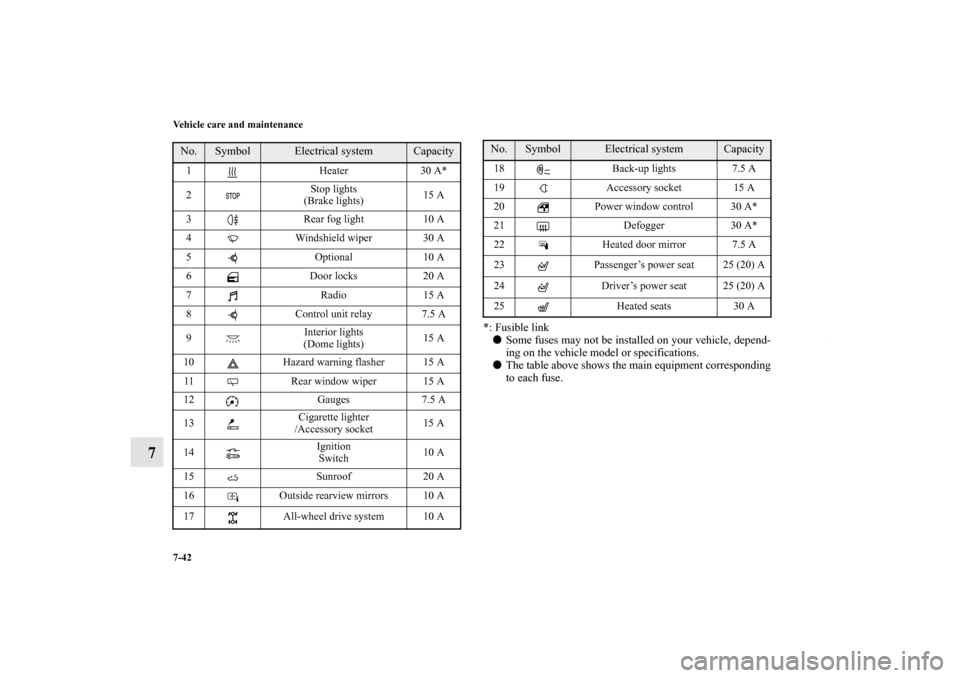
7-42 Vehicle care and maintenance
7
*: Fusible link� Some fuses may not be installed on your vehicle, depend-
ing on the vehicle model or specifications.
� The table above shows the main equipment corresponding
to each fuse.
No.
Symbol
Electrical system
Capacity
1 Heater30 A*
2 Stop lights
(Brake lights) 15 A
3 Rear fog light 10 A
4 Windshield wiper 30 A
5 Optional10 A
6 Door locks20 A
7 Radio15 A
8 Control unit relay 7.5 A
9 Interior lights
(Dome lights) 15 A
10 Hazard warning flasher 15 A
11 Rear window wiper 15 A
12 Gauges7.5 A
13 Cigarette lighter
/Accessory socket 15 A
14 Ignition
Switch 10 A
15 Sunroof20 A
16 Outside rearview mirrors 10 A
17 All-wheel drive system 10 A
18 Back-up lights 7.5 A
19 Accessory socket 15 A
20 Power window control 30 A*
21 Defogger30 A*
22 Heated door mirror 7.5 A
23 Passenger’s power seat 25 (20) A
24 Driver’s power seat 25 (20) A
25 Heated seats30 ANo.
Symbol
Electrical system
Capacity
BK0150700US.book 42 ページ 2012年3月22日 木曜日 午後6時46分
Page 545 of 602

7-44 Vehicle care and maintenance
7
*: Fusible link� Some fuses may not be installed on your vehicle, depend-
ing on the vehicle model or specifications.
� The table above shows the main equipment corresponding
to each fuse.
There are no 7.5 A, 25 A or 30 A spare fuses. If a fuse of one of
these capacities blows, replace it temporarily by borrowing one
of the fuses indicated below.
7.5 A: 10 A spare fuse
25 A: 20 A spare fuse
30 A: 30 A audio amplifier fuse
Replace the borrowed fuse with a fuse that has the correct
capacity as soon as possible.
17 Headlight
(low beam) (right) Discharge 20 A
18 Headlight
(low beam) (left) Halogen 10 A
19 Headlight
(low beam) (right) Halogen 10 A
20 ENG/POWER 10 A
21 Ignition coil 10 A
22 ENG/POWER 20 A
Fuel line heater 25 A
23 Fuel pump 15 A
24 Starter 30 A*
25 — — —
26 Anti-lock braking system 40 A*
27 Anti-lock braking system 30 A*
28 Air conditioning condenser fan
motor 30 A*
29 Radiator fan 40 A*
30 IOD IOD 30 A
31 Audio amplifier 30 ANo.
Symbol
Electrical system
Capacity
32 Diesel30 A
33 — Spare fuse10 A
34 — Spare fuse15 A
35 — Spare fuse20 ANo.
Symbol
Electrical system
Capacity
BK0150700US.book 44 ページ 2012年3月22日 木曜日 午後6時46分
Page 547 of 602
7-46 Vehicle care and maintenance
7
3. Clamp it on the fuse you wish to remove, and pull the fusestraight out from the fuse block. 4. Use the fuse location diagrams and the matching tables, to
check the fuse that is related to the problem. If the fuse is
not blown, something else must be causing the problem.
Have the system inspected by your authorized Mitsubishi
Motors dealer or a repair facility of your choice.
B- Fuse is OK
C- Blown fuse
BK0150700US.book 46 ページ 2012年3月22日 木曜日 午後6時46分

P. 3 - 8 4Center vents P.5-2
Gearshift or selector lever P.3-71, 3-75 12V power outlet P.3-238 Glove compartment P.3-247
Fuel tank filler door
release l")