Page 554 of 706
Comfort controls
5-141
5 Antenna
N00734200468
To removeTurn the pole (A) counterclockwise.To installScrew the pole (A) clockwise into the base (B) until it is
securely retained.NOTE�Be sure to remove the roof antenna in the following cases:
• When using an automatic car wash
• When covering your vehicle with a car cover
• When driving into a structure that has a low ceiling
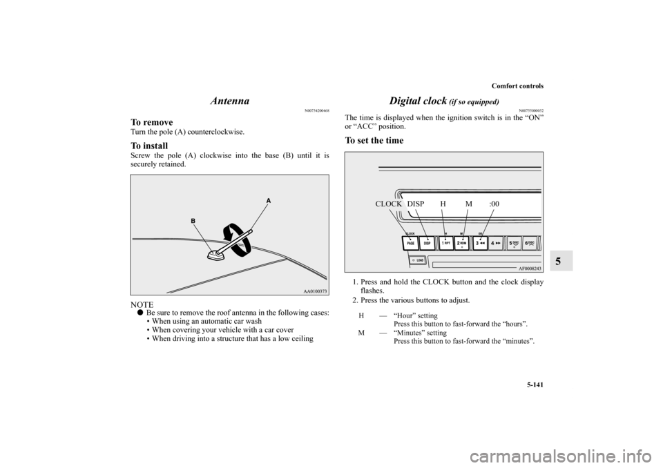
Digital clock
(if so equipped)
N00755000052
The time is displayed when the ignition switch is in the “ON”
or “ACC” position.To set the time1. Press and hold the CLOCK button and the clock display
flashes.
2. Press the various buttons to adjust.H — “Hour” setting
Press this button to fast-forward the “hours”.
M — “Minutes” setting
Press this button to fast-forward the “minutes”.
CLOCK DISP H M :00
BK0151000US.book 141 ページ 2012年3月29日 木曜日 午後6時8分
Page 555 of 706

5-142 Comfort controls
5
3. When the time is set, press the DISP button to stop the
clock display from flashing. After time signal setting,
however, the clock display automatically stops flashing.NOTE�Reset the time after the battery terminals are disconnected
and reconnected.
�Seconds do not appear in the clock display, but after
adjusting the “Minutes” setting and time signal setting,
the clock begins to operate from 0 seconds.
General information about your radio
N00733900396
Your vehicle’s radio receives both AM and FM stations.
The quality of your reception is affected by distance, obstacles,
and signal interference.
This radio complies with Part 15 of Federal Communications
Commission (FCC) Rules (for vehicles sold in U.S.A.). Opera-
tion is subject to the following conditions:
�The device may not cause harmful interference.
�This device must accept any interference recieved, includ-
ing interference that may cause undesirable operation.
:00 — Time signal setting
At the same time the button is pressed, the fol-
lowing modifications are made.
10:00 - 10:29 ......Change to 10:00
10:30 - 10:59 ......Change to 11:00
CAUTION
!�Changes or modifications not expressly approved by
the party meeting the above conditions could void
the user’s authority to operate the equipment.
BK0151000US.book 142 ページ 2012年3月29日 木曜日 午後6時8分
Page 563 of 706

6-6 For emergencies
6
5. If you do not see steam or spray coming from under the
hood, leave the engine on until the bar graph for the
engine coolant temperature warning display on the multi-
information display goes down. When it is in the middle
of the normal zone, you can start driving again. If the bar
graph stays in the red zone, turn off the engine.
6. When you do not see any more steam or spray, open the
hood. Look for obvious leaks, such as a split radiator
hose. Be careful as components will be hot. Any leak
source must be repaired.
7. If there is no obvious leak source, check the coolant level
in the reserve tank. If there is none, or if it is too low,
slowly add coolant.8. If the reserve tank needs coolant, you will probably also
need to add coolant to the radiator. Do not loosen or
remove the radiator cap until the engine has cooled down.
9. Start the engine, and slowly add coolant, up to the bottom
of the filler neck. Use plain water if you have to (and
replace it with the right coolant as soon as possible).
10. Replace the radiator cap and tighten it fully. Check the
engine coolant temperature display on the multi-informa-
tion display. You can start driving again when the bar
graph for the engine coolant temperature display returns
to the normal zone.
11. Have your vehicle checked by your authorized Mitsubishi
Motors dealer or a repair facility of your choice.
WA R N I N G
!�Before raising the engine hood, check to see if there
is steam or spray coming from under the hood.
Steam or spray coming from an overheated engine
could seriously scald you.
Do not open the hood until there is no steam or
spray.
WA R N I N G
!�Removing the radiator cap could scald you with
escaping hot water or steam. When checking the
radiator level, cover the cap with a cloth before try-
ing to remove it. Turn it slowly counterclockwise,
without pressing down, to the first notch. The pres-
sure in the system will then be let out. When the
pressure is COMPLETELY LET OUT, press down
and keep turning the cap counterclockwise until it
will come off.
BK0151000US.book 6 ページ 2012年3月29日 木曜日 午後6時8分
Page 568 of 706
For emergencies
6-11
6
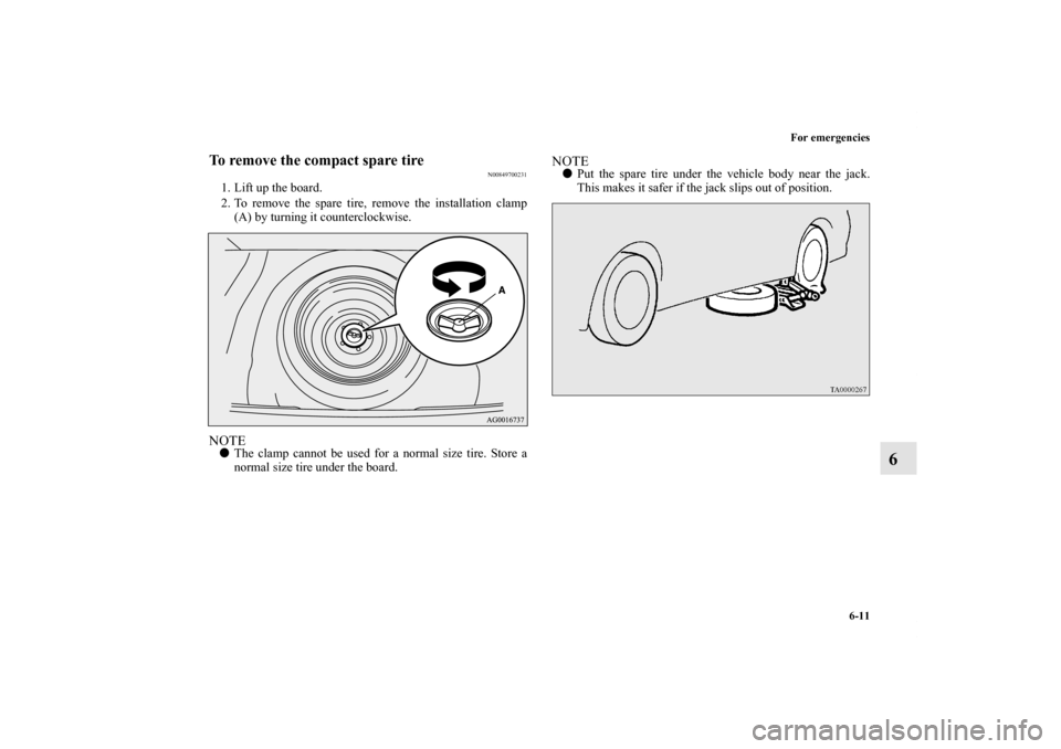
To remove the compact spare tire
N00849700231
1. Lift up the board.
2. To remove the spare tire, remove the installation clamp
(A) by turning it counterclockwise.NOTE�The clamp cannot be used for a normal size tire. Store a
normal size tire under the board.
NOTE�Put the spare tire under the vehicle body near the jack.
This makes it safer if the jack slips out of position.
BK0151000US.book 11 ページ 2012年3月29日 木曜日 午後6時8分
Page 574 of 706
For emergencies
6-17
6
8. Lower the vehicle slowly by rotating the wheel nut
wrench counterclockwise until the tire touches the
ground.9. Tighten the nuts in the order shown in the illustration until
each nut has been tightened to the torque listed here.
65 to 80 ft-lb (88 to 108 N•m)
10. Lower the jack all the way and remove it.
CAUTION
!�Never use your foot or a pipe extension to apply
added force to the wheel nut wrench when tighten-
ing the wheel nuts. If you do so, you can over-tighten
the wheel nuts and damage the wheel, wheel nuts
and hub bolts.
BK0151000US.book 17 ページ 2012年3月29日 木曜日 午後6時8分
Page 605 of 706
7-24 Vehicle care and maintenance
7
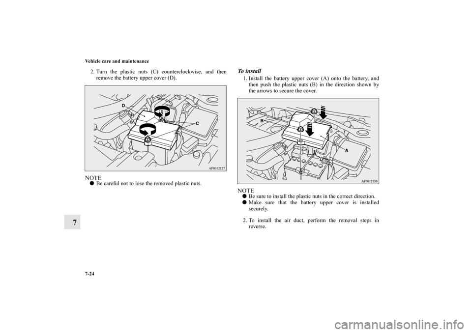
2. Turn the plastic nuts (C) counterclockwise, and then
remove the battery upper cover (D).NOTE�Be careful not to lose the removed plastic nuts.
To i n s t a l l1. Install the battery upper cover (A) onto the battery, and
then push the plastic nuts (B) in the direction shown by
the arrows to secure the cover.NOTE�Be sure to install the plastic nuts in the correct direction.
�Make sure that the battery upper cover is installed
securely.
2. To install the air duct, perform the removal steps in
reverse.
BK0151000US.book 24 ページ 2012年3月29日 木曜日 午後6時8分
Page 642 of 706
Vehicle care and maintenance
7-61
7
3. Turn the bulb (C) counterclockwise, and then remove the
headlight bulb with holder.4. While holding down the tab (D), pull out the bulb (E).
5. To install the bulb, perform the removal steps in reverse.*- Front of the vehicle
BK0151000US.book 61 ページ 2012年3月29日 木曜日 午後6時8分
Page 644 of 706
Vehicle care and maintenance
7-63
7
2. Turn the cap (B) counterclockwise to remove it. 3. Turn the bulb (C) counterclockwise to remove it.*- Front of the vehicle
*- Front of the vehicle
BK0151000US.book 63 ページ 2012年3月29日 木曜日 午後6時8分

 counterclockwise, and then remove the
headlight bulb with holder.4. While holding down the tab (D), pull out the bulb (E).
5. To install the bu")
 counterclockwise to remove it. 3. Turn the bulb (C) counterclockwise to remove it.*- Front of the vehicle
*- Front of the vehicle
BK0151000US.bo")