2013 MITSUBISHI iMiEV heating
[x] Cancel search: heatingPage 146 of 258

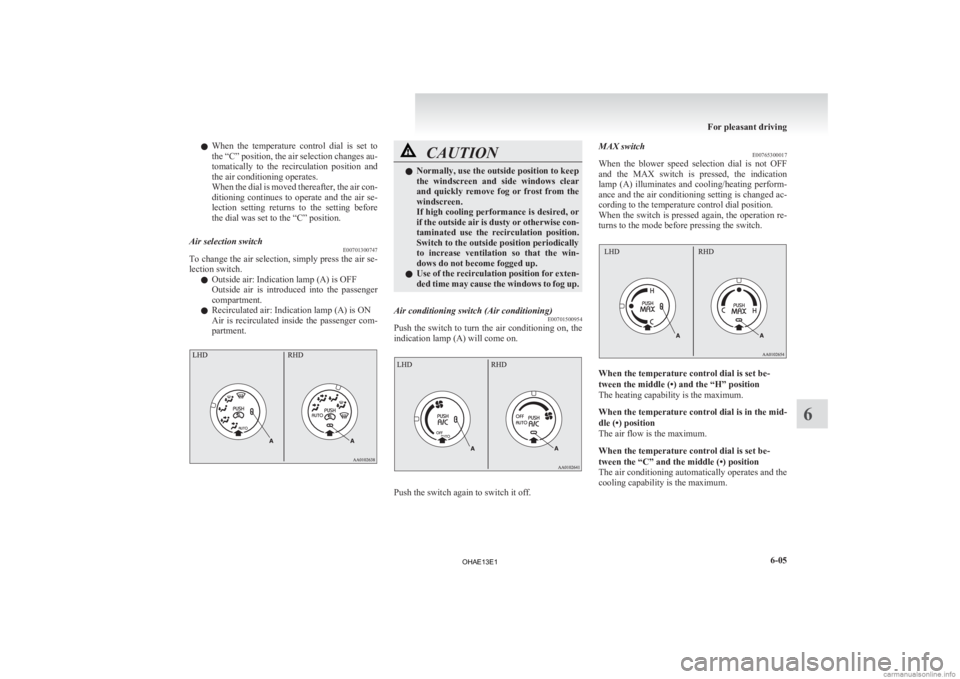
Control panel
E00700600567A- Temperature control dial
B- MAX switch
C- Blower speed selection dial
D- Air conditioning switch E- Mode selection dialF- Air selection switch
NOTE l There is an interior air temperature sensor
(G) in the illustrated position.
Never place anything over the sensor, since
doing so will prevent it from functioning prop-
erly. Blower speed selection dial
E00700700281
Select the blower speed by turning the blower
speed selection dial clockwise or anticlockwise.
Turn
the dial clockwise to increase the air flow and
anticlockwise to decrease the air flow.
When the dial is set to the “AUTO” position, the
air flow is adjusted automatically according to the
temperature of the interior and the position of the
temperature control dial. Temperature control dial
E00700900401
Turn the temperature control dial clockwise or anti-
clockwise.
When
the dial is set to the middle (•) position, only
uncooled and unheated air will flow.
When the dial is moved to the middle (•) position
when using cooling or heating, the cooling or heat-
ing stops. NOTE
l When
the dial is moved from the middle (•)
position to the left while the air conditioning
is not operating, the air temperature will not
change.
l When the dial is moved to the middle (•) po-
sition and then to the left while the air condi-
tioning is operating, the air conditioning is op-
erated again. For pleasant driving
6-04
6
OHAE13E1
Page 147 of 258

l
When the temperature control dial is set to
the “C” position, the air selection changes au-
tomatically to the recirculation position and
the air conditioning operates.
When the dial is moved thereafter, the air con-
ditioning continues to operate and the air se-
lection setting returns to the setting before
the dial was set to the “C” position.
Air selection switch E00701300747
To change the air selection, simply press the air se-
lection switch.
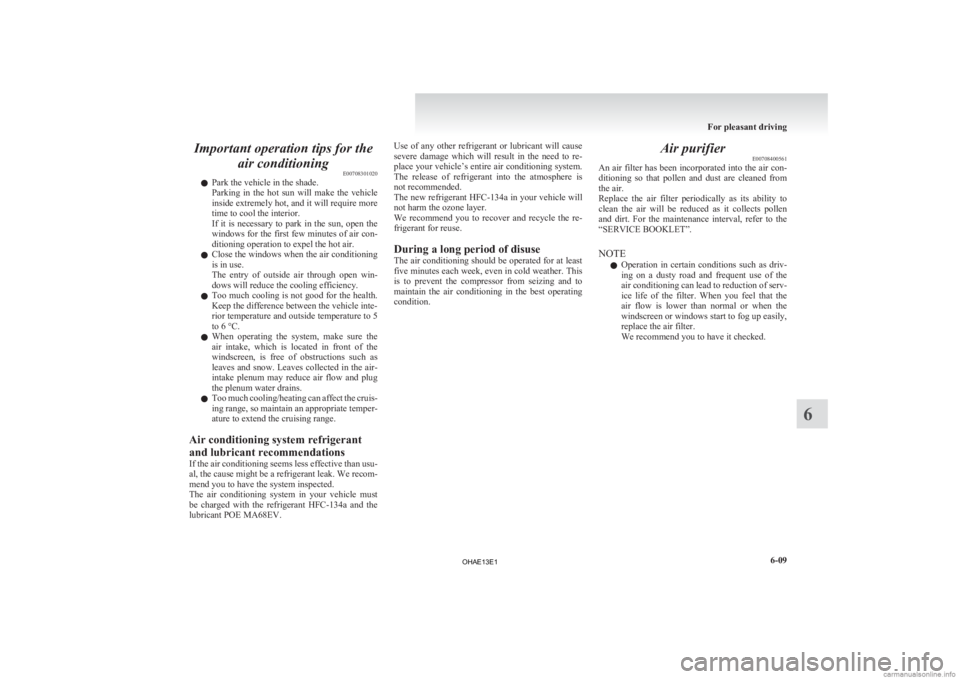
l Outside air: Indication lamp (A) is OFF
Outside
air is introduced into the passenger
compartment.
l Recirculated air: Indication lamp (A) is ON
Air is recirculated inside the passenger com-
partment. CAUTION
l
Normally, use the outside position to keep
the
windscreen and side windows clear
and quickly remove fog or frost from the
windscreen.
If high cooling performance is desired, or
if the outside air is dusty or otherwise con-
taminated use the recirculation position.
Switch to the outside position periodically
to increase ventilation so that the win-
dows do not become fogged up.
l Use of the recirculation position for exten-
ded time may cause the windows to fog up.
Air conditioning switch (Air conditioning) E00701500954
Push the switch to turn the air conditioning on, the
indication lamp (A) will come on. Push the switch again to switch it off.MAX switch
E00765300017
When
the blower speed selection dial is not OFF
and the MAX switch is pressed, the indication
lamp (A) illuminates and cooling/heating perform-
ance and the air conditioning setting is changed ac-
cording to the temperature control dial position.
When the switch is pressed again, the operation re-
turns to the mode before pressing the switch. When the temperature control dial is set be-
tween the middle (•) and the “H” position
The heating capability is the maximum.
When
the temperature control dial is in the mid-
dle (•) position
The air flow is the maximum.
When the temperature control dial is set be-
tween the “C” and the middle (•) position
The air conditioning automatically operates and the
cooling capability is the maximum. For pleasant driving
6-05 6
OHAE13E1
Page 148 of 258

NOTE
l When
the blower speed selection dial or tem-
perature control dial is operated with the indi-
cation lamp illuminated, the indication lamp
goes out and the selected function overrides
others.
Other functions return to the mode before
pressing the MAX switch.
l When the air conditioning is operated with
the MAX switch, the air conditioning does
not stop if the function is cancelled.
l Do not use the cooling/heating function with
the MAX switch for a long time. Since the
power consumption is larger than cooling/
heating not using the MAX switch, the cruis-
ing range is shortened.
Operating the air conditioning system E00701800465
Heating 1.Set
the mode selection dial to the “ ”
posi-
tion
2. Set the selection switch (A) to the outside po- sition.
3. Turn the temperature control dial clockwise or anticlockwise to the desired temperature
between the middle (•) and “H” position. 4. Select the desired blower speed.
NOTE
l When
the blower speed selection dial is set
to the “AUTO” position, the air flow is adjus-
ted automatically according to the tempera-
ture of the interior and the position of the tem-
perature control dial. Quick heating
1.Set
the mode selection dial to the “ ”
posi-
tion. 2. Set
the air selection switch (A) to the outside
position.
3. Turn the temperature control dial clockwise or anticlockwise between the middle (•) posi-
tion and “H” position.
4. Turn the blower speed selection dial to any position other than “OFF” position.
5. Press the MAX switch (B). NOTE
l Do
not use the heating function with the
MAX switch for a long time. Since the pow-
er consumption is larger than heating not us-
ing the MAX switch, the cruising range is
shortened. For pleasant driving
6-06
6 LHDRHD
OHAE13E1
Page 151 of 258

Important operation tips for the
air conditioning E00708301020
l Park the vehicle in the shade.
Parking
in the hot sun will make the vehicle
inside extremely hot, and it will require more
time to cool the interior.
If it is necessary to park in the sun, open the
windows for the first few minutes of air con-
ditioning operation to expel the hot air.
l Close the windows when the air conditioning
is in use.
The entry of outside air through open win-
dows will reduce the cooling efficiency.
l Too much cooling is not good for the health.
Keep the difference between the vehicle inte-
rior temperature and outside temperature to 5
to 6 °C.
l When operating the system, make sure the
air intake, which is located in front of the
windscreen, is free of obstructions such as
leaves and snow. Leaves collected in the air-
intake plenum may reduce air flow and plug
the plenum water drains.
l Too much cooling/heating can affect the cruis-
ing range, so maintain an appropriate temper-
ature to extend the cruising range.
Air conditioning system refrigerant
and lubricant recommendations
If the air conditioning seems less effective than usu-
al, the cause might be a refrigerant leak. We recom-
mend you to have the system inspected.
The air conditioning system in your vehicle must
be charged with the refrigerant HFC-134a and the
lubricant POE MA68EV. Use of any other refrigerant or lubricant will cause
severe
damage which will result in the need to re-
place your vehicle’s entire air conditioning system.
The release of refrigerant into the atmosphere is
not recommended.
The new refrigerant HFC-134a in your vehicle will
not harm the ozone layer.
We recommend you to recover and recycle the re-
frigerant for reuse.
During a long period of disuse
The air conditioning should be operated for at least
five minutes each week, even in cold weather. This
is to prevent the compressor from seizing and to
maintain the air conditioning in the best operating
condition. Air purifier
E00708400561
An
air filter has been incorporated into the air con-
ditioning so that pollen and dust are cleaned from
the air.
Replace the air filter periodically as its ability to
clean the air will be reduced as it collects pollen
and dirt. For the maintenance interval, refer to the
“SERVICE BOOKLET”.
NOTE
l Operation in certain conditions such as driv-
ing on a dusty road and frequent use of the
air conditioning can lead to reduction of serv-
ice life of the filter. When you feel that the
air flow is lower than normal or when the
windscreen or windows start to fog up easily,
replace the air filter.
We recommend you to have it checked. For pleasant driving
6-09 6
OHAE13E1
Page 187 of 258

WARNING
l If electrolyte fluid is not visible, or ap-
pears to be frozen, Do Not Attempt Jump
Starting!
A battery might rupture or explode if the
temperature is below the freezing point
or if it is not filled to the proper level.
7. Connect
one end of one jumper cable to the positive (+) terminal of the discharged bat-
tery (A), and the other end to the positive (+)
terminal of the booster battery (B).
Connect one end of the other jumper cable to
the negative (-) terminal of the booster bat-
tery, and the other end to the designated loca-
tion of the vehicle with the discharged bat-
tery at the point farthest from the battery. WARNING
l Make
sure you observe the following or-
der when connecting the cables: → →
→
l
Make sure you make connection to the
correct
designated location (as shown in
the illustration). If the connection is made
directly to the negative (-) side of the dis-
charged battery, flammable gases gener-
ated from the battery might catch fire
and explode.
l When connecting the jumper cables, do
not connect the positive (+) cable to the
negative (-) terminal. Otherwise sparks
might cause explosion of the battery. CAUTION
l
Take
care not to get the jumper cable
caught in the cooling fan or other rotat-
ing part in the bonnet room or engine com-
partment.
l Use the proper cables suitable for the bat-
tery size to prevent overheating of the ca-
bles.
l Check the jumper cables for damage and
corrosion before use.
8. Start
the engine in the vehicle which has the booster battery, let the engine idle a few mi-
nutes, then start the electric motor unit in the
vehicle with the discharged battery.
9. Check that the ready indicator illuminates.
[When the ready indicator illuminates]
Stop
the engine of another vehicle, discon-
nect the cables in the reverse order and
charge the auxiliary battery for more than 30
minutes.
After the auxiliary battery is charged, contin-
ue the process from step 16.
[When the ready indicator does not illuminate]
Both the auxiliary battery and the traction bat-
tery have gone flat at the same time.
Charge the auxiliary battery and the traction
battery by the following procedures (from
steps 10 to 14).
10. Keep connecting the jumper cable to each ve- hicle, turn the electric motor switch of your
vehicle to the “LOCK” position.
NOTE l The jumper cable needs to be connected to
the auxiliary battery when you start charging
the traction battery because the on board
charger etc. operate with a power source of
auxiliary battery.
11. Charge the traction battery by regular charg- ing. (Refer to “Regular charging” on page
1-08.)
12. When the charging indicator on the instru- ment cluster is illuminated, stop the engine
of another vehicle, disconnect the cables in
the reverse order. For emergencies
7-03 7 LHD
RHD
OHAE13E1
Page 192 of 258

14. Place the compressor (N) with its air pres-
sure gauge (O) on top.
Pull out the compressor’s power cord (P), in-
sert the plug on the cord into the accessory
socket (Q), and then turn the electric motor
switch to the “ACC” position. (Refer to “Ac-
cessory socket” on page 6-36.)
Turn ON the compressor switch (R) and in-
flate the tyre to the specified pressure. (Refer
to “Tyre inflation pressures” on page 8-15.) CAUTION
l
The
supplied compressor is designed only
for inflation of your vehicle tyres.
l The compressor is designed to run on a ve-
hicle’s 12 V power supply. Do not connect
it to any other power source. CAUTION
l
The
compressor is not waterproof. If you
use it in rain, make sure water does not
get on it.
l Any sand or dust sucked into the compres-
sor could make the compressor break
down. Do not place the compressor direct-
ly on any sandy or dusty surface when us-
ing it.
l Do not disassemble or modify the com-
pressor. Also, do not subject the air pres-
sure gauge to shock. It could malfunction.
15. Check
and adjust the tyre pressure with refer- ence to the air pressure gauge on the compres-
sor. If you overinflate the tyre, release air by
loosening the hose’s end fitting.
If there is a gap between the tyre and wheel
because the tyre has moved inward from the
wheel rim, press the periphery of the tyre to-
wards the wheel to close the gap before run-
ning the compressor. (With no gaps, the tyre
pressure will rise.) CAUTION
l
Be
careful not to get your fingers trapped
between the tyre and wheel as the tyre in-
flates.
l The surface of the compressor will get
hot while the compressor is running. Do
not keep the compressor running continu-
ously for more than 10 minutes. After us-
ing the compressor, wait for the compres-
sor to cool before using it again. CAUTION
l
If
the compressor becomes sluggish or
hot while operating, it is overheating. Im-
mediately place the switch in the OFF po-
sition and let the compressor cool down
for at least 30 minutes.
NOTE l If
the tyre pressure does not rise to the speci-
fied level within 10 minutes, the tyre may be
so severely damaged that the tyre sealant can-
not be used to effect an emergency repair.
Please contact a MITSUBISHI MOTORS Au-
thorized Service Point or another specialist
in this event.
16. Turn OFF the compressor switch, then pull the power cord plug out of the socket.
NOTE l Simply putting sealant and air into the tyre us-
ing the tyre repair kit does not seal the punc-
ture hole. Air will leak through the puncture
hole until the emergency repair procedure is
completed (through step 19 or step 20 of
these instructions).
17. Affix the speed restriction sticker (R) to the three-diamond mark on the steering wheel. For emergencies
7-08
7
OHAE13E1
Page 218 of 258

For cold and snowy weather
E08403700012
Ventilation slots
The
ventilation slots in front of the windscreen
should be kept clear of leaves or brushed clear after
heavy snowfall, so that the operation of the heating
and ventilation systems will not be impaired.
Weatherstripping
To prevent freezing of the weatherstripping on the
doors, bonnet, etc., they should be treated with sili-
cone grease.
Additional equipment
It is a good idea to carry a shovel or a short-han-
dled spade in the vehicle during the winter so that
you can clear away snow if you get stranded. A
small hand-brush for sweeping snow off the vehi-
cle and a plastic scraper for the windscreen and
rear window are also useful. Fusible links
E08403800013
The
fusible links will melt to prevent a fire if a
large current attempts to flow through certain elec-
trical systems.
In case of a melted fusible link, we recommend
you to have your vehicle inspected.
For the fusible links, please refer to “Passenger com-
partment fuse location table” on page 8-21 and
“Bonnet room fuse location table” on page 8-22. WARNING
l Fusible
links must not be replaced by any
other device. Failing to fit the correct fusi-
ble link may result in fire in the vehicle,
property destruction and serious or fatal
injuries at any time. Fuses
E08403900014
Fuse block location E08404000012
To prevent damage to the electrical system due to
shortcircuiting
or overloading, each individual cir-
cuit is provided with a fuse.
There are fuse blocks in the passenger compart-
ment and in the bonnet room.
NOTE
l Spare fuses are not provided. Please pur-
chase it from a MITSUBISHI MOTORS Au-
thorized Service Point or other locations.
Passenger compartment
The fuse block in the passenger compartment is lo-
cated in front of the driver’s seat at the position
shown in the illustration.
Press the tab (A) and remove the fuse cover (B). Vehicle care and Maintenance
8-20
8
OHAE13E1
Page 241 of 258
![MITSUBISHI iMiEV 2013 Owners Manual (in English) Electric energy consumption
E01101800017Item Combined
Electric energy consumption [NEDC]
*
135 Wh/kmElectric range (Cruising range) [NEDC]
*
150 km (93 miles)
* : NEDC stands for New European Dr MITSUBISHI iMiEV 2013 Owners Manual (in English) Electric energy consumption
E01101800017Item Combined
Electric energy consumption [NEDC]
*
135 Wh/kmElectric range (Cruising range) [NEDC]
*
150 km (93 miles)
* : NEDC stands for New European Dr](/manual-img/19/34894/w960_34894-240.png)
Electric energy consumption
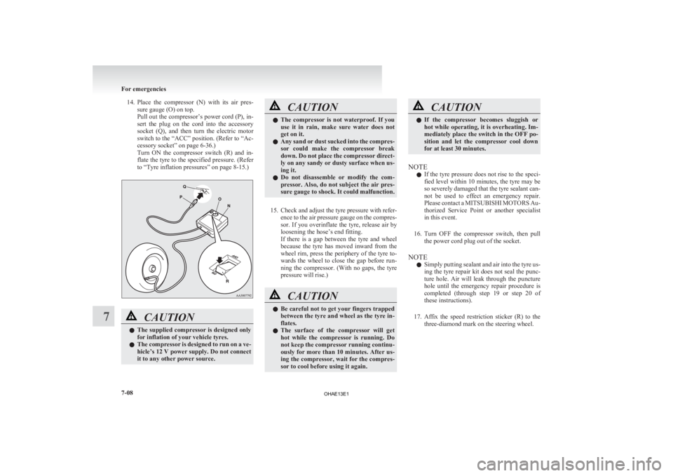
E01101800017Item Combined
Electric energy consumption [NEDC]
*
135 Wh/kmElectric range (Cruising range) [NEDC]
*
150 km (93 miles)
* : NEDC stands for New European Driving Cycle. The values of electric energy consumption and electric range are based on ECE R101. These values vary
depending on driving style, road and traffic conditions, ambient temperature, use of air conditioners and so forth. NOTE
l The results given do not express or imply any guarantee of the electric energy consumption of the particular vehicle.
The
vehicle itself has not been tested and there are inevitably differences between individual vehicles of the same model. In addition, this vehicle may incor-
porate particular modifications. Furthermore, the driver’s style and road and traffic conditions, as well as the extent to which the vehicle has been driven and
the standard of maintenance, will all affect its electric energy consumption.
l All mentioned values are referring to a new, driven in vehicle.
l The consumption, but mainly the driving distance depends on the condition of the traction battery.
l Parameters on traction battery are depending on temperature, climate, charging and charging history and age of the traction battery etc.
l A bigger influence as known by combustion engine are the energy consumptive consumers of the vehicle like heating, air conditioning, etc. Specifications
9-07 9
OHAE13E1