2013 MITSUBISHI iMiEV lock
[x] Cancel search: lockPage 212 of 258

CAUTION
l
Keep it out of reach of children.
l When
replacing the auxiliary battery, re-
move the connected positive (+) and nega-
tive (-) terminals after turning the electric
motor switch to the “LOCK” position
and waiting at least 1 minute. If the auxil-
iary battery terminal is removed just af-
ter the electric motor switch is turned to
the “LOCK” position, this may cause dam-
age to components of the electric motor
unit.
l Never short-circuit the auxiliary battery.
This could cause it to overheat and be dam-
aged.
l If the auxiliary battery is to be quick-
charged, first disconnect the battery ca-
bles.
l In order to prevent a short circuit, be
sure to disconnect the negative (-) termi-
nal first.
l Always wear protective eye goggles when
working near the auxiliary battery.
l Do not bring the nearby parts, the plastic
parts and so on into contact with sulphu-
ric acid (battery electrolyte) which may
crack, stain or discolour them.
If they are in contact, wipe off with soft
cloth, chamois or the like and an aqueous
solution of neutral detergent then imme-
diately rinse the affected parts with plen-
ty of water. NOTE
l Keep
the terminals clean. After the auxiliary
battery is connected, apply terminal protec-
tion grease. To clean the terminals, use luke-
warm water.
l Check to see if the auxiliary battery is secure-
ly installed and cannot be moved during trav-
el. Also check each terminal for tightness.
l When the vehicle is to be left unused for a
long period of time, remove the auxiliary bat-
tery and store it in a place where the battery
fluid will not freeze. The auxiliary battery
should be stored only in a fully charged con-
dition.
l It is necessary to adjust the electronic control-
led unit when the auxiliary battery is re-
moved for a long period of time.
Consult a MITSUBISHI MOTORS Author-
ized Service Point. Tyres
E08402800016 WARNING
l Driving
with tyres that are worn, dam-
aged or improperly inflated can lead to
loss of control or blowout of the tyres
which can result in a collision with seri-
ous or fatal injury. Vehicle care and Maintenance
8-14
8
OHAE13E1
Page 218 of 258

For cold and snowy weather
E08403700012
Ventilation slots
The
ventilation slots in front of the windscreen
should be kept clear of leaves or brushed clear after
heavy snowfall, so that the operation of the heating
and ventilation systems will not be impaired.
Weatherstripping
To prevent freezing of the weatherstripping on the
doors, bonnet, etc., they should be treated with sili-
cone grease.
Additional equipment
It is a good idea to carry a shovel or a short-han-
dled spade in the vehicle during the winter so that
you can clear away snow if you get stranded. A
small hand-brush for sweeping snow off the vehi-
cle and a plastic scraper for the windscreen and
rear window are also useful. Fusible links
E08403800013
The
fusible links will melt to prevent a fire if a
large current attempts to flow through certain elec-
trical systems.
In case of a melted fusible link, we recommend
you to have your vehicle inspected.
For the fusible links, please refer to “Passenger com-
partment fuse location table” on page 8-21 and
“Bonnet room fuse location table” on page 8-22. WARNING
l Fusible
links must not be replaced by any
other device. Failing to fit the correct fusi-
ble link may result in fire in the vehicle,
property destruction and serious or fatal
injuries at any time. Fuses
E08403900014
Fuse block location E08404000012
To prevent damage to the electrical system due to
shortcircuiting
or overloading, each individual cir-
cuit is provided with a fuse.
There are fuse blocks in the passenger compart-
ment and in the bonnet room.
NOTE
l Spare fuses are not provided. Please pur-
chase it from a MITSUBISHI MOTORS Au-
thorized Service Point or other locations.
Passenger compartment
The fuse block in the passenger compartment is lo-
cated in front of the driver’s seat at the position
shown in the illustration.
Press the tab (A) and remove the fuse cover (B). Vehicle care and Maintenance
8-20
8
OHAE13E1
Page 219 of 258

Bonnet room
In
the bonnet room, the fuse block is located as
shown in the illustration. Press the tab (A) and re-
move the cover. Fuse load capacity
E08404100013
The fuse capacity and the names of electrical sys-
tems
protected by the fuses are indicated on the
fuse block cover. Passenger compartment fuse location table
E08404200014 No. Sym-
bol Electrical system Capaci-
ties
1 Tail lamp (left)
7.5 A
2 Cigarette lighter/Ac-
cessory socket
15 A
3 — ——
4 Starter
7.5 A
5 Audio system amp
20 A
6 — ——
7 Tail lamp (right)
7.5 A
8 Outside rear-view mir-
rors
7.5 A
9 Control unit (Electric
motor unit)
7.5 A
* : Fusible link No. Sym-
bol Electrical system Capaci-
ties
10 Control unit
7.5 A
11 Rear fog lamp
10 A
12 Central door lock
15 A
13 Room lamp
10 A
14 Rear window wiper
15 A
15 Gauge
7.5 A
16 Relay
7.5 A
17 Heated seat
20 A
18 Option
10 A
19 Heated door mirror
7.5 A
20 Windscreen wiper
20 A
21 Reversing lamps
7.5 A
22 Demister
30 A
23 Heater
30 A
24 Auxiliary battery
30 A*
25 Radio
10 A
26 Electronic controlled
unit
15 A
* : Fusible link l
Some
fuses may not be installed on your ve-
hicle, depending on the vehicle model or spec-
ifications. Vehicle care and Maintenance
8-21 8
OHAE13E1
Page 220 of 258

l
The table above shows the main equipment
corresponding to each fuse.
Bonnet room fuse location table E08404300015No. Sym-
bol Electrical system Capaci-
ty
1 — ——
2 Auxiliary battery
30 A*
3 Electric motor switch
40 A*
4 Radiator fan motor
40 A*
5 Electric window con-
trol 40 A
*
6 Brake electric vacuum
pump 30 A
*
7 Electric motor unit con-
trol 15 A
8 Stop lamps 15 A
* : Fusible link No. Sym-
bol Electrical system Capaci-
ty
9 Front fog lamps 15 A
10 Water pump (Electric
motor unit) 15 A
11 Charge 10 A
12 Hazard warning flasher 10 A
13 Horn 10 A
14 Daytime running lamps 10 A
15 Traction battery cool-
ing fan motor 15 A
16 Water pump (Air con-
ditioning) 10 A
17 Headlamp low beam
(right) 20 A
18 Headlamp low beam
(left) 20 A
19 Headlamp high-beam
(right) 10 A
20 Headlamp high-beam
(left) 10 A
* : Fusible link l
Some
fuses may not be installed on your ve-
hicle, depending on the vehicle model or spec-
ifications.
l The table above shows the main equipment
corresponding to each fuse. Identification of fuse
E08404400016 Capacity Colour
7.5 A Brown
10 A Red
15 A Blue
20 A Yellow
30 A Green (fuse type) / Pink (fusible
link type)
40 A Green (fusible link type) Fuse replacement
E08404500017
1. Before
replacing a fuse, always turn off the
electrical circuit concerned and turn the elec-
tric motor switch to the “LOCK” position.
2. Remove the fuse puller (A) from the inside of the fuse cover in the passenger compart-
ment. 3. Referring
to the fuse load capacity table,
check the fuse pertaining to the problem. Vehicle care and Maintenance
8-22
8
OHAE13E1
Page 221 of 258

B- Fuse is OK
C- Blown fuse
NOTE l If
any system does not function but the fuse
corresponding to that system is normal, there
may be a fault in the system elsewhere. We
recommend you to have your vehicle checked.
4. Insert a new fuse of the same capacity by us- ing the fuse puller into the same place at the
fuse block. CAUTION
l
If
the newly inserted fuse blows again af-
ter a short time, we recommend you to
have the electrical system checked to find
the cause and rectify it.
l Never use a fuse with a capacity larger
than that specified or any substitute, such
as wire, foil, etc.; doing so will cause the
circuit wiring to heat up and this could
cause fire. Replacement of lamp bulbs
E08404600018
Before
replacing a bulb, ensure the lamp is off. Do
not touch the glass part of the new bulb with your
bare fingers; the skin oil left on the glass will evap-
orate when the bulb gets hot and the vapour will
condense on the reflector and dim the surface. CAUTION
l
Bulbs
are extremely hot immediately af-
ter being turned off.
When replacing a bulb, wait for it to cool
sufficiently before touching it. You could
otherwise be burnt.
NOTE l If
you are unsure of how to carry out the
work as required, we recommend you to con-
sult a specialist.
l Be careful not to scratch the vehicle body
when removing a lamp or lens.
l When it rains or when the vehicle has been
washed, the inside of the lens sometimes be-
comes foggy. This is the same phenomenon
as when window glass mists up on a humid
day, and does not indicate a functional prob-
lem.
When the lamp is switched on, the heat will
remove the fog. However, if water gathers in-
side the lamp, we recommend you to have
the lamp checked.
Bulb capacity E08404700019
When replacing a bulb, use a new bulb with the
same wattage and colour. Vehicle care and Maintenance
8-23 8
OHAE13E1
Page 226 of 258

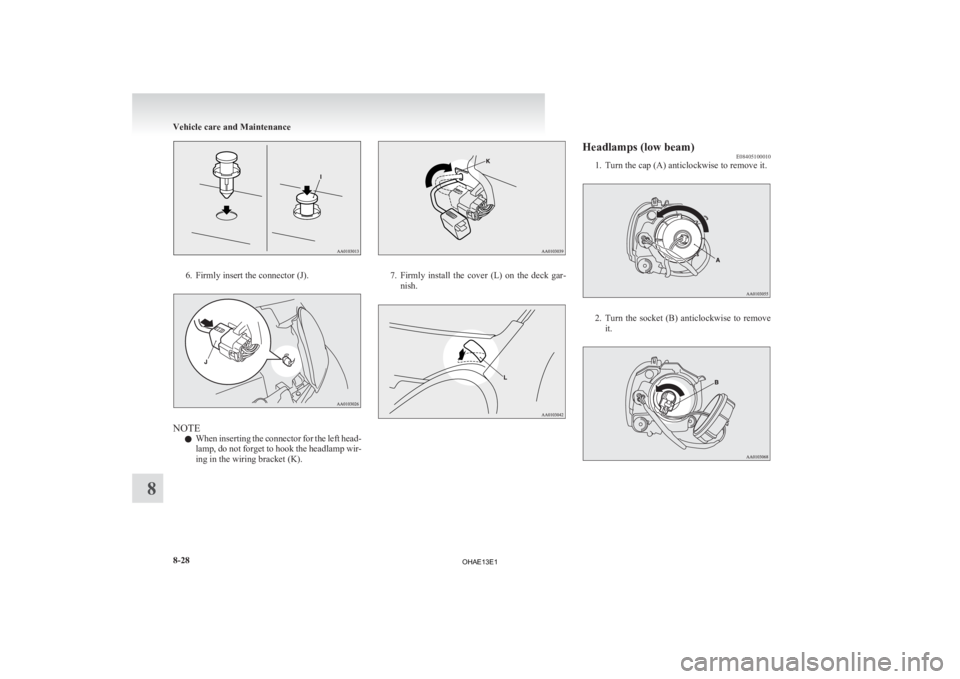
6. Firmly insert the connector (J).
NOTE
l When
inserting the connector for the left head-
lamp, do not forget to hook the headlamp wir-
ing in the wiring bracket (K). 7. Firmly
install the cover (L) on the deck gar-
nish. Headlamps (low beam)
E08405100010
1.
Turn the cap (A) anticlockwise to remove it. 2. Turn
the socket (B) anticlockwise to remove
it. Vehicle care and Maintenance
8-28
8
OHAE13E1
Page 227 of 258

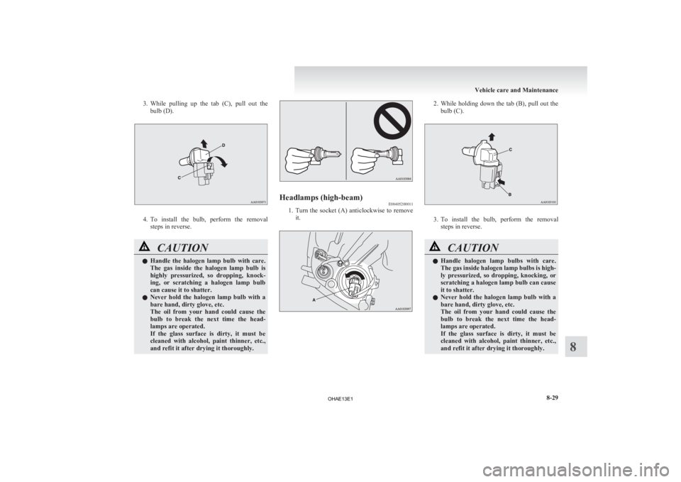
3. While pulling up the tab (C), pull out the
bulb (D). 4. To
install the bulb, perform the removal
steps in reverse. CAUTION
l
Handle
the halogen lamp bulb with care.
The gas inside the halogen lamp bulb is
highly pressurized, so dropping, knock-
ing, or scratching a halogen lamp bulb
can cause it to shatter.
l Never hold the halogen lamp bulb with a
bare hand, dirty glove, etc.
The oil from your hand could cause the
bulb to break the next time the head-
lamps are operated.
If the glass surface is dirty, it must be
cleaned with alcohol, paint thinner, etc.,
and refit it after drying it thoroughly. Headlamps (high-beam)
E08405200011
1. Turn
the socket (A) anticlockwise to remove
it. 2. While
holding down the tab (B), pull out the
bulb (C). 3. To
install the bulb, perform the removal
steps in reverse. CAUTION
l
Handle
halogen lamp bulbs with care.
The gas inside halogen lamp bulbs is high-
ly pressurized, so dropping, knocking, or
scratching a halogen lamp bulb can cause
it to shatter.
l Never hold the halogen lamp bulb with a
bare hand, dirty glove, etc.
The oil from your hand could cause the
bulb to break the next time the head-
lamps are operated.
If the glass surface is dirty, it must be
cleaned with alcohol, paint thinner, etc.,
and refit it after drying it thoroughly. Vehicle care and Maintenance
8-29 8
OHAE13E1
Page 228 of 258

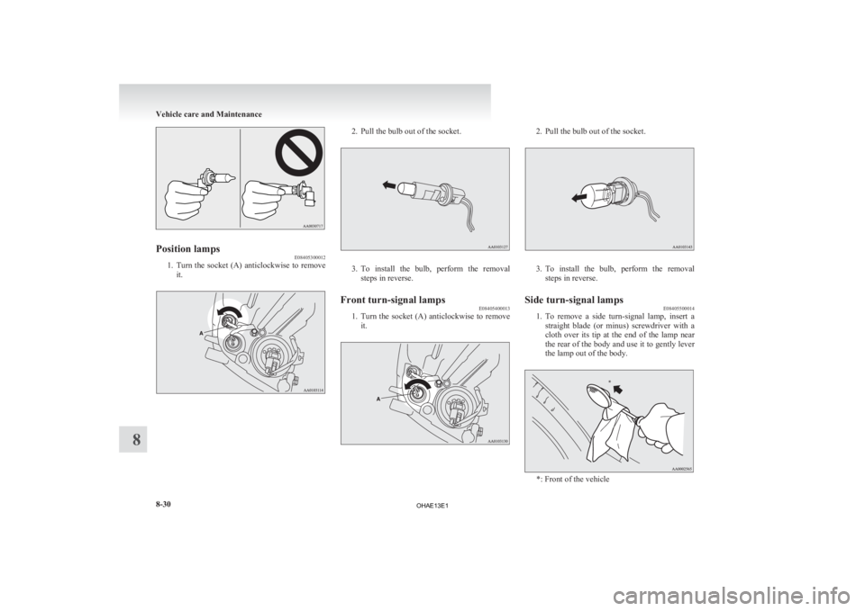
Position lamps
E08405300012
1. Turn the socket (A) anticlockwise to remove
it. 2. Pull the bulb out of the socket.
3. To install the bulb, perform the removal
steps in reverse.
Front turn-signal lamps E08405400013
1. Turn
the socket (A) anticlockwise to remove
it. 2. Pull the bulb out of the socket.
3. To
install the bulb, perform the removal
steps in reverse.
Side turn-signal lamps E08405500014
1. To
remove a side turn-signal lamp, insert a
straight blade (or minus) screwdriver with a
cloth over its tip at the end of the lamp near
the rear of the body and use it to gently lever
the lamp out of the body. *: Front of the vehicleVehicle care and Maintenance
8-30
8 *
OHAE13E1