2013 MINI Paceman change wheel
[x] Cancel search: change wheelPage 83 of 275

CONTROLSTechnology for driving comfort and safety
82
upholstery in the center of the steering wheel,
on the instrument panel, the doors, and the roof
pillars as well as the sides of the headliner. Do
not attempt to remove or dismantle the steering
wheel.<
Do not touch the individual components
immediately after the system has been
triggered, because there is a danger of burns.
Have the testing, repair, removal, and disposal
o f a i r b a g g e n e r a t o r s e x e c u t e d o n l y b y y o u r M I N I
dealer or a workshop that has the required
explosives licenses.
Otherwise, unprofessiona l attempts to service
the system could lead to failure in an emergency
or undesired airbag activation, either of which
could result in personal injury. <
Warning notices and information about the air-
bags can also be found on the sun visors.
Automatic deactivation of the front
passenger airbags
The presence of a passenger in the front passen-
ger seat is detected by measuring the resistance
of the human body. The system correspondingly
activates or deactivates the front, side, and knee
airbags for the front passenger.
Make sure that the front passenger's feet
remain in the footwell; otherwise, it is not
possible to guarantee the function of the front
passenger airbags.<
The indicator lamp above the interior rearview
mirror shows the current st atus of the front pas-
senger airbags, deactivated or activated, refer to
Status of front passe nger airbags below.
Before transporting a child on the front
passenger seat, read the safety informa-
tion and follow the instru ctions under Transport-
ing children safely, page 46.<
Malfunction of the automatic
deactivation
When teenagers and adults assume certain sit-
ting positions, this can cause the front, side, and
knee airbags to deactivate. The indicator lamp for the front passenger airbags lights up when
this occurs. In such case
s, the passenger should
change his or her sitting position so that the
front passenger airbags are activated and the
indicator lamp goes out. If the desired airbag
status cannot be achieved by changing the sit-
ting position, transport the relevant passenger
on a rear seat.
> Do not attach covers, cushions, ball mats or
other items to the front passenger seat
unless they are specif ically recommended
by the manufacturer of your MINI.
> Do not place items on the front passenger
seat.
> Do not place items under the seat which
could press against the seat from below.
Status of front passenger airbags
The indicator lamp for the front passenger air-
bags shows the functional status of the front
passenger's front, side, and knee airbags in
accordance with whet her and how the front
passenger seat is occupied. The indicator lamp
shows whether the front passenger airbags are
activated or deactivated.
> The indicator lamp lights up when a child in
a specially designated child restraint system
is properly detected on the seat or the seat is
unoccupied.
The front, side, and knee airbags for the
front passenger are not activated.
Most child seats are detected by the
system. This particularly applies to
child seats that were required by NHTSA at
the time of manufacture of the vehicle. After
00320051004F004C00510048000300280047004C0057004C005200510003
Page 141 of 275

EntertainmentOn/off and tone
140
On/off and tone
Vehicle equipment
In this chapter, all production, country, and
optional equipment that is offered in the model
range is described. Equipment is also described
that is not available because of, for example,
selected options or coun try version. This also
applies to safety relate d functions and systems.
General information
The following audio source s have shared control
elements and setting options:
> Radio
> CD player
> External devices, e.g. MP3 player
Controls
The audio sources can be operated using:
>Buttons near the CD player
> Onboard computer
> Buttons on the steering wheel, refer to
page 10
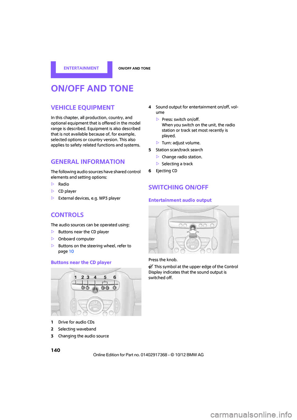
Buttons near the CD player
1Drive for audio CDs
2 Selecting waveband
3 Changing the audio source 4
Sound output for ente rtainment on/off, vol-
ume
> Press: switch on/off.
When you switch on the unit, the radio
station or track set most recently is
played.
> Turn: adjust volume.
5 Station scan/track search
>Change radi o station.
> Selecting a track
6 Ejecting CD
Switching on/off
Entertainment audio output
Press the knob.
This symbol at the upper edge of the Control
Display indicates that the sound output is
switched off.
00320051004F004C00510048000300280047004C0057004C005200510003
Page 142 of 275

On/off and toneEntertainment
141
Adjusting volume
Turn the knob to the desired volume.
The volume can also be adjusted on the steering
wheel, refer to page10.
The setting is stored for the remote control cur-
rently in use; refer to Personal Profile, page 26.
Setting tone controls
Various tone settings can be changed, e.g. treble
and bass or the speed-dependent volume con-
trol.
The tone settings are set for all audio sources at
once.
The settings are stored for the remote control
currently in use; refer to Personal Profile,
page 26.
Treble, bass, balance, fader
> "Treble": treble adjustment.
> "Bass": bass adjustment.
> "Balance": volume distribution right/left.
> "Fader": volume distribution front/back.
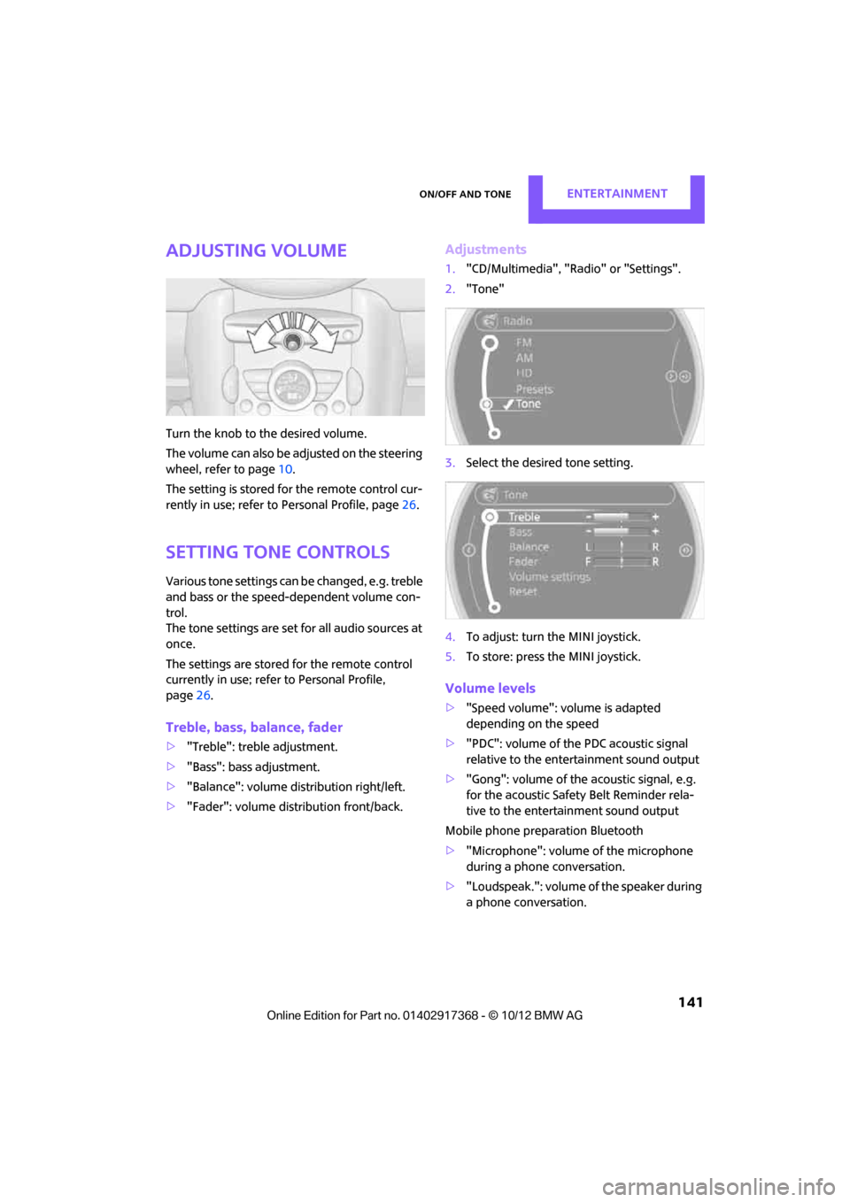
Adjustments
1."CD/Multimedia", "Rad io" or "Settings".
2. "Tone"
3. Select the desired tone setting.
4. To adjust: turn the MINI joystick.
5. To store: press the MINI joystick.
Volume levels
>"Speed volume": vo lume is adapted
depending on the speed
> "PDC": volume of the PDC acoustic signal
relative to the entertainment sound output
> "Gong": volume of the acoustic signal, e.g.
for the acoustic Safety Belt Reminder rela-
tive to the entertainment sound output
Mobile phone preparation Bluetooth
> "Microphone": volume of the microphone
during a phone conversation.
> "Loudspeak.": volume of the speaker during
a phone conversation.
00320051004F004C00510048000300280047004C0057004C005200510003
Page 197 of 275

COMMUNICATIONSMINI Connected
196
Connecting via the snap-in adapter
The mobile phone can also be connected using
the snap-in adapter, refer to page185.
Using MINI Connected
After successful connection of the mobile phone
to the vehicle and activation of MINI Connected,
the applications are di splayed on the Control
Display and can be operated using the MINI joy-
stick.
Volume adjustments can be made using the
buttons on the steering wheel, refer to page 10,
or using the volume control knob on the radio,
refer to page 141.
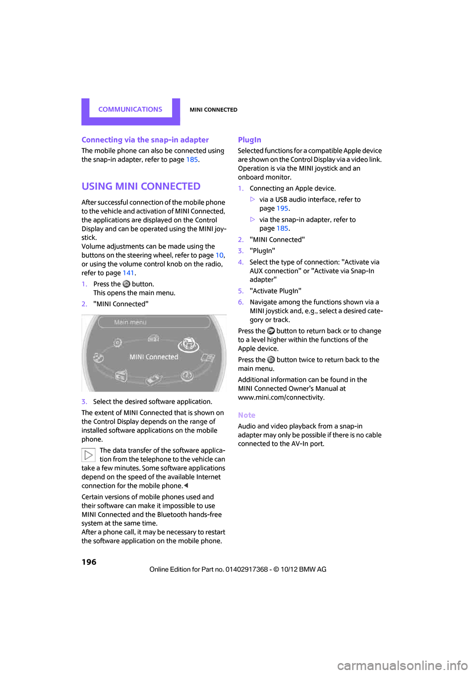
1. Press the button.
This opens the main menu.
2. "MINI Connected"
3. Select the desired so ftware application.
The extent of MINI Connected that is shown on
the Control Display depends on the range of
installed software applic ations on the mobile
phone.
The data transfer of the software applica-
tion from the telephone to the vehicle can
take a few minutes. Some software applications
depend on the speed of the available Internet
connection for the mobile phone. <
Certain versions of mobile phones used and
their software can make it impossible to use
MINI Connected and the Bluetooth hands-free
system at the same time.
After a phone call, it may be necessary to restart
the software application on the mobile phone.
PlugIn
Selected functions for a compatible Apple device
are shown on the Control Display via a video link.
Operation is via the MINI joystick and an
onboard monitor.
1. Connecting an Apple device.
>via a USB audio interface, refer to
page 195.
> via the snap-in adapter, refer to
page 185.
2. "MINI Connected"
3. "PlugIn"
4. Select the type of connection: "Activate via
AUX connection" or "Activate via Snap-In
adapter"
5. "Activate PlugIn"
6. Navigate among the functions shown via a
MINI joystick and, e.g., select a desired cate-
gory or track.
Press the button to return back or to change
to a level higher within the functions of the
Apple device.
Press the button twice to return back to the
main menu.
Additional information can be found in the
MINI Connected Owner's Manual at
www.mini.com/c onnectivity.
Note
Audio and video playba ck from a snap-in
adapter may only be possible if there is no cable
connected to the AV-In port.
00320051004F004C00510048000300280047004C0057004C005200510003
Page 214 of 275

Wheels and tiresMOBILITY
213
puncture, refer to page78. Your MINI dealer will
be glad to advise you.
Recommended tire brands
For each tire size, the manufacturer of your MINI
recommends certain tire brands. They are
marked with a clearly visible MINI designation
on the sidewall of the tire.
When properly used, these tires meet the high-
est standards in terms of safety and handling
characteristics.
Run-flat tires
When mounting new tires or changing over from
summer to winter tires and vice versa, mount
run-flat tires for your ow n safety. Keep in mind
that no space-saver spare tire is available in the
event of a flat. Your MINI dealer will be glad to
advise you.
Special characteristics of winter tires
The manufacturer of your MINI recommends the
use of winter tires on snowy roads or if temper-
atures drop below 45 7/+7 6. Although all-
season M+S tires provide better winter traction
than summer tires, they generally fail to provide
the same levels of cold-weather performance as
winter tires.
Pay attention to speed
Always comply with the speed limit for the
winter tires mounted on your car; failure
to do so could result in tire damage and acci-
dents. < If the car is capable of
speeds higher than that
permitted for the winter ti res, a label stating the
maximum permitted speed for the mounted
tires must be displayed in your field of view. This
label is available at your tire dealer or MINI
dealer.
Storage
Always store wheels and tires in a cool, dry place
with as little exposure to light as possible.
Always protect tires agains t all contact with oil,
grease and fuels.
Do not exceed the maximum tire inflation pres-
sure indicated on the side wall of the tire.
Swapping wheels among the axles
Depending on the individual use, front and rear
tires may exhibit diff erent wear and tear.
In order to maintain an even wear and tear, the
wheels may be rotated between the axles. Your
MINI dealer will be glad to advise you.
Always check the inflation pressure after the tire
rotation, if necessary change the pressure.
Snow chains
Only certain types of fi ne-link snow chains have
been tested by the manufacturer of your MINI,
classified as road-saf e and recommended. Con-
tact your MINI deal er for more details.
Only attach snow chains in pairs to the front
wheels with the following tires.
> 195/60 R 16 M+S
Observe the manufacturer's instructions when
mounting snow chains. Do not exceed a speed
of 30 mph or 50 km/h. Do not initialize the Flat Tire Monitor if
snow chains are mounted; otherwise, the
instrument might issue an incorrect reading.
When driving with snow chains, it can be useful
to briefly deactivate DSC or activate DTC, refer to
page 73.<
00320051004F004C00510048000300280047004C0057004C005200510003
Page 227 of 275

MOBILITYReplacing components
226
Accessing the lamp from the engine
compartment
The low-beam/high-beam bulb can be changed
from the engine compartment.
Removing the cover:
1.Press the tab.
2. Flip open the cover and take it out of the
holder.
Follow the same steps in reverse order to reat-
tach the cover.
Replacing the bulb
1. Turn the lamp counterclockwise, arrow 1,
and remove it, arrow 2.
2. Push on the catch, arrow 1, and disconnect
the connector, arrow 2. 3.
To insert the new bulb and replace the
cover, proceed in reverse order.
Turn signals, parking lamps, roadside
parking lamps, and fog lamps
Accessing the lamps via the wheel well
1Turn signal
2 Parking/roadside parking/fog lamps
Replacing a turn signal bulb
21 watt bulb, P21W, if necessary PY 21 W
1.Turn in the wheel.
2. Remove cover 1.
To do so, turn the cover counterclockwise.
3. Remove the inside cover.
To do so, turn the cover counterclockwise.
00320051004F004C00510048000300280047004C0057004C005200510003
Page 233 of 275

MOBILITYReplacing components
232
Correct the tire inflation pressure
1.After driving approx. 3.1 miles/5 km or
ten minutes, stop at a suitable location.
2. Screw the connection hose 6 of the com-
pressor directly onto the tire valve.
3. Insert the plug 5 into the power socket in
the vehicle interior.
4. Adjust tire pressure to 1.8 bar/26 psi. With
the engine running:
> To increase the inflatio n pressure: switch on
the compressor. To ch eck the current infla-
tion pressure, switch off the compressor.
Do not run the comp ressor for longer
than 10 minutes; otherwise, the
device will overheat and possibly be dam-
aged.<
> To decrease the inflation pressure: press the
release button 9.
If the tire cannot m aintain the inflation
pressure, drive the vehicle again, refer to
Distributing the sealan t. Then repeat steps
1to4.
If an inflation pressure of 1.8 bar/26 psi still can-
not be reached, then the tire is too heavily dam-
aged. Contact your ne arest MINI dealer.<
Driving on
Do not exceed the permitted maximum
speed of 50 mph/80 km/h; doing so may
result in an accident. <
Replace the defective tire as soon as possible
and have the new wheel/tire assembly bal-
anced.
Have the Mobility Kit refilled.
Changing wheels
The tire change set is available from as an
optional accessory at your MINI dealer.
Preparing for a wheel change
Observe the safety precautions regarding
flat tires on page 230.<
Additional safety measures when chang-
ing tires:
Only change the tire wh en parked on a surface
that is level, firm and not slippery.
The vehicle or the jack could slip sideways on
soft or slippery support surfaces, such as snow,
ice, flagstones, etc.
Do not use a wooden block or similar object as a
support base for the jack, as this would prevent
it from extending to its full support height and
reduce its load-carrying capacity.
Do not lie under the vehicle or start the engine
when the vehicle is supported by the jack; other-
wise, there is a risk of fatal injury. <
1. Place the foldable chock
behind the front
wheel on the other side of the vehicle or in
front of the wheel if the vehicle is on an
incline. If the wheel is changed on a surface
with a more severe sl ope, take additional
precautions to secure the vehicle from roll-
ing.
2. Uncover the lug bolts if necessary.
3. Loosen the lug bolts by a half turn.
Jacking up the vehicle
The vehicle jack is designed for changing
wheels only. Do not attempt to raise
another vehicle model with it or to raise any load
of any kind. To do so could cause accidents and
personal injury. <
1. Place the jack at the jacking point closest to
the wheel.
The jack base must be perpendicular to the
surface beneath the jacking point.
00320051004F004C00510048000300280047004C0057004C005200510003
Page 265 of 275

REFERENCEEverything from A to Z
264
Engine malfunction
– indicator lamp13
Engine oil
– additives, refer to Approved
engine oils 216
– alternative oil types 216
– approved engine oils 216
– capacity 216
– checking level 215
– dipstick 215
– intervals between changes, refer to Service
requirements 64
– MINI Maintenance System 218
Engine oil level, checking 215
Engine output, refer to Engine data 244
Engine starti ng, refer to
Starting the engine 51
Entering destination 120
Entering intersection 121
Entertainment sound output on/off 140
Entry map for destination 125
ESP Electronic Stability Program, refer to Dynamic
Stability Control DSC 72
Exhaust system, refer to Hot exhaust system 105
Exterior mirrors 44
– adjusting 44
– automatic dimming
feature 45
– automatic heating 45
– folding in and out 44
External audio device 97
External audio device, refer to AUX-In connection 153
External care 220
External devices
– random play sequence 156
– Software update 161
External temperature display
– change units of measure 64
– in the onboard computer 64External temperature
warning 61
Eyes
– for tow-starting and towing
away 238
– for tying down loads 112
F
Failure messages, refer to
Check Control 67
Failure of an electrical consumer 234
Fastening safety belts, refer to Safety belts 42
Fastest route for
navigation 129
Fast forward
– CD player 152
Fault messages, refer to Check Control 67
Faulty
– tire 76
Filter
– microfilter/activated-
charcoal filter for automatic
climate control 91
– microfilter for air
conditioner 89
Fine wood, care 223
First aid pouch 236
Fixture for remote control, refer to Ignition lock 50
Flash when locking/ unlocking 28
Flat load floor 109
Flat tire
– run-flat tires 212
– Tire Pressure Monitor TPM 77
Flat Tire Monitor FTM 75
– indicating a flat tire 76
– initializing the system 75
– snow chains 75
– system limits 75
Flat tires, refer to Tire
condition 211
Floor mats, care 222 Floor plate, refer to Flat load
floor 109
FM, waveband 143
Fog lamps
– replacing bulb 226
Folding rear seat backrest 106
Footbrake, refer to Braking
safely 105
Footwell lamps 87
For your own safety 4
Four-wheel drive, refer to ALL4 74
Front airbags 81
Front fog lamps 86
– replacing bulb 226
Front seat adjustment 39
Frost on windows, refer to Defrosting windows 89,91
FTM, refer to Flat Tire
Monitor 75
Fuel 201
– gauge 60
– high-quality brands 201
– quality 201
– specificati
o
ns201
– tank capacity 251
Fuel clock, refer to Fuel gauge 60
Fuel consumption display
– average fuel consumption 61
Fuel display, refer to Fuel gauge 60
Fuel filler flap 200
– releasing in the event of electrical malfunction 200
Fuses 234
G
Garage door opener, refer to
Integrated universal remote
control 93
Gasoline
– refer to Average fuel consumption 61
Gasoline, refer to Required fuel 201
00320051004F004C00510048000300280047004C0057004C005200510003