2013 MERCEDES-BENZ SL-CLASS ROADSTER lock
[x] Cancel search: lockPage 538 of 572

i
Canada only:
This device complies with RSS-210
of
Industry Canada. Operation is subject to
the following two conditions:
1. This device may not cause harmful
interference, and
2. this device must accept any interference
received, including interference that may
cause undesired operation of the device.
Any unauthorized modification to this
device could void the user’s authority to
operate the equipment.
Checking tire pressure electronically X
Make sure that the key is in position
2(Y page 135) in the ignition lock.
X Press the = or ; button on the
steering wheel to select the Service
menu.
X Press the 9 or : button to select
Tire Pressure.
X Press the a button.
The current
tire pressure for each wheel will
be displayed in the multifunction display.
If the vehicle has been parked for over
20 minutes, the message Tire pressure
will be displayed after driving a
few minutes appears.
After a teach-in period, the tire pressure
monitor automatically
recognizes new wheels
or new sensors. As long as a clear allocation
of the tire pressure values to the individual
wheels is not possible, the Tire Pressure
Monitor Active display message is shown
instead of the tire pressure display. The tire
pressures are already being monitored.
Tire pressure monitor warning
messages If the tire pressure monitor detects a
significant
pressure
loss on one or more tires,
a warning message is shown in the
multifunction display. A warning tone also sounds and the tire pressure warning lamp
lights up in the instrument cluster.
Each
tire
that is affected by a significant loss
of pressure is highlighted in the pressure
display.
X If the Correct Tire Pressure message
appears in
the multifunction display, check
the tire pressure on all four wheels and
correct it if necessary.
i If the wheel positions on the vehicle are
interchanged, the tire pressures may be
displayed for the wrong positions for a
short time. This is rectified after a few
minutes of driving, and the tire pressures
are displayed for the correct positions.
Restarting the tire pressure monitor When you restart the tire pressure monitor,
all
existing
warning messages are deleted and
the warning lamps go out. The monitor uses
the currently set tire pressures as the
reference values for monitoring. In most
cases, the tire pressure monitor will
automatically detect the new reference
values after you have changed the tire
pressure. However, you can also define
reference values manually as described here.
X Set the tire pressure to the value
recommended for the corresponding
driving situation on the Tire and Loading
Information placard on the driver's side
B-pillar( Y page 529).
Additional tire
pressure values for different
loads can also be found on the tire pressure
table on the inside of the fuel filler flap
(Y page 529).
X Make sure that the tire pressure is correct
on all four wheels.
X Make sure that the SmartKey is in position
2 in the ignition lock.
X Press the = or ; button on the
steering wheel to select the Service
menu.536
Tire pressure
Wheels and tires
Page 550 of 572

Rotate front and rear wheels only if the wheels
and tires are of the same dimensions.
! On vehicles
equipped with a tire pressure
monitor, electronic components are
located in the wheel.
Tire-mounting tools should not be used
near the valve. This could damage the
electronic components.
Only have tires changed at a qualified
specialist workshop.
Always pay attention to the instructions and
safety notes when changing a wheel
(Y page 548).
The wear patterns on the front and rear tires
differ, depending on the operating conditions.
Rotate the wheels before a clear wear pattern
has formed on the tires. Front tires typically
wear more on the shoulders and the rear tires
in the center.
If your vehicle's tire configuration allows, you
can rotate the wheels according to the
intervals in the tire manufacturer's warranty
book in your vehicle documents. If this is not
available, the tires should then be replaced
every 3000 to 6000 miles (5000 to
10,000 km), or earlier if the tire wear requires
this. Do not change the direction of wheel
rotation.
Clean the contact surfaces of the wheel and
the brake disc thoroughly every time a wheel
is interchanged. Check the tire pressure and,
if necessary, restart the tire pressure loss
warning system or the tire pressure monitor. Direction of rotation
Tires with a specified direction of rotation
have additional
benefits, e.g. if there is a risk
of hydroplaning. You will only gain these
benefits if the correct direction of rotation is
maintained.
An arrow on the sidewall of the tire indicates
its correct direction of rotation. Storing wheels
Store wheels
that are not being used in a cool,
dry and preferably dark place. Protect the
tires from oil, grease, gasoline and diesel. Cleaning the wheels
G
WARNING
Do not use power washers with circular-jet
nozzles (dirt
grinders) to clean your vehicle, in
particular the tires. You could otherwise
damage the tires and cause an accident. Mounting a wheel
Preparing the vehicle X
Stop the vehicle on solid, non-slippery and
level ground.
X Unload the vehicle. The jack can only be
used when the vehicle is unladen.
X Apply the electric parking brake manually.
X Bring the front wheels into the straight-
ahead position.
X Shift the transmission to position P
.
X Switch off the engine.
X Vehicles without KEYLESS-GO: remove
the SmartKey from the ignition lock.
X Vehicles with KEYLESS-GO: open the
driver's door.
The on-board electronics have status 0,
which is the same as the SmartKey having
been removed.
X Vehicles with KEYLESS-GO: remove the
Start/Stop button from the ignition lock
(Y page 135).
X If included in the vehicle equipment,
remove the tire-change tool kit from the
vehicle.
X Secure the vehicle to prevent it from rolling
away.548
Changing a wheel
Wheels and tires
Page 552 of 572

R
before raising the vehicle, secure it from
rolling away by applying the parking brake
and inserting wheel chocks. Never
disengage the parking brake while the
vehicle is raised.
R the jack must be placed on a firm, flat and
non-slip surface. On a loose surface, a
large, load-bearing
underlay must be used.
On a slippery surface, a non-slip underlay
must be used, e.g. rubber mats.
R do not use wooden blocks or similar
objects as a jack underlay. Otherwise, the
jack will not be able to achieve its load-
bearing capacity due to the restricted
height.
R make sure that the distance between the
underside of the tires and the ground does
not exceed 1.2 in (3 cm).
R never place your hands and feet under the
raised vehicle.
R never lie under the raised vehicle.
R never start the engine when the vehicle is
raised.
R never open or close a door or the trunk lid
when the vehicle is raised.
R make sure that no persons are present in
the vehicle when the vehicle is raised. X
Using lug wrench :, loosen the bolts on
the wheel
you wish to change by about one
full turn. Do not unscrew the bolts
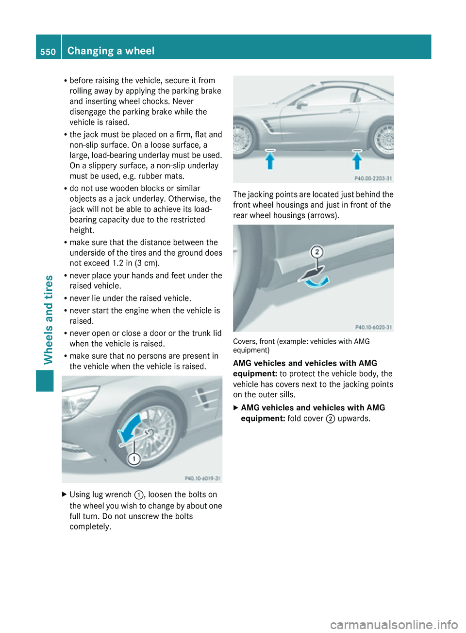
completely. The jacking points are located just behind the
front wheel housings and just in front of the
rear wheel housings (arrows).
Covers, front (example: vehicles with AMG
equipment)
AMG vehicles and vehicles with AMG
equipment:
to protect the vehicle body, the
vehicle has covers next to the jacking points
on the outer sills.
X AMG vehicles and vehicles with AMG
equipment: fold cover ; upwards.550
Changing a wheel
Wheels and tires
Page 553 of 572

=
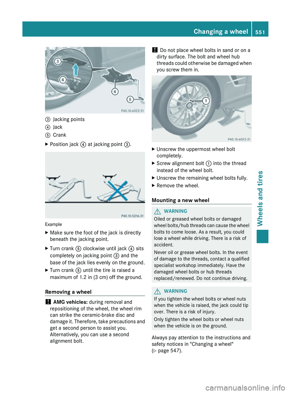
Jacking points
? Jack
A Crank
X Position jack ? at jacking point =.Example
X
Make sure the foot of the jack is directly
beneath the jacking point.
X Turn crank A clockwise until jack ? sits
completely on jacking point = and the
base of the jack lies evenly on the ground.
X Turn crank A until the tire is raised a
maximum of 1.2 in (3 cm ) off the ground.
Removing a wheel !
AMG vehicles: during removal and
repositioning of the wheel, the wheel rim
can strike the ceramic-brake disc and
damage it.
Therefore, take precautions and
get a second person to assist you.
Alternatively, you can use a second
alignment bolt. !
Do not place wheel bolts in sand or on a
dirty surface. The bolt and wheel hub
threads could
otherwise be damaged when
you screw them in. X
Unscrew the uppermost wheel bolt
completely.
X Screw alignment bolt : into the thread
instead of the wheel bolt.
X Unscrew the remaining wheel bolts fully.
X Remove the wheel.
Mounting a new wheel G
WARNING
Oiled or greased wheel bolts or damaged
wheel bolts/hub
threads can cause the wheel
bolts to come loose. As a result, you could
lose a wheel while driving. There is a risk of
accident.
Never oil or grease wheel bolts. In the event
of damage to the threads, contact a qualified
specialist workshop immediately. Have the
damaged wheel bolts or hub threads
replaced/renewed. Do not continue driving. G
WARNING
If you tighten the wheel bolts or wheel nuts
when the vehicle is raised, the jack could tip
over. There is a risk of injury.
Only tighten the wheel bolts or wheel nuts
when the vehicle is on the ground.
Always pay attention to the instructions and
safety notices in "Changing a wheel"
(Y page 547). Changing a wheel
551
Wheels and tires Z
Page 554 of 572

Only use wheel bolts that have been designed
for the wheel and the vehicle. For safety
reasons, Mercedes-Benz recommends that
you only use wheel bolts which have been
approved
for
Mercedes-Benz vehicles and the
respective wheel.
! AMG vehicles: during removal and
repositioning of the wheel, the wheel rim
can strike the ceramic-brake disc and
damage it. Therefore, take precautions and
get a second person to assist you.
Alternatively, you can use a second
alignment bolt.
! To prevent damage to the paintwork, hold
the wheel securely against the wheel hub
while screwing in the first wheel bolt. X
Clean the wheel and wheel hub contact
surfaces.
X Slide the wheel to be mounted onto the
alignment bolt and push it on.
X Tighten the wheel bolts until they are
finger-tight.
X Unscrew the alignment bolt.
X Tighten the last wheel bolt until it is finger-
tight.
Lowering the vehicle G
WARNING
The wheels could work loose if the wheel nuts
and bolts are not tightened to the specified
tightening torque. There is a risk of accident. Have the tightening torque immediately
checked at a qualified specialist workshop
after a wheel is changed.
X
Turn the crank of the jack counter-
clockwise until the vehicle is once again
standing firmly on the ground.
X Place the jack to one side.
X Tighten the wheel bolts evenly in a
crosswise pattern in the sequence
indicated ( : to A). The specified
tightening torque is 96 lb-ft(130 Nm).
X Turn the jack back to its initial position.
X Stow the jack and the rest of the vehicle
tools in the trunk again.
X AMG vehicles and vehicles with AMG
equipment: insert
the cover into the outer
sill.
X Check the tire pressure of the newly
mounted wheel and adjust it if necessary.
Make sure to observe the recommended
tire pressure ( Y page 529).
i Vehicles with tire pressure monitor: all
wheels mounted must be equipped with
functioning sensors. Wheel and tire combinations
General notes
! For safety reasons, Mercedes-Benz
recommends that you only use tires and
wheels which have been approved by
Mercedes-Benz specifically for your
vehicle. 552
Wheel and tire combinationsWheels and tires
Page 567 of 572

!
Do not
add distilled or de-ionized water to
the washer fluid container. Otherwise, the
level sensor may be damaged.
! Only MB SummerFit and MB WinterFit
washer fluid should be mixed together. The
spray nozzles may otherwise become
blocked.
At temperatures above freezing:
X Fill the washer fluid reservoir with a mixture
of water and windshield washer fluid, e.g.
MB SummerFit.
X Add 1 part MB SummerFit to 100 parts
water.
At temperatures below freezing:
X Fill the washer fluid reservoir with a mixture
of water and windshield washer fluid, e.g.
MB WinterFit.
Adapt the mixing ratio to the
outside temperature.
X Down to 14 ‡ (Ò10 †): mix 1 part MB
WinterFit with 2 parts water.
X Down to Ò4 ‡ (Ò20 †): mix 1 part MB
WinterFit with 1 part water.
X Down to Ò20.2 ‡ (
Ò29 †): mix 2 parts MB
WinterFit with 1 part water. Model Capacity
All models
5.6 US qt(5.3 l)
i
Add windshield washer fluid, e.g. MB
SummerFit or MB WinterFit, to the washer
fluid all year round. Vehicle data
General notes
Please note that for the specified vehicle
data:
R The heights specified may vary as a result
of:
-tires
- load
- condition of the suspension
- optional equipment
R The vehicle length specified includes the
front license plate adapter. Dimensions and weights
All models (except
AMG vehicles)
:Opening height 75.8 in (1925 mm)
AMG vehicles
:Opening height 75.6 in – 79.3 in
(1921 mm –2013 mm ) Vehicle data
565
Technical data Z