2013 MERCEDES-BENZ GLK-CLASS SUV engine
[x] Cancel search: enginePage 268 of 380
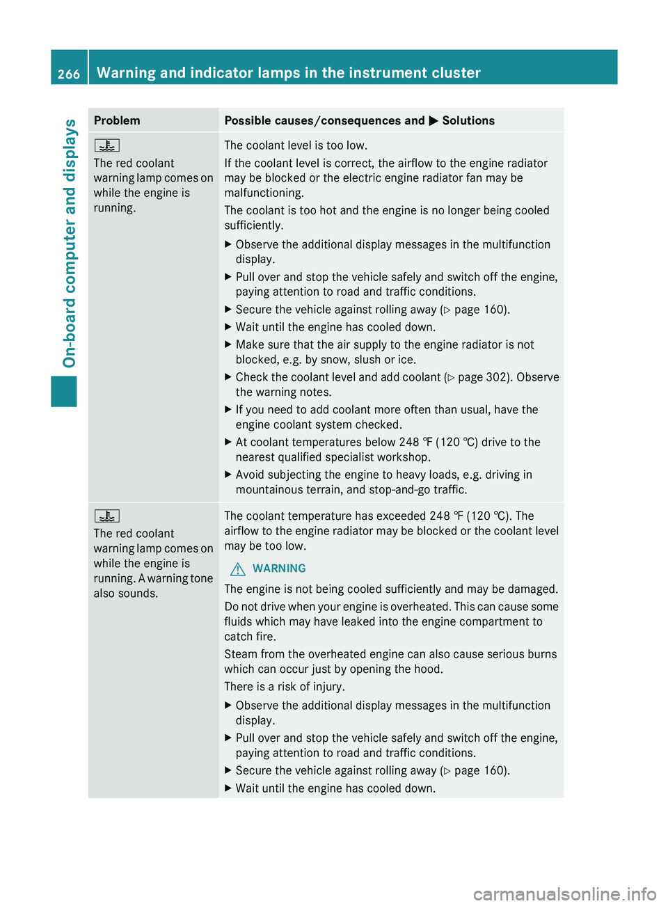
Problem Possible causes/consequences and
0050 Solutions00AC
The red coolant
warning lamp comes on
while the engine is
running.
The coolant level is too low.
If the coolant level is correct, the airflow to the engine radiator
may be blocked or the electric engine radiator fan may be
malfunctioning.
The coolant is too hot and the engine is no longer being cooled
sufficiently.
X
Observe the additional display messages in the multifunction
display.
X Pull over and stop the vehicle safely and switch off the engine,
paying attention to road and traffic conditions.
X Secure the vehicle against rolling away ( Y page 160).
X Wait until the engine has cooled down.
X Make sure that the air supply to the engine radiator is not
blocked, e.g. by snow, slush or ice.
X Check the coolant level and add coolant (Y page 302). Observe
the warning notes.
X If you need to add coolant more often than usual, have the
engine coolant system checked.
X At coolant temperatures below 248 ‡ (120 †) drive to the
nearest qualified specialist workshop.
X Avoid subjecting the engine to heavy loads, e.g. driving in
mountainous terrain, and stop-and-go traffic. 00AC
The red coolant
warning lamp comes on
while the engine is
running.
A
warning tone
also sounds. The coolant temperature has exceeded 248 ‡ (120 †). The
airflow
to the
engine radiator
may be blocked or the coolant level
may be too low.
G WARNING
The engine is not being cooled sufficiently and may be damaged.
Do not drive when your
engine is overheated. This can cause some
fluids which may have leaked into the engine compartment to
catch fire.
Steam from the overheated engine can also cause serious burns
which can occur just by opening the hood.
There is a risk of injury.
X Observe the additional display messages in the multifunction
display.
X Pull over and stop the vehicle safely and switch off the engine,
paying attention to road and traffic conditions.
X Secure the vehicle against rolling away ( Y page 160).
X Wait until the engine has cooled down.266
Warning and indicator lamps in the instrument cluster
On-board computer and displays
Page 269 of 380
Problem Possible causes/consequences and
0050 SolutionsX
Make sure that the air supply to the engine radiator is not
blocked, e.g. by snow, slush or ice.
X Check the coolant level and add coolant (Y page 302). Observe
the warning notes.
X If you need to add coolant more often than usual, have the
engine coolant system checked.
X At coolant temperatures below 248 ‡ (120 †) drive to the
nearest qualified specialist workshop.
X Avoid subjecting the engine to heavy loads, e.g. driving in
mountainous terrain, and stop-and-go traffic. Driving systems
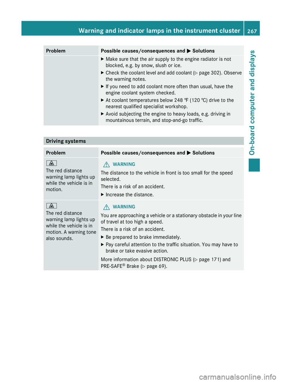
Problem Possible causes/consequences and
0050 Solutions00BA
The red distance
warning lamp lights up
while the vehicle is in
motion.
G
WARNING
The distance to the vehicle in front is too small for the speed
selected.
There is a risk of an accident.
X Increase the distance. 00BA
The red distance
warning lamp lights up
while the vehicle is in
motion. A warning tone
also sounds. G
WARNING
You are approaching a vehicle or a stationary obstacle in your line
of travel at too high a speed.
There is a risk of an accident.
X Be prepared to brake immediately.
X Pay careful attention to the traffic situation. You may have to
brake or take evasive action.
More information about DISTRONIC PLUS (Y page 171) and
PRE-SAFE ®
Brake (Y page 69). Warning and indicator lamps in the instrument cluster
267On-board computer and displays Z
Page 272 of 380
Useful information
i This Operator's Manual describes all
models and all standard and optional
equipment of your vehicle available at the
time of publication of the Operator's
Manual. Country-specific differences are
possible. Please note that your
vehicle may
not be equipped with all features
described. This also applies to safety-
related systems and functions.
i Read the information on qualified
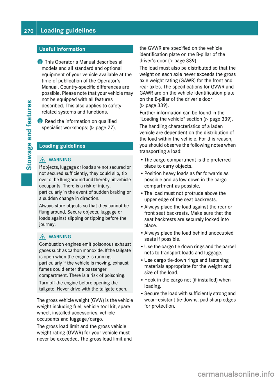
specialist workshops: ( Y page 27).Loading guidelines
G
WARNING
If objects, luggage or loads are not secured or
not secured sufficiently, they could slip, tip
over or be flung around
and thereby hit vehicle
occupants. There is a risk of injury,
particularly in the event of sudden braking or
a sudden change in direction.
Always store objects so that they cannot be
flung around. Secure objects, luggage or
loads against slipping or tipping before the
journey. G
WARNING
Combustion engines emit poisonous exhaust
gases such as carbon monoxide.
If the tailgate
is open when the engine is running,
particularly if the vehicle is moving, exhaust
fumes could enter the passenger
compartment. There is a risk of poisoning.
Turn off the engine before opening the
tailgate. Never drive with the tailgate open.
The gross vehicle weight (GVW) is the vehicle
weight including fuel, vehicle tool kit, spare
wheel, installed accessories, vehicle
occupants and luggage/cargo.
The gross load limit and the gross vehicle
weight rating (GVWR) for your vehicle must
never be exceeded. The gross load limit and the GVWR are specified on the vehicle
identification plate on the B-pillar of the
driver's door (
Y page 339).
The load must also be
distributed so that the
weight on each axle never exceeds the gross
axle weight rating (GAWR) for the front and
rear axles. The specifications for GVWR and
GAWR are on the vehicle identification plate
on the B-pillar of the driver's door
(Y page 339).
Further information can be found in the
"Loading the vehicle" section ( Y page 339).
The handling characteristics of a laden
vehicle are dependent on the distribution of
the load within the vehicle. For this reason,
you should observe the following notes when
transporting a load:
R The cargo compartment is the preferred
place to carry objects.
R Position heavy loads as far forwards as
possible and as low down in the cargo
compartment as possible.
R The load must not protrude above the
upper edge of the seat backrests.
R Always place the load against the rear or
front seat backrests. Make sure that the
seat backrests are securely locked into
place.
R Always place the load behind unoccupied
seats if possible.
R Use the cargo tie down rings and the parcel
nets to transport loads and luggage.
R Use cargo tie-down rings and fastening
materials appropriate for the weight and
size of the load.
R Hook in the cargo net (if installed) when
loading.
R Secure the load with sufficiently strong and
wear-resistant tie-downs. pad sharp edges
for protection.270
Loading guidelines
Stowage and features
Page 282 of 380
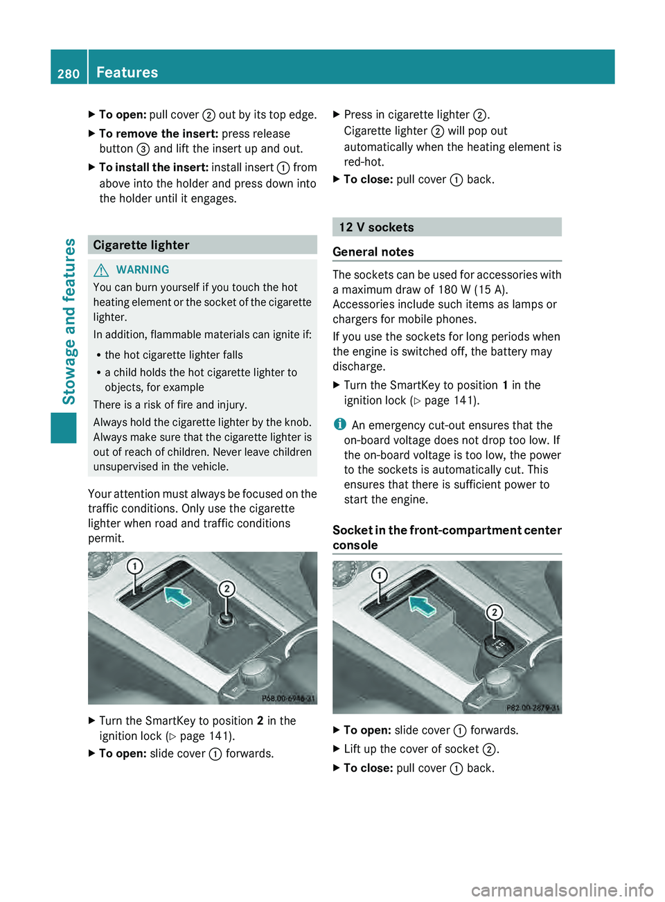
X
To open: pull cover 0044 out by its top edge.
X To remove the insert: press release
button 0087 and lift the insert up and out.
X To install the insert: install insert 0043 from
above into the holder and press down into
the holder until it engages. Cigarette lighter
G
WARNING
You can burn yourself if you touch the hot
heating element or the socket
of the cigarette
lighter.
In addition, flammable materials can ignite if:
R the hot cigarette lighter falls
R a child holds the hot cigarette lighter to
objects, for example
There is a risk of fire and injury.
Always hold the cigarette lighter by the knob.
Always make sure that the cigarette lighter is
out of reach of children. Never leave children
unsupervised in the vehicle.
Your attention must always be focused on the
traffic conditions. Only use the cigarette
lighter when road and traffic conditions
permit. X
Turn the SmartKey to position 2 in the
ignition lock (Y page 141).
X To open: slide cover 0043 forwards. X
Press in cigarette lighter 0044.
Cigarette lighter 0044 will pop out
automatically when the heating element is
red-hot.
X To close: pull cover 0043 back. 12 V sockets
General notes The sockets can be used for accessories with
a maximum draw of 180 W (15 A).
Accessories include such items as lamps or
chargers for mobile phones.
If you use the sockets for long periods when
the engine is switched off, the battery may
discharge.
X
Turn the SmartKey to position 1 in the
ignition lock ( Y
page 141).
i An emergency cut-out ensures that the
on-board voltage does not drop too low. If
the on-board voltage is too low, the power
to the sockets is automatically cut. This
ensures that there is sufficient power to
start the engine.
Socket in the front-compartment center
console X
To open: slide cover 0043 forwards.
X Lift up the cover of socket 0044.
X To close: pull cover 0043 back.280
Features
Stowage and features
Page 285 of 380

Problems with the 115 V power socket
Problem Possible causes/consequences and
0050 SolutionsThe warning lamp on
the 115 V power
socket
is not lit. The on-board voltage is too low because the battery is too weak.
X
Start the engine.
or
X Charge the battery ( Y page 316).
If the indicator lamp still does not light up:
X Visit a qualified specialist workshop. The temperature of the DC/AC converter is temporarily too high.
X
Remove the electronic device connector from the 115 V socket.
X Let the DC/AC converter cool down.
If the indicator lamp still does not light up after cooling down the
converter:
X Visit a qualified specialist workshop. You have connected a small electronic device that has a constant
nominal power of less than 150 W, but a very high switch-on
current. This device will not work. If you connect such a device,
the 115 V power socket will not supply it with power.
X
Connect a suitable device. mbrace
Important safety notes !
You must have a license agreement to
activate the mbrace service. Make sure
that your system is activated
and ready for
use. To register, press the 00D9 MB Info call
button. If any of the steps mentioned are
not carried out, the system may not be
activated.
If you have questions about the activation,
contact one of the following telephone
hotlines:
R USA: Mercedes-Benz Customer
Assistance Center at
1-800-FOR-MERCedes
(1-800-367-6372) or 1-866-990-9007
R Canada: Customer Service at
1-888-923-8367 Shortly after successfully registering with the
mbrace
service (Canada:
TELEAID), a
user ID
and password will be sent to you by post. USA
only: you can use this password to log onto
the mbrace area under "Owners Online" at
http://www.mbusa.com .
The mbrace system is available if:
R it has been activated and is operational
R the corresponding mobile phone network
is available for transmitting data to the
Customer Center
R a service subscription is available
R the starter battery is sufficiently charged
i Determining the location of the vehicle on
a map is only possible if:
R GPS reception is available.
R the vehicle position can be forwarded to
the Customer Assistance Center. Features
283
Stowage and features Z
Page 293 of 380
select the way in which you receive this
information beforehand. Possible options
include SMS, E-Mail or an automated call.
The area can be
determined
as either a circle
or a polygon with a maximum of ten corners.
You can specify up to ten areas
simultaneously. Different settings are
possible for each area.
USA only: these settings can be called up
under "Owners Online" at http://
www.mbusa.com.
Alternatively, you can trigger an MB Info call
and inform the customer service
representative that you wish to activate geo
fencing.
Currently inactive areas can be activated by
SMS.
Triggering the vehicle alarm With this function, you can trigger the
vehicle's panic alarm via SMS. An alarm
sounds and the exterior lighting flashes.
Depending on the setting, the panic alarm
lasts five or ten seconds. Afterwards, the
alarm switches off.
Garage door opener
Important safety notes G
WARNING
When you operate or program the garage door
with the integrated garage door opener,
persons in the range of movement of the
garage door can become trapped
or struck by
the garage door. There is a risk of injury.
When using the integrated garage door
opener, always make sure that nobody is
within the range of movement of the garage
door. G
WARNING
Combustion engines emit poisonous exhaust
gases such as carbon monoxide. Inhaling
these exhaust gases leads to
poisoning. There is a risk of fatal injury. Therefore never leave
the engine running in enclosed spaces
without sufficient ventilation.
The HomeLink ®
garage door opener
integrated in the rear-view mirror allows you
to operate up to three
different door and gate
systems.
Only operate garage doors using the
integrated garage door opener if:
R they are equipped with a safety stop and
reverse feature, and
R they conform to the current U.S. safety
standards.
When programming a garage door opener,
park vehicle outside the garage.
i Certain garage door drives are
incompatible with the integrated garage
door opener. If you have difficulty
programming the integrated garage door
opener, contact an authorized Mercedes-
Benz Center.
Alternatively, you can call the following
telephone assistance services:
R USA: Mercedes-Benz Customer
Assistance Center at
1-800-FOR-MERCedes
R Canada: Customer Service at
1-800-387-0100
R HomeLink ®
hotline 1-800-355-3515
(free of charge)
More information on HomeLink ®
and/or
compatible products is also available
online at http://www.homelink.com.
i Notes on the declaration of conformity
(Y page 26).
Programming Programming buttons
Observe the "Important safety notes"
(Y page 291). Features
291
Stowage and features Z
Page 299 of 380
Useful information ............................
298
ASSYST PLUS .................................... 298
Engine compartment ........................ 299
Care .................................................... 303 297Maintenance and care
Page 300 of 380

Useful information
i This Operator's Manual describes all
models and all standard and optional
equipment of your vehicle available at the
time of publication of the Operator's
Manual. Country-specific differences are
possible. Please note that your
vehicle may
not be equipped with all features
described. This also applies to safety-
related systems and functions.
i Read the information on qualified
specialist workshops: ( Y page 27).ASSYST PLUS
Service messages
The ASSYST PLUS service interval display
informs you of the next service due date.
Information on the type of
service and service
intervals (see the separate Maintenance
Booklet).
You can obtain further information from an
authorized Mercedes-Benz Center or at
http://www.mbusa.com (USA only).
i The ASSYST PLUS service interval display
does not show any information on the
engine oil level. Observe the notes on the
engine oil level ( Y page 300).
The multifunction display shows a service
message for several seconds, e.g.:
R Next Service A in .. days
R Service A Due
R Service A Exceeded by .. days
Depending on the operating conditions of the
vehicle, the remaining time or distance until
the next service due date is displayed.
The letter A or B, possibly in connection with
a number or another letter, shows the type of
service. A stands for a minor service and B for
a major service.
You can obtain further information from an
authorized Mercedes-Benz Center. The ASSYST PLUS service interval display
does not take into account any periods of
time during which the battery is
disconnected.
Maintaining the time-dependent service
schedule:
X
Note down the service due date displayed
in the multifunction display before
disconnecting the battery.
or
X After reconnecting the battery, subtract
the battery disconnection periods
from
the
service date shown on the display. Hiding a service message
X Press the 0038 or 0076 button on the
steering wheel. Displaying service messages
X Switch on the ignition.
X Press the 0059 or 0065 button on the
steering wheel to select the Serv. menu.
X Press the 0063
or 0064 button to
select the
ASSYST PLUS submenu and confirm with
0076.
The service due date appears in the
multifunction display. Information about Service
Resetting the ASSYST PLUS service
interval display !
If the ASSYST PLUS service interval
display has been inadvertently reset, this
setting can be corrected at a qualified
specialist workshop.
Have service work carried out
as described
in the Maintenance Booklet. This may
otherwise lead to increased wear and
damage to the major assemblies or the
vehicle. 298
ASSYST PLUS
Maintenance and care