2013 MERCEDES-BENZ GLA SUV key
[x] Cancel search: keyPage 233 of 401
X
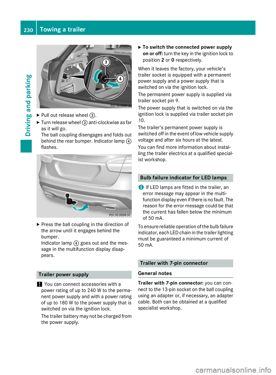
Pull out release wheel =.
X Turn release wheel =anti-clockwise as far
as it will go.
The ball coupling disengages and folds out
behind the rear bumper. Indicator lamp ?
flashes. X
Press the ball coupling in the direction of
the arrow until it engages behind the
bumper.
Indicator lamp ?goes out and the mes-
sage in the multifunction display disap-
pears. Trailer power supply
! You can connect accessories with a
power rating of up to 240 W to the perma-
nent power supply and with a power rating of up to 180 W to the power supply that is
switched on via the ignition lock.
The trailer battery may not be charged from the power supply. X
To switch the connected power supply
on or off: turn the key in the ignition lock to
position 2or 0respectively.
When it leaves the factory, your vehicle's
trailer socket is equipped with a permanent
power supply and a power supply that is
switched on via the ignition lock.
The permanent power supply is supplied via
trailer socket pin 9.
The power supply that is switched on via the
ignition lock is supplied via trailer socket pin
10.
The trailer's permanent power supply is
switched off in the event of low vehicle supply
voltage and after six hours at the latest.
You can find more information about instal-
ling the trailer electrics at a qualified special- ist workshop. Bulb failure indicator for LED lamps
i If LED lamps are fitted in the trailer, an
error message may appear in the multi-
function display even if there is no fault. The
reason for the error message could be that
the current has fallen below the minimum
of 50 mA.
To ensure reliable operation of the bulb failure indicator, each LED chain in the trailer lighting
must be guaranteed a minimum current of
50 mA. Trailer with 7-pin connector
General notes Trailer with 7-pin connector:
you can con-
nect to the 13-pin socket on the ball coupling using an adapter or, if necessary, an adapter
cable. Both can be obtained at a qualified
specialist workshop. 230
Towing a trailerDriving and parking
Page 238 of 401
At high outside temperatures and when driv-
ing uphill, the coolant temperature may rise
to the end of the scale. Rev counter
! Do not drive in the overrevving range.
Doing so will damage the engine.
The red band in the rev counter indicates the
engine's overrevving range.
The fuel supply is interrupted to protect the
engine when the red band is reached. Outside temperature display
You should pay special attention to road con-
ditions when temperatures are around the
freezing point.
The outside temperature display is in the mul- tifunction display.
Changes in the outside temperature are dis-
played after a short delay. Speedometer with segments
The speedometer is divided into segments on
vehicles with DISTRONIC PLUS.
The segments in the speedometer indicate
which speed range is available.
R Cruise control activated (Y page 188):
The segments light up from the stored
speed to the maximum speed.
R Variable SPEEDTRONIC activated
(Y page 192):
The segments light up from the start of the
scale to the selected limit speed.
R DISTRONIC PLUS activated (Y page 193):
One or two segments in the set speed
range light up.
R DISTRONIC PLUS detects a vehicle in front:
The segments between the speed of the
vehicle in front and the stored speed light
up. Operating the on-board computer
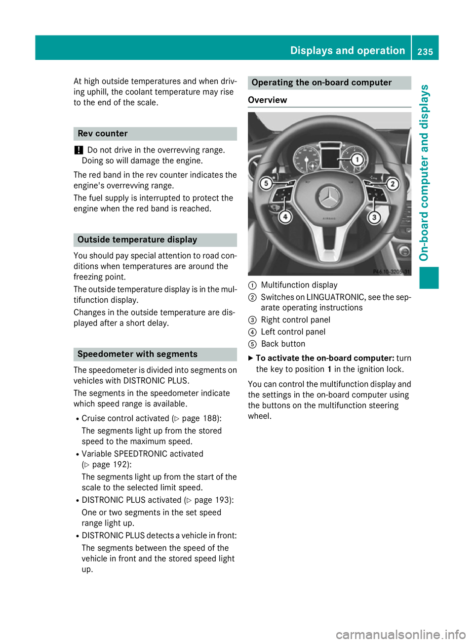
Overview :
Multifunction display
; Switches on LINGUATRONIC, see the sep-
arate operating instructions
= Right control panel
? Left control panel
A Back button
X To activate the on-board computer: turn
the key to position 1in the ignition lock.
You can control the multifunction display and
the settings in the on-board computer using
the buttons on the multifunction steering
wheel. Displays and operation
235On-board computer and displays Z
Page 251 of 401
R
surround lighting: the exterior lighting
remains lit for 40 seconds after unlocking
with the key. If you start the engine, the
surround lighting is switched off and auto-
matic headlamp mode is activated
(Y page 121).
R exterior lighting delayed switch-off: the
exterior lighting remains lit for 60 seconds
after the engine is switched off. If you close all the doors and the tailgate, the exterior
lighting goes off after 15 seconds.
X Press the =or; button on the steer-
ing wheel to select the Settings
Settings menu.
X Press the :or9 button to select the
Lights Lights submenu.
X Press ato confirm.
X Press the :or9 button to select the
Surround lighting
Surround lighting function.
When the Surround lighting
Surround lighting function is
activated, the light cone and the area
around the vehicle are displayed in orange
in the multifunction display.
X Press the abutton to save the setting.
Deactivating delayed switch-off of the exte-
rior lighting temporarily:
X Before leaving the vehicle, turn the key to
position 0in the ignition lock.
X Turn the key to position 2in the ignition
lock.
The exterior lighting delayed switch-off is
deactivated.
Delayed switch-off of the exterior lighting is
reactivated the next time you start the
engine.
i Depending on your vehicle's equipment,
when the surround lighting and delayed
switch-off exterior lighting are on, the fol-
lowing light up:
R side lamps
R foglamps
R dipped-beam headlamps
R daytime driving lights
R surround lighting in the exterior mirrors Activating/deactivating the interior light-
ing delayed switch-off
If you activate the Lighting delayed sw.-
Lighting delayed sw.-
off off function, the interior lighting remains on
for 20 seconds after you remove the key from
the ignition lock.
X Press the =or; button on the steer-
ing wheel to select the Settings
Settings menu.
X Press the :or9 button to select the
Lights
Lights submenu.
X Press ato confirm.
X Press the :or9 button to select the
Lighting delayed sw.-off
Lighting delayed sw.-off function.
If the Lighting delayed sw.-off
Lighting delayed sw.-off func-
tion has been switched on, the vehicle inte-
rior is displayed in orange in the multifunc-
tion display.
X Press the abutton to save the setting.
Vehicle Setting permanent SPEEDTRONIC
You can set permanent SPEEDTRONIC using
the
Limit Limit speed
speed(winter
(winter tyres)
tyres) function.
X Press the =or; button on the steer-
ing wheel to select the Settings
Settingsmenu.
X Press the :or9 button to select the
Vehicle
Vehicle submenu.
X Press ato confirm.
X Press :or9 to select the Limit
Limit
speed (winter tyres)
speed (winter tyres) function.
You will see the current setting.
X Press ato confirm.
X Press the :or9 button to adjust
permanent SPEEDTRONIC in increments of
ten (240 km/h 240 km/h to160 km/h
160 km/h). The Off
Offset-
ting switches permanent SPEEDTRONIC
off.
X Press the abutton to store the entry.
For further information on permanent SPEED- TRONIC (Y page 193).248
Menus and submenusOn-board computer and displays
Page 254 of 401
Resetting to factory settings
X
Press the =or; button on the steer-
ing wheel to select the Settings
Settings menu.
X Press the :or9 button to select the
Factory setting
Factory setting submenu.
X Press ato confirm.
The Reset all settings?
Reset all settings? message
appears.
X Press the :or9 button to select No
No
or Yes
Yes.
X Press the abutton to confirm the selec-
tion.
If you have selected Yes Yes, the multifunction
display shows a confirmation message.
For safety reasons, not all functions are reset: the Limit
Limit speed
speed(winter
(winter tyres)
tyres)function
in permanent SPEEDTRONIC can only be set
in the Vehicle
Vehicle submenu. If you want to reset
the Daytime
Daytime driving
drivinglights
lightsin theLights
Lights
submenu, you must turn the key to position 1
in the ignition lock. AMG menu in AMG vehicles
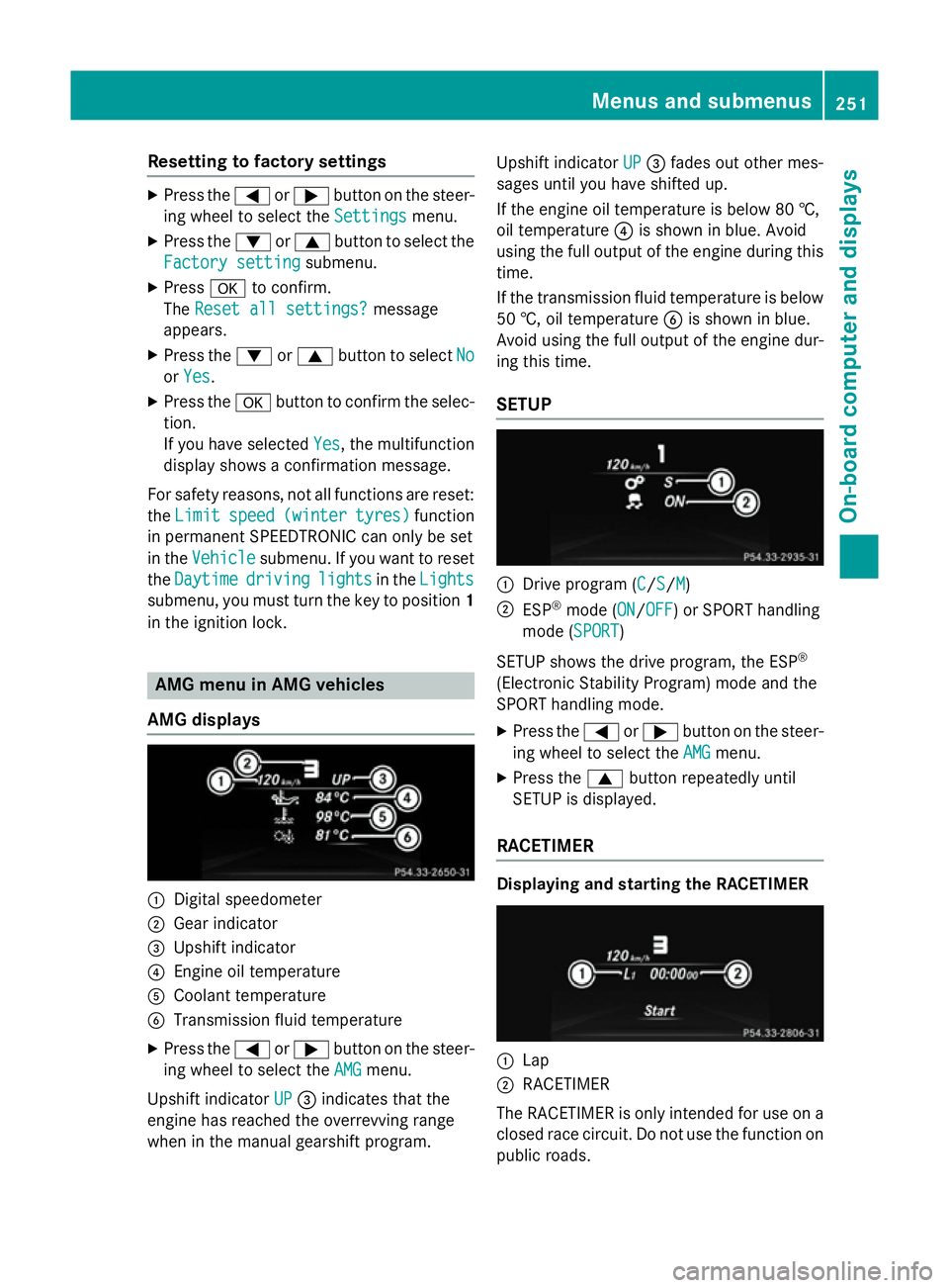
AMG displays :
Digital speedometer
; Gear indicator
= Upshift indicator
? Engine oil temperature
A Coolant temperature
B Transmission fluid temperature
X Press the =or; button on the steer-
ing wheel to select the AMG
AMG menu.
Upshift indicator UP
UP = indicates that the
engine has reached the overrevving range
when in the manual gearshift program. Upshift indicator
UP UP= fades out other mes-
sages until you have shifted up.
If the engine oil temperature is below 80 †,
oil temperature ?is shown in blue. Avoid
using the full output of the engine during this time.
If the transmission fluid temperature is below
50 †, oil temperature Bis shown in blue.
Avoid using the full output of the engine dur-
ing this time.
SETUP :
Drive program (C C/SS/MM)
; ESP ®
mode (ON ON/OFFOFF) or SPORT handling
mode (SPORT SPORT)
SETUP shows the drive program, the ESP ®
(Electronic Stability Program) mode and the
SPORT handling mode. X Press the =or; button on the steer-
ing wheel to select the AMG AMGmenu.
X Press the 9button repeatedly until
SETUP is displayed.
RACETIMER Displaying and starting the RACETIMER
:
Lap
; RACETIMER
The RACETIMER is only intended for use on a closed race circuit. Do not use the function on
public roads. Menus and submenus
251On-board computer and displays Z
Page 255 of 401
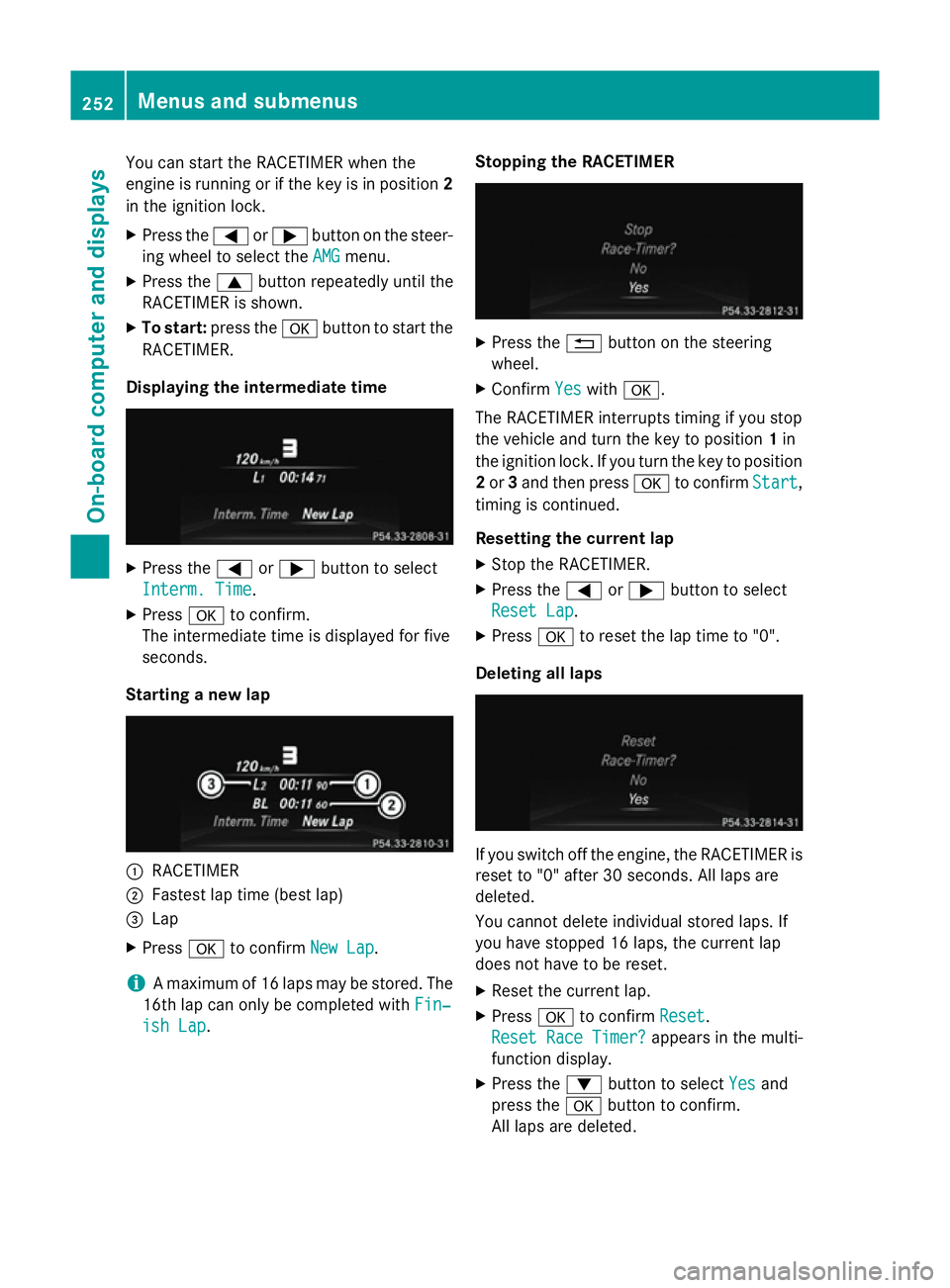
You can start the RACETIMER when the
engine is running or if the key is in position 2
in the ignition lock.
X Press the =or; button on the steer-
ing wheel to select the AMG
AMGmenu.
X Press the 9button repeatedly until the
RACETIMER is shown.
X To start: press the abutton to start the
RACETIMER.
Displaying the intermediate time X
Press the =or; button to select
Interm. Time
Interm. Time .
X Press ato confirm.
The intermediate time is displayed for five
seconds.
Starting a new lap :
RACETIMER
; Fastest lap time (best lap)
= Lap
X Press ato confirm New Lap New Lap.
i A maximum of 16 laps may be stored. The
16th lap can only be completed with Fin‐
Fin‐
ish Lap
ish Lap. Stopping the RACETIMER X
Press the %button on the steering
wheel.
X Confirm Yes
Yeswith a.
The RACETIMER interrupts timing if you stop
the vehicle and turn the key to position 1in
the ignition lock. If you turn the key to position
2 or 3and then press ato confirm Start Start,
timing is continued.
Resetting the current lap
X Stop the RACETIMER.
X Press the =or; button to select
Reset Lap Reset Lap.
X Press ato reset the lap time to "0".
Deleting all laps If you switch off the engine, the RACETIMER is
reset to "0" after 30 seconds. All laps are
deleted.
You cannot delete individual stored laps. If
you have stopped 16 laps, the current lap
does not have to be reset.
X Reset the current lap.
X Press ato confirm Reset
Reset.
Reset Race Timer? Reset Race Timer? appears in the multi-
function display.
X Press the :button to select Yes
Yes and
press the abutton to confirm.
All laps are deleted. 252
Menus and submenusOn-board computer and displays
Page 263 of 401

Display messages
Possible causes/consequences and
M
MSolutions The yellow
!warning lamp lights up. If you manually apply or
release the electric parking brake, the red !indicator lamp
flashes.
The electric parking brake is malfunctioning. It is not possible to
apply the electric parking brake manually.
X Vehicles with manual transmission: engage first gear.
X Vehicles with automatic transmission: shift the transmission
to P.
X Visit a qualified specialist workshop. !
Parking Parking
brake
brakeinop‐
inop‐
erative
erative The yellow
!warning lamp lights up. The red !indicator
lamp flashes for about ten seconds after the electric parking brake
has been applied or released. It then goes out or remains lit.
The electric parking brake is malfunctioning, e.g. because of over- voltage or undervoltage.
X Rectify the cause of the overvoltage or undervoltage, e.g. by
charging the battery or restarting the engine.
X Apply or release the electric parking brake.
If the electric parking brake still cannot be applied or released: X Switch off the ignition and turn it back on.
X Apply or release the electric parking brake.
If the electric parking brake still cannot be released: X Consult a qualified specialist workshop. The red
!indicator lamp flashes and the yellow !warning
lamp is lit.
It is not possible to apply the electric parking brake manually.
X Vehicles with manual transmission: engage first gear.
X Vehicles with automatic transmission: shift the transmission
to P.
X Visit a qualified specialist workshop. !
Turn on the igni‐ Turn on the igni‐
tion to release tion to release
the parking brake the parking brake The red
!indicator lamp lights up.
You attempted to release the electric parking brake while the igni-
tion was switched off.
X Turn the key to position 1in the ignition lock. 260
Display
messagesOn-board computer and displays
Page 290 of 401

Display messages
Possible causes/consequences and
M
MSolutions Telephone No ser‐
Telephone No ser‐
vice vice Your vehicle is outside the network provider's transmitter/
receiver range.
X Wait until the mobile phone operational readiness symbol
appears in the multifunction display. ¥
Top Top
up
upwasher
washer fluid
fluid The washer fluid level in the washer fluid reservoir has dropped
below the minimum.
i If, during the winter months, you do not add antifreeze to the
washer fluid, it may freeze in the washer fluid container. In this
case, the Top Topup
upwasher
washer fluid
fluiddisplay message may appear
in the multifunction display.
X Top up the washer fluid (Y page 321).Wiper malfunction‐
Wiper malfunction‐
ing ing The windscreen wipers are defective.
X Visit a qualified specialist workshop. Hazard warning
Hazard warning
lamps malfunction‐ lamps malfunction‐
ing ing The hazard warning lamps are faulty.
X Visit a qualified specialist workshop. Key
Display messages
Possible causes/consequences and
M
MSolutions +
Key does not Key does not
belong to vehicle belong to vehicle You have put the wrong key in the ignition lock.
X Use the correct key. +
Replace key Replace key The key needs to be replaced.
X Visit a qualified specialist workshop. Display
messages
287On-board computer and displays Z
Page 314 of 401
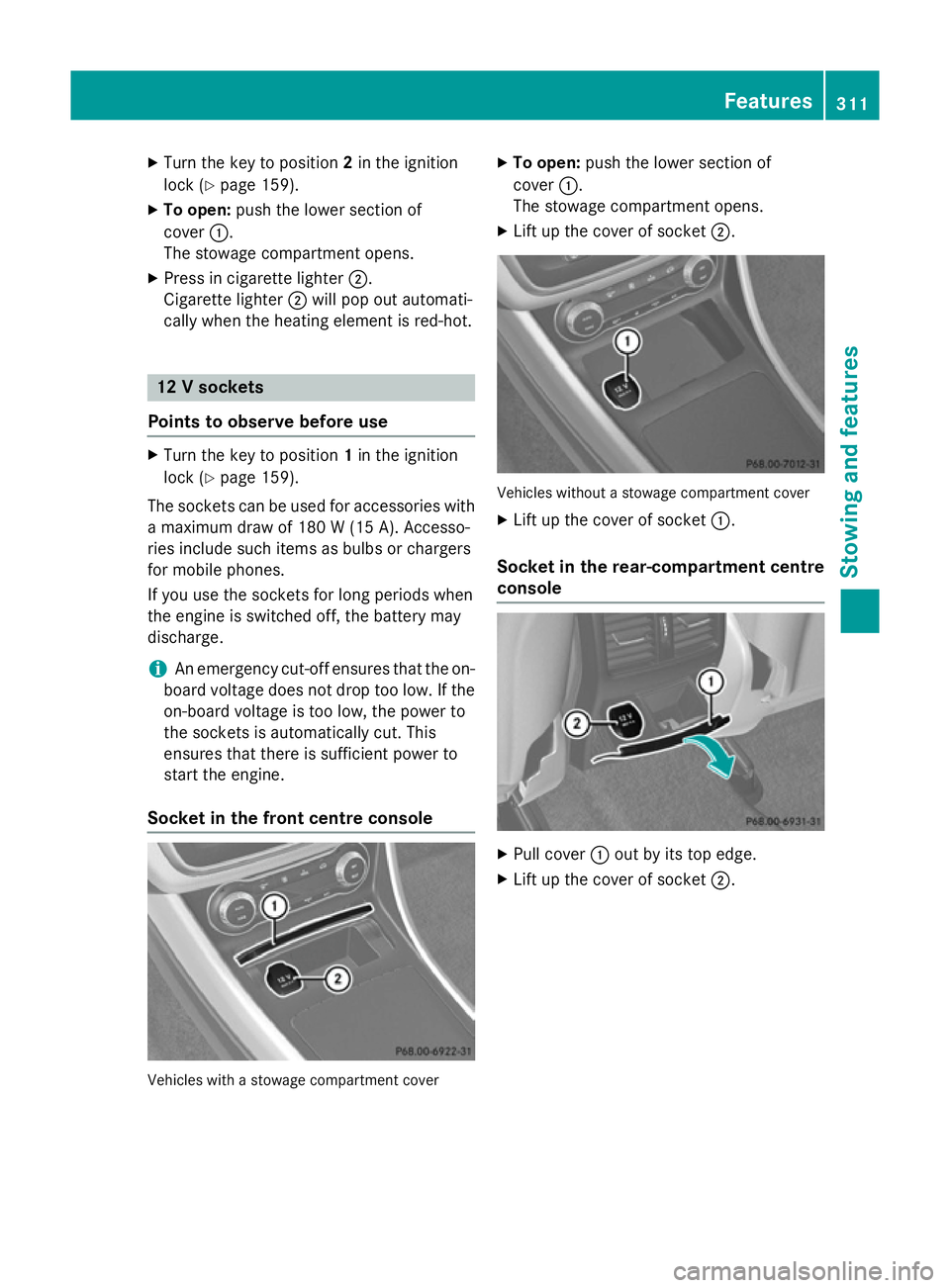
X
Turn the key to position 2in the ignition
lock (Y page 159).
X To open: push the lower section of
cover :.
The stowage compartment opens.
X Press in cigarette lighter ;.
Cigarette lighter ;will pop out automati-
cally when the heating element is red-hot. 12 V sockets
Points to observe before use X
Turn the key to position 1in the ignition
lock (Y page 159).
The sockets can be used for accessories with a maximum draw of 180 W (15 A). Accesso-
ries include such items as bulbs or chargers
for mobile phones.
If you use the sockets for long periods when
the engine is switched off, the battery may
discharge.
i An emergency cut-off ensures that the on-
board voltage does not drop too low. If the on-board voltage is too low, the power to
the sockets is automatically cut. This
ensures that there is sufficient power to
start the engine.
Socket in the front centre console Vehicles with a stowage compartment cover X
To open: push the lower section of
cover :.
The stowage compartment opens.
X Lift up the cover of socket ;. Vehicles without a stowage compartment cover
X Lift up the cover of socket :.
Socket in the rear-compartment centre
console X
Pull cover :out by its top edge.
X Lift up the cover of socket ;. Features
311Stowing and features Z