2013 MERCEDES-BENZ GL towing
[x] Cancel search: towingPage 262 of 454

Ball coupling recess
Holes in the ball coupling and ball coupling recess
X
Insert the ball coupling horizontally into ball
coupling recess 0003in the direction of the
arrow until the holes in ball coupling 0021are
in line with the holes in ball coupling
recess 0020. Bolt
X
Slide bolt 001Einto the hole in the ball
coupling recess and the ball coupling to the
stop. Bolt and spring cotter
X
Secure the bol tusing spring cotter 001F. Correctly installed and secured ball coupling
X
Check the ball coupling, bolt and spring
cotter for correct installation.
If the ball coupling cannot be correctly
mounted, remove the ball coupling. Under
these circumstances, the ball coupling must
not be used for trailer towing.
If the ball coupling cannot be locked and the
key cannot be removed, remove the ball
coupling and clean it. If the ball coupling can
still not be installed (locked) after it has been
cleaned, remove the ball coupling. The trailer
tow hitch must then not be used to tow a
trailer, as safe operation cannot be
guaranteed.
Have the entire trailer tow hitch checked at a
qualified specialist workshop. Coupling up a trailer
! Do not connect the trailer's brake system
(if featured) to the hydraulic brake system 260
Towing
atrailerDriving an d parking
Page 263 of 454

of the towing vehicle, as the latter is
equipped with an anti-lock brake system.
Doing so will result in a loss of function of
the brake systems of both the vehicle and
the trailer.
X Make sure that the automatic transmission
is set to position P.
X Apply the vehicle's electric parking brake.
X Start the engine.
X Vehicles with the AIRMATIC package:
select highway level.
X Vehicles with ADS: set ADS toAUTOor
COMF.
X Switch off the engine.
X Close all doors and the tailgate.
X Couple up the trailer.
X Establish all electrical connections.
X Check that the trailer lighting system is
working.
i Vehicles with the AIRMATIC package:
with a trailer attached, the vehicle will
always remain at highway level. When
coupling up a trailer, please observe the
following:
R Unless highway level has been set
manually, the vehicle is automatically
lowered to highway level. This is the case
if a speed of 5mph(8km/h) is reached.
R High-speed level is not available.
These restrictions apply to all accessories
powered through a connectio nto the trailer
power socket of your vehicle, e.g. a bicycle
carrier.
Observe the maximum permissible trailer
dimensions (width and length).
Most U.S. states and all Canadia nprovinces
require by law:
R Safety chains between the towing vehicle
and the trailer. The chains should be cross-
wound under the trailer drawbar. They must
be fastened to the vehicle's trailer
coupling, not to the bumper or the axle. Leave enough play in the chains to make
tight cornering possible.
R As eparate brake system for certain types
of trailer.
R As afety switch for braked trailers. Check
the specific legal requirements applicable
to your state.
If the trailer detaches from the towing
vehicle, the safety switch applies the
trailer's brakes. Towing
atrailer
There are numerous legal requirements
concerning the towing of a trailer, e.g .speed
restrictions. Make sure that your vehicle/
trailer combination complies with the local
requirements not only in your area of
residence but also at any location to which
you are traveling. The police and local
authorities can provide reliable information.
Please observe the following when towing a
trailer:
R To acquaint yourself with driving with a
trailer and with the resulting changes to
handling, you should practice cornering,
stopping and backing up in a traffic-free
location.
R Before driving, check:
-Trailer tow hitch
- Safety switch for braked trailers
- Safety chains
- Electrical connections
- Lights
- the wheels
R Adjust the exterior mirrors to provide an
unobstructed view of the rear section of the
trailer.
R If the trailer features electronically
controlled brakes, pull away the vehicle/
trailer combination carefully, manually
brake using the brake controller, and check
the brakes for correct function. Towing
atrailer
261Driving an d parking Z
Page 264 of 454

R
Secure any objects on the traile rto prevent
the cargo from slipping when the vehicle is
in motion.
R If you couple up a trailer, regularly check
the cargo for secure fastening and make
sure that the trailer lamps and (if
applicable) the trailer brakes are
functioning correctly.
R Bear in mind that the handling will be less
stable when towing a trailer than when
driving without one. Avoid sudden steering
movements.
R The vehicle/trailer combination is heavier,
accelerates more slowly, has a decreased
gradient climbing capability and a longer
braking distance.
It is more susceptible to side winds and
requires more careful steering.
R If possible, avoid abrupt braking. Depress
the brake pedal moderately at first, so that
the trailer can activate its own brakes. Then
increase the pressure on the brake pedal.
R If the automatic transmission continues to
shift back and forth between two gears
when driving up or downhill, restrict the
shift range. Select shift range 4, 3, 2,or1.
Al ower gear and lower speed reduce the
risk of engine failure.
R When driving downhill, shift to a lower gear
to utilize the engine's braking effect.
Avoid continuous brake application as this
may overheat the vehicle brakes and, if
installed, the trailer brakes.
R If the coolant temperature increases
dramatically while the air-conditioning
system is switched on, switch off the air-
conditioning system.
Coolant heat can additionally be dissipated
by opening the windows and by setting the
blower fan and the interior temperature to
maximum.
R When overtaking, pay particular attention
to the extended length of your vehicle/
trailer combination. Due to the length of your vehicle/trailer
combination, you will have to travel an
additional distance beyond the vehicle you
are overtaking before returning to the
previous lane. Decoupling
atrailer G
WARNING
If you uncouple a trailer with the overrun
brake engaged, you could trap your hand
between the vehicle and the trailer drawbar.
There is a risk of injury.
Do not uncouple a trailer if the overru nbrake
is engaged. G
WARNING
Vehicles with level control:
The vehicle is lowered as soon as you
disconnect the trailer cable. This could result
in yourl imbs or those of other people that are
betwee nthe vehicle body and tires or
underneath the vehicle being trapped. There
is a risk of injury.
Make sure that nobody is in the immediate
vicinity of the wheel housings or under the
vehicle when you disconnectt he trailer cable.
! Do not disconnect a trailer with an
engaged overrun brake. Otherwise, your
vehicle could be damaged by the
rebounding of the overrun brake.
X Make sure that the automatic transmission
is set to position P.
X Apply the vehicle's electric parking brake.
X Start the engine.
X Close all doors and the tailgate.
X Apply the trailer's parking brake.
X Detach the trailer cable and decouple the
trailer.
X Switch off the engine. 262
Towing
atrailerDriving an d parking
Page 265 of 454

Permissible trailer loads and drawbar
loads
Weight specifications Maximump
ermissible gross vehicle
weight rating
The gross trailer weight is calculated by
adding the weight of the trailer to the weight
of the load and equipment on the trailer.
Permissible gross weight :7,500 lb
(3,402 kg).
Permissible noseweight
The maximum permissible trailer drawbar
noseweight is the maximum weight with
which the trailer drawbar can be loaded:
600 lbs (272 kg).
Limit for Mercedes-Benz-approved trailer
couplings.
Loading atrailer R
When loading the trailer, make sure that
neithe rthe permissible gross weight of the
trailer nor the gross vehicle weight is
exceeded. The permissible gross vehicle
weight is indicated on the identification
plate on the B-pillar on the driver's side of
the vehicle.
You can find the maximum permissible
values on the type plates of your vehicle
and the trailer. When calculating how much
weight the vehicle and trailer may carry,
pay attention to the respective lowest
values.
R The trailer drawbarl oad on the ball coupling
must be added to the rear axle load to avoid
exceeding the permissible gross axle
weight. The permissible gross vehicle
weight is indicated on the identification
plate on the B-pillar on the driver's side of
the vehicle.
i Mercedes-Benz recommends atrailer
load where the trailer drawbar noseweight
accounts for 8% to 15% of the trailer's
permissible gross weight. i
The weight of additional accessories,
passengers, and cargo reduces the
permissible trailer load and drawbar load
for yourv ehicle.
Checking the vehicle and trailer weight R
To chec kthat the weights of the towing
vehicle and the trailer comply with the
maximum permissible values, have the
vehicle/trailer combination (including the
driver, passengers, and cargo with a fully
laden trailer) weighed on a calibrated
weighbridge.
R Check the gross axle weight rating of the
front and rear axles, the gross weight of the
trailer and trailer drawbarl oad. Removing the ball coupling
X Remove the spring cotter.
X Remove the bolt from the ball coupling
recess.
X Remove the ball coupling from the ball
coupling recess.
X Clean the ball coupling if it is dirty.
Information on cleaning and care of the trailer
tow hitch can be found at (Y page 376). Storing the ball coupling
G
WARNING
Do not carry the ball coupling in the vehicle
interior if it is not secured.
Otherwise, you and others could be injured by
the ball coupling being thrown around if you:
R brake sharply
R change direction suddenly
R are involved in an accident Towing
atrailer
263Driving an d parking Z
Page 266 of 454

Trailer power supply
! You can connect accessorie swith a
maximum power consumption of 240 Wto
the permanent powe rsupply.
You must no tcharge a trailer battery using
the power supply.
The trailer socket of your vehicle is equipped
at the factory with apermanen tpower supply.
The permanent power supply is supplied via
trailer socket pin 4.
The trailer's permanent power supply is
switched off in the event of low vehicle supply
voltage and after six hours at the latest.
Aq ualified specialist workshop can provide
more information about installing the trailer
electrics. 264
Towing
atrailerDriving an d parking
Page 308 of 454

Display messages Possible causes/consequences and
0001 Solutions
0002
Check
Additive See
Operator's Manual The DEF tank is almost empty.
X
Have the DE Ftank filled as soon as possible at aqualified
specialist workshop (Y page 181).0002
Remaining Starts:
16 The DE
Flevel has fallen to a minimum. You can start the engine a
further 16 times.
X Have the DEFt ank filled immediately at a qualified specialist
workshop (Y page 181).
i You can start the engine a further 16 times. If DE Fis not added,
it will then not be possible to restart the engine. Refill the DEF
tank with approximately 1 gal (3.8 l) DEF (Y page 181).Driving systems
Display messages Possible causes/consequences and
0001 Solutions
0003
Attention Assist:
Take a Break! Based on certain criteria, ATTENTION ASSIST has detected fatigue
or
alack of concentration on th epart of th edriver. A warning tone
also sounds.
X If necessary, take a break.
During long journeys, take regular breaks in good time so you get
enough rest. 0003
Attention Assist
Inoperative ATTENTION ASSIST is inoperative.
X
Visi taqualified specialist workshop. 0002
Drive More Slowly You cannot change the vehicle level. Possible causes are:
R
you are driving too fast for the selected vehicle level.
R you are towing a trailer.
R the trailer-coupling socket is being used, e.g. for a bicycle rack.
X Drive more slowly and then select the desired vehicle level
again.
R
Vehicles with the ON&OFFROA Dpackage (Y page 207)
R Vehicles with the AIRMATIC package (Y page 213)
X Observe the notes on towing a trailer (Y page 257).306
Display messagesOn-board computer and displays
Page 312 of 454
Display messages Possible causes/consequences and
0001 Solutions
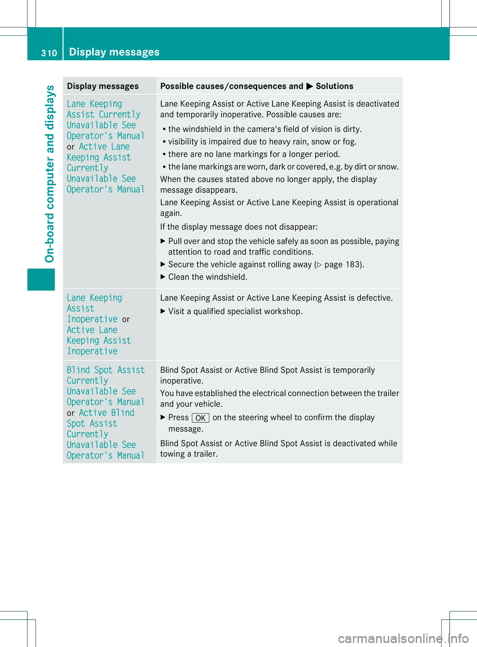
Lane Keeping
Assist Currently
Unavailable See
Operator's Manual
or
Active Lane Keeping Assist
Currently
Unavailable See
Operator's Manual Lane Keeping Assis
torActive Lane Keeping Assist is deactivated
and temporarily inoperative .Possible causes are:
R the windshield in the camera's field of vision is dirty.
R visibility is impaired due to heavy rain, snow or fog.
R there are no lane markings for a longer period.
R the lane markings are worn, dark or covered, e.g. by dirt or snow.
When the causes stated above no longer apply, the display
message disappears.
Lane Keeping Assist or Active Lane Keeping Assist is operational
again.
If the display message does not disappear:
X Pull over and stop the vehicle safely as soon as possible, paying
attention to road and traffic conditions.
X Secure the vehicle against rolling away (Y page 183).
X Clean the windshield. Lane Keeping
Assist
Inoperative or
Active Lane Keeping Assist
Inoperative Lane Keeping Assist or Active Lane Keeping Assist is defective.
X
Visit a qualified specialist workshop. Blind Spot Assist
Currently
Unavailable See
Operator's Manual
or
Active Blind Spot Assist
Currently
Unavailable See
Operator's Manual Blind Spot Assist or Active Blind Spot Assist is temporarily
inoperative.
You have established the electrical connection between the trailer
and your vehicle.
X
Press 000Bon the steering wheel to confirm the display
message.
Blind Spot Assist or Active Blind Spot Assist is deactivated while
towing a trailer. 310
Display messagesOn-board computer and displays
Page 339 of 454

Stowage space
Important safety notes G
WARNING
If objects in the passenger compartment are
stowed incorrectly, they can slide or be
thrown around and hit vehicle occupants.
There is a risk of injury, particularly in the
event of sudden braking or a sudden change
in direction.
R Always stow objects so that they cannot be
thrown around in such situations.
R Always make sure that objects do not
protrude from stowage spaces, parcel nets
or stowage nets.
R Close the lockable stowage spaces while
driving.
R Stow and secure objects that are heavy,
hard, pointy, sharp-edged, fragile or too
large in the cargo compartment.
Observe the loading guidelines (Y page 336).
Glove box X
To open: pull handle 0002and open glove box
flap 0003.
X To close: fold glove box flap 0003upwards
until it engages.
i The glove box can be cooled and
ventilated (Y page 159). 0004
Glove box unlocked
0005 Glove box locked
The glove box can be locked and unlocked
using the mechanical key. Partition
0002for stowing flat objects is located
in the upper section of the glove box. It can
be removed to increase the stowage space in
the glove box.
X To remove: pull partition 0002forwards and
out
X To install: insert partition 0002and push it
back until it engages. Stowage areas
337Stowage and features Z