Page 329 of 352

Rthe jack must be placed on a firm, flat and
non-slip surface. On a loose surface, a
large, load-bearing underlay must be used.
On a slippery surface, a non-slip underlay
must be used, e.g. rubber mats.
R do not use wooden blocks or similar
objects as a jack underlay. Otherwise, the
jack will not be able to achieve its load-
bearing capacity due to the restricted
height.
R make sure that the distance between the
underside of the tyres and the ground does
not exceed 3 cm.
R never place your hands or feet under the
raised vehicle.
R never lie under the raised vehicle.
R never start the engine when the vehicle is
raised.
R never open or close a door or the boot lid
when the vehicle is raised.
R make sure that no persons are present in
the vehicle when the vehicle is raised.
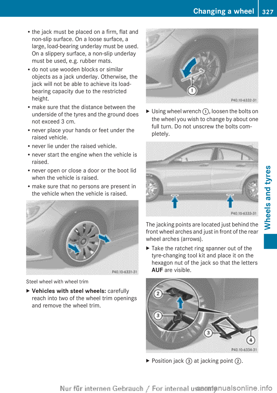
Steel wheel with wheel trim
XVehicles with steel wheels: carefully
reach into two of the wheel trim openings
and remove the wheel trim.XUsing wheel wrench :, loosen the bolts on
the wheel you wish to change by about one
full turn. Do not unscrew the bolts com-
pletely.
The jacking points are located just behind the
front wheel arches and just in front of the rear
wheel arches (arrows).
XTake the ratchet ring spanner out of the
tyre-changing tool kit and place it on the
hexagon nut of the jack so that the letters
AUF are visible.XPosition jack = at jacking point ;.Changing a wheel327Wheels and tyresZ
Page 334 of 352

When using an emergency spare wheel or
spare wheel of a different size, you must not
exceed the maximum speed of 80 km/h.
Snow chains must not be fitted to emergency
spare wheels.
General notes
i Apart from some country-specific var-
iants, the vehicles are not equipped with an
emergency spare wheel. Emergency spare
wheels are specific to the vehicle. For more
information on which emergency spare
wheels are approved for your vehicle, con-
sult a qualified specialist workshop.
You should regularly check the pressure of all
your tyres, including the emergency spare
wheel, particularly prior to long trips, and cor-
rect the pressure as necessary (Y page 319).
The value on the wheel or as given in the
"Wheels and tyres" section ( Y page 332) is
valid.
i If you are driving with the collapsible
emergency spare wheel fitted, the tyre
pressure loss warning system or the tyre
pressure monitor cannot function reliably.
Only restart the tyre pressure loss warning
system/tyre pressure monitor when the
defective wheel has been replaced with a
new wheel.
Vehicles with tyre pressure monitor:
after mounting an emergency spare wheel,
the system may still display the tyre pres-
sure of the removed wheel for a few
minutes. The value displayed for the moun-
ted emergency spare wheel is not the same
as the current tyre pressure of the emer-
gency spare wheel.
An emergency spare wheel may also be fitted
against the direction of rotation. Observe the
time restriction on use as well as the speed
limitation specified on the emergency spare
wheel.
Replace the tyres after six years at the latest,
regardless of wear. This also applies to the
emergency spare wheel.
Removing the emergency spare wheel
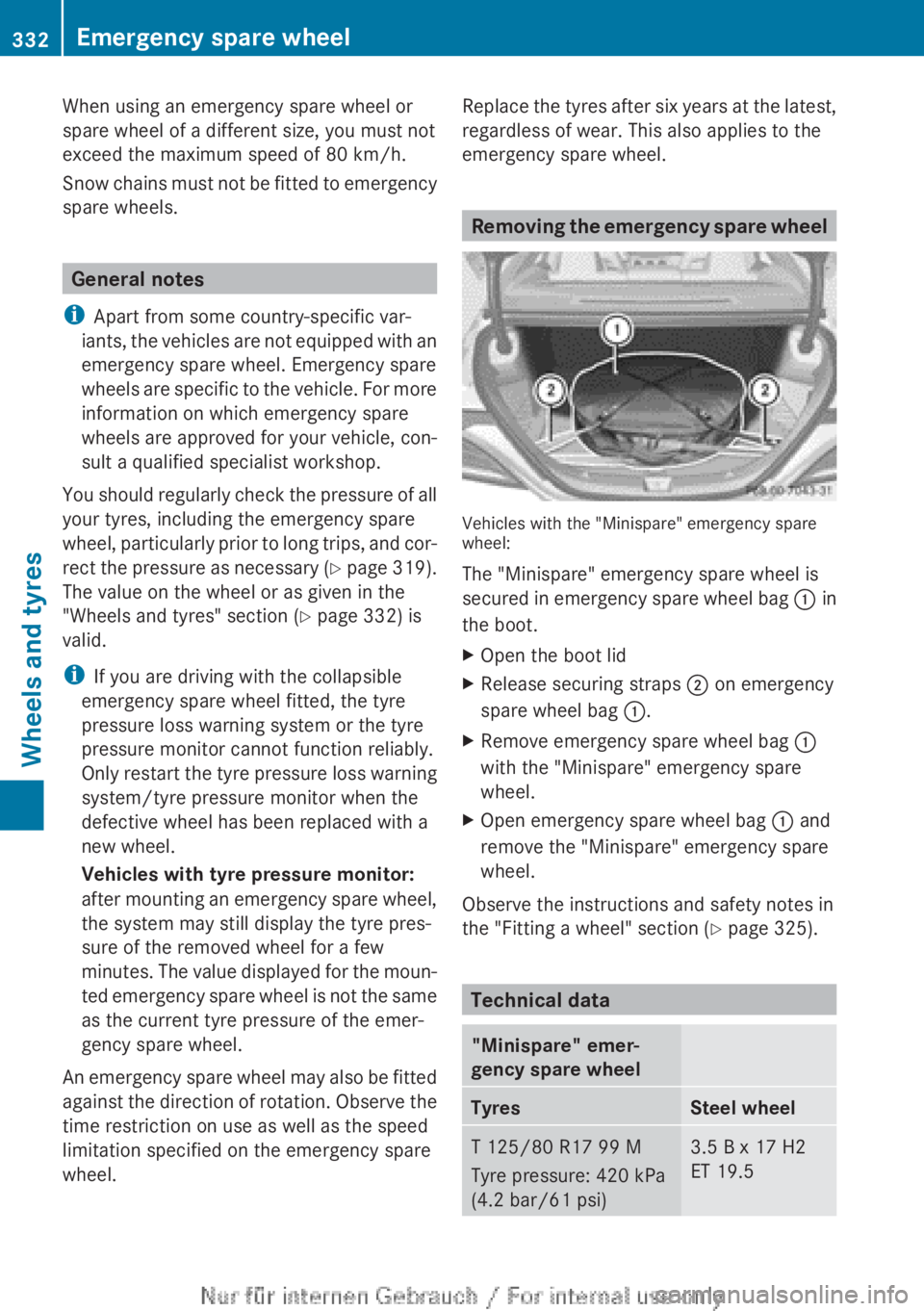
Vehicles with the "Minispare" emergency spare
wheel:
The "Minispare" emergency spare wheel is
secured in emergency spare wheel bag : in
the boot.
XOpen the boot lidXRelease securing straps ; on emergency
spare wheel bag :.XRemove emergency spare wheel bag :
with the "Minispare" emergency spare
wheel.XOpen emergency spare wheel bag : and
remove the "Minispare" emergency spare
wheel.
Observe the instructions and safety notes in
the "Fitting a wheel" section ( Y page 325).
Technical data
"Minispare" emer-
gency spare wheelTyresSteel wheelT 125/80 R17 99 M
Tyre pressure: 420 kPa
(4.2 bar/61 psi)3.5 B x 17 H2
ET 19.5332Emergency spare wheelWheels and tyres
Page 337 of 352

sion surrounding the possible health risk
posed by electromagnetic fields.
Observe the notes on operating mobile
phones ( Y page 278).
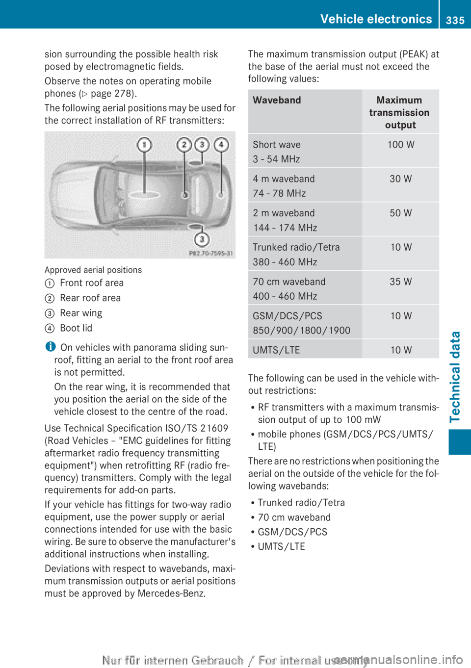
The following aerial positions may be used for
the correct installation of RF transmitters:
Approved aerial positions
:Front roof area;Rear roof area=Rear wing?Boot lid
i On vehicles with panorama sliding sun-
roof, fitting an aerial to the front roof area
is not permitted.
On the rear wing, it is recommended that
you position the aerial on the side of the
vehicle closest to the centre of the road.
Use Technical Specification ISO/TS 21609
(Road Vehicles – "EMC guidelines for fitting
aftermarket radio frequency transmitting
equipment") when retrofitting RF (radio fre-
quency) transmitters. Comply with the legal
requirements for add-on parts.
If your vehicle has fittings for two-way radio
equipment, use the power supply or aerial
connections intended for use with the basic
wiring. Be sure to observe the manufacturer's
additional instructions when installing.
Deviations with respect to wavebands, maxi-
mum transmission outputs or aerial positions
must be approved by Mercedes-Benz.
The maximum transmission output (PEAK) at
the base of the aerial must not exceed the
following values:WavebandMaximum
transmission outputShort wave
3 - 54 MHz100 W4 m waveband
74 - 78 MHz30 W2 m waveband
144 - 174 MHz50 WTrunked radio/Tetra
380 - 460 MHz10 W70 cm waveband
400 - 460 MHz35 WGSM/DCS/PCS
850/900/1800/190010 WUMTS/LTE10 W
The following can be used in the vehicle with-
out restrictions:
R RF transmitters with a maximum transmis-
sion output of up to 100 mW
R mobile phones (GSM/DCS/PCS/UMTS/
LTE)
There are no restrictions when positioning the
aerial on the outside of the vehicle for the fol-
lowing wavebands:
R Trunked radio/Tetra
R 70 cm waveband
R GSM/DCS/PCS
R UMTS/LTE
Vehicle electronics335Technical dataZ
Page 345 of 352

At temperatures below freezing:XFill the washer fluid reservoir with a mixture
of water and washer fluid, e.g. MB Winter-
Fit.
Adapt the mixing ratio to the outside temper-
ature.
R Down to Ò10 † : mix 1 part MB WinterFit to
2 parts water.
R Down to Ò20 † : mix 1 part MB WinterFit to
1 part water.
R Down to Ò29 †: mix 2 parts MB WinterFit
to 1 part water.
i Add washer fluid concentrate, e.g. MB
SummerFit or MB WinterFit, to the washer
fluid all year round.
Vehicle data
General notes
Please note that for the specified vehicle
data:
R the heights specified may vary as a result
of:
- tyres
- load
- condition of the suspension
- optional equipment
R items of optional equipment increase the
unladen weight and reduce the maximum
payload. The unladen weight is specified in
accordance with EC directives and
includes:
- driver (68 kg)
- luggage (7 kg)
- all fluids (fuel tank 90% full)
R vehicle-specific weight information can be
found on the vehicle identification plate
( Y page 336).
R only for certain countries: you can find vehi-
cle-specific vehicle data in the COC docu-
ments (CERTIFICATE OF CONFORMITY).
These documents are delivered with your
vehicle.
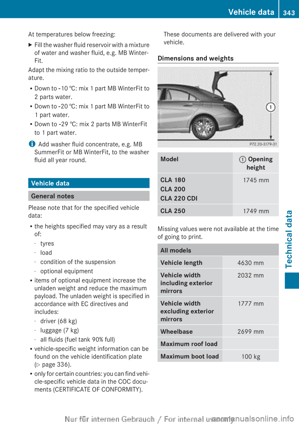
Dimensions and weightsModel: Opening
heightCLA 180
CLA 200
CLA 220 CDI1745 mmCLA 2501749 mm
Missing values were not available at the time
of going to print.
All modelsVehicle length4630 mmVehicle width
including exterior
mirrors2032 mmVehicle width
excluding exterior
mirrors1777 mmWheelbase2699 mmMaximum roof loadMaximum boot load100 kgVehicle data343Technical dataZ